Sign In
Upload
Manuals
Brands
JUKI Manuals
Sewing Machine
AMS-210EN Series
JUKI AMS-210EN Series Manuals
Manuals and User Guides for JUKI AMS-210EN Series. We have
3
JUKI AMS-210EN Series manuals available for free PDF download: Engineer's Manual, Instruction Manual, Quick Start Manual
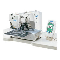
JUKI AMS-210EN Series Engineer's Manual (249 pages)
Computer-controlled, Cycle Machine With Input Function
Brand:
JUKI
| Category:
Sewing Machine
| Size: 5.62 MB
Table of Contents
Table of Contents
3
Specifications
8
Configuration
9
Names of Main Unit
9
Operation Panel
10
Standard Adjustment
12
Main Shaft Connection/Disconnection
12
Removal of Main Shaft Motor and Coupling
14
Crank Rod Connection/Disconnection
16
Crank Balancer Positioning
18
Adjustment of Intermediate Presser Cam
20
Adjustment of Intermediate Presser Bar
20
Intermediate Presser Variable Connection/Disconnection
22
Intermediate Presser Variable Adjustments
24
Intermediate Presser Drivie Arm
26
Lower Shaft Backlash Adjustment and Connection/Disconnection
28
Oscillator Gear Positioning
28
Adjustment of Hook Oil Amount
30
Shuttle Connection / Disconnection and Oil Wick Piping
30
Adjusting the Height of the Needle Bar
32
Hook Adjustment
34
Thread Trimmer Presser Lifter Cam Connection/Disconnection
36
Thread Trimmer and Presser Origin Sensor Adjustment
36
Adjustment of the Moving Knife and Counter Knife Position
38
Floating Amount of the Thread Tension Disk
38
Second Thread Tension Connection / Disconnection
40
AT Unit Connection / Disconnection
42
Wiper Adjustment
44
Adjusting the Pre-Load of the X-Y Table
46
Adjustment of the Tension of the X Timing Belt
48
Adjustment to Positions of X-Motor and Y-Motor (Backlash Adjustment to Gear)
50
Adjusting of the Presser Lower Arm (Motor Type Only)
50
Adjustment When the Presser Plate Sheet Is Replaced (Motor Type Only)
52
Height of the Slider and Pasting of the Presser Plate Sheet (Pneumatic Type Only)
54
Adjusting the Speed of the Work Clamp Feet (Pneumatic Type Only)
56
Making the Origin Setting Gauge
58
Adjusting the X Origin Sensor
58
Adjusting the y Origin Sensor
60
Adjustment of the Bobbin Winder Driving Wheel Position
62
Adjusting the Bobbin Winder Amount
62
Adjustment of the Shuttle Upper Spring and Lower Thread Holder Position
64
Shuttle Felt
64
Shape of the Shuttle Race Ring
66
Adjustment of Thread Take-Up Spring
66
Needle Thread Clamp Device Connection/Disconnection
68
Adjusting the Needle Thread Clamp Notch
70
Adjusting the Needle Thread Clamp Sensor
72
Memory Switch
74
Start and Change
74
Function List
75
Supplemental Remarks of each Function Number and Explanation of each Function
92
Feeding Frame Operational Sequence Setup
92
Fixed Refuge Position Setup
97
Bank Function Setup
98
Port I/O Setup
101
Simplified Program Setup
114
Version Display
127
Keylock Setup
128
Customize Function Setting of Key Lock
130
Communication Screens of the Maintenance Personnel Level (Program Rewrite)
137
Information Screen at the Maintenance Personnel Level
141
Test Sewing Function
143
Test Mode
146
Printed Wiring Board and Dip Switch
162
Various Printed Wiring Boards
162
Dipswitch Setup
170
Table of Exchanging Gauge Parts According to Sewing Specifications and Needle Size Used
171
Option List
172
Method of Pedal Switch Cable Set Connections
179
Method of Mechanical Valve Unit Connections
181
Maintenance
182
Replacing the Fuse
182
Changing the Voltage Specification
183
Greasing • Lock-Tight Parts
184
Parts to Which Grease • Lock-Tight Is Applied
185
Replenishing the Designated Places with Grease
193
Error Code List
198
Message List
206
Troubles and Corrective Measures
210
Mechanical Parts
210
Sewing Conditions
214
Electrical Components
223
Circuit Diagrams
233
Block Diagram
233
Power Supply Circuit Diagram a
234
Power Supply Circuit Diagram B
235
Power Supply Circuit Diagram C
236
Servo Motor Circuit Diagram
237
Sensor-Pedal Circuit Diagram
238
MAIN•PANEL Board Circuit Diagram
239
Motor•Solenoid Circuit Diagram
240
Air System Circuit Diagram
241
Drawing of the Table
242
Specifications
243
Standard Adjustments
244
Driver Adjustments
244
Amount of Floating Adjustments for Thread Tension Disc
244
Memory Switch
246
List of Functions
246
Maintenance
247
Grease Lock-Tight Application Points
247
Advertisement
JUKI AMS-210EN Series Instruction Manual (133 pages)
Brand:
JUKI
| Category:
Sewing Machine
| Size: 6.07 MB
Table of Contents
Instruction Manual
1
Table of Contents
2
Mechanical Section (with Regard to the Sewing Machine)
5
Specifications
5
Configuration
6
Installation
7
Installing the Electrical Box
7
Installing and Connecting the Power Switch
7
Installation of the Sewing Machine Head
9
Installing the Drain Receiver and the Head Support Rubber
9
Safety Switch
10
Installing the Throat Plate Auxiliary Cover
10
Installing the Panel
12
Attaching the Pedal Chain (for S Specification Only)
12
Installing the Thread Stand
12
Raising the Machine Head
13
Connecting the Cord
14
Installing the Motor Cover
17
Managing the Cord
17
Connecting the Pneumatic Components (Pneumatic Type Only)
18
Installing the Air Hose (Pneumatic Type Only)
20
Cautions for the Compressed Air Supply (Source of Supply Air) Facility
21
Installing the Eye Protection Cover
22
Preparation of the Sewing Machine
22
Lubrication
22
Attaching the Needle
22
Needle Size and Gauge
23
Adjustment
23
Gauge
23
Threading the Machine Head
24
Installing and Removing the Bobbin Case
24
Installing the Bobbin
25
Adjusting the Thread Tension
25
Intermediate Presser Height
26
Adjusting the Thread Take-Up Spring
26
Operation of the Sewing Machine
27
Sewing
27
Needle Thread Clamp Device
28
Operation Section (with Regard to the Panel)
30
Preface
30
When Using Ip-420
34
Name of each Section of IP-420
34
Buttons to be Used in Common
35
Basic Operation of IP-420
36
Start Sewing
37
LCD Display Section at the Time of Sewing Shape Selection
38
Sewing Shape Data Input Screen
38
Sewing Screen
40
Performing Sewing Shape Selection
42
Changing Item Data
44
Checking Pattern Shape
46
Performing Modification of Needle Entry Point
47
Editing the Thread Tension
47
Editing the Intermediate Presser Height
48
How to Use Temporary Stop
49
To Continue Performing Sewing from some Point in Sewing
49
To Perform Re-Sewing from the Start
50
When Setting of Sewing Product Is Difficult Because of Interruption of Needle Tip
51
Winding Bobbin Thread
52
When Performing Winding Bobbin Thread While Performing Sewing
52
When Performing Winding Bobbin Thread Only
52
Using Counter
53
Setting Procedure of the Counter
53
Count-Up Releasing Procedure
55
How to Change the Counter Value During Sewing
55
Performing New Register of Users' Pattern
56
Naming Users' Pattern
57
Performing New Register of Pattern Button
58
LCD Display Section at the Time of Pattern Button Selection
59
Pattern Button Data Input Screen
59
Sewing Screen
61
Performing Pattern Button No. Selection
63
Selection from the Data Input Screen
63
Selection by Means of the Shortcut Button
64
Changing Contents of Pattern Button
65
Copying Pattern Button
66
Changing Sewing Mode
67
LCD Display Section at the Time of Combination Sewing
68
Pattern Input Screen
68
Sewing Screen
70
Performing Combination Sewing
72
Selection of Combination Data
72
Creating Procedure of the Combination Data
73
Deleting Procedure of the Combination Data
74
Deleting Procedure of the Step of the Combination Data
74
Using the Simple Operation Mode
75
LCD Display When the Simple Operation Is Selected
76
Data Input Screen (Individual Sewing)
76
Sewing Screen (Individual Sewing)
79
Data Input Screen (Combination Sewing)
82
Sewing Screen (Combination Sewing)
84
Changing Memory Switch Data
86
Using Information
87
Observing the Maintenance and Inspection Information
87
Releasing Procedure of the Warning
88
Using Communication Function
89
Handling Possible Data
89
Performing Communication by Using the Media
89
Performing Communication by Using USB
89
Take-In of the Data
90
Taking in Plural Data Together
91
Performing Formatting of the Media
93
Using 2-Step Stroke Function
94
Setting of 2-Step Stroke Function
94
Setting of 2-Step Stroke Position
94
Motion of 2-Step Stroke Function
96
Operation at the Time of X/Y Motor Position Slip
98
When the Error Is Displayed During Sewing
98
When the Error Is Displayed after End of Sewing
99
When the Rest Switch Is Not Displayed
99
Memory Switch Data List
100
Data List
100
Initial Value List
106
Error Code List
108
Message List
115
Maintenance of Sawing Machine
118
Maintenance
118
Adjusting the Height of the Needle Bar (Changing the Length of the Needle)
118
Adjusting the Needle-To-Shuttle Relation
118
Height and Angle of the Work Clamp
120
Height of the Work Clamp (S Type)
120
Height of the Work Clamp (L Type)
121
Angle of the Work Clamp (All Models Excluding 1306L Type)
121
Adjusting the Vertical Stroke of the Intermediate Presser
122
The Moving Knife and Counter Knife
122
Needle Thread Clamp Device
123
Thread Breakage Detector Plate
123
Draining Waste Oil
123
Amount of Oil Supplied to the Hook
124
Replacing the Fuse
124
Changing the Voltage of 100,/200V
125
Replenishing the Designated Places with Grease
126
Location Where Exclusive Grease Is Provided
127
Points to be Applied with JUKI Grease a
127
Points to be Applied with JUKI Grease B
129
Applying Grease to Other Sections
130
Troubles and Corrective Measures (Sewing Conditions)
131
Optional
133
Table of Needle Hole Guide
133
Silicon Oil Tank
133
JUKI AMS-210EN Series Quick Start Manual (3 pages)
Brand:
JUKI
| Category:
Sewing Machine
| Size: 0.86 MB
Advertisement
Advertisement
Related Products
JUKI AMS-210EN/IP-420
JUKI AMS-210EN-7450
JUKI AMS-210EN-HS1306
JUKI AMS-210EN-SS1306
JUKI AMS-210EN-SL1306
JUKI AMS-210EN-HS1510
JUKI AMS-210EN-SL1510
JUKI AMS-210EN-HL1306
JUKI AMS-210EN-HL1510
JUKI AMS-210EN-SL2210
JUKI Categories
Sewing Machine
Industrial Equipment
Sewing Machine Accessories
Accessories
Measuring Instruments
More JUKI Manuals
Login
Sign In
OR
Sign in with Facebook
Sign in with Google
Upload manual
Upload from disk
Upload from URL