Sign In
Upload
Manuals
Brands
Fluke Manuals
Test Equipment
5502A
Fluke 5502A Manuals
Manuals and User Guides for Fluke 5502A. We have
2
Fluke 5502A manuals available for free PDF download: Operator's Manual, Manual
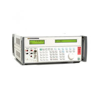
Fluke 5502A Operator's Manual (378 pages)
Multi-Product Calibrator
Brand:
Fluke
| Category:
Test Equipment
| Size: 10.1 MB
Table of Contents
Table of Contents
5
Introduction and Specifications
17
Introduction
19
Safety Information
20
Overload Protection
22
Operation Overview
22
Local Operation
22
Remote Operation (RS-232)
22
Remote Operation (IEEE-488)
23
Instruction Manuals
24
5502A Getting Started Manual
24
5502A Operators Manual
24
Contact Fluke Calibration
24
A Glossary
24
Specifications
25
General Specifications
25
Detailed Specifications
26
DC Voltage
26
DC Current
27
Resistance
28
AC Voltage (Sine Wave)
29
AC Voltage (Sine Wave) (Cont.)
30
AC Current (Sine Wave)
31
AC Current (Sine Wave) (Cont.)
32
Capacitance
33
Temperature Calibration (Thermocouple)
34
Phase
35
Temperature Calibration (RTD)
35
AC and DC Power Specifications
36
Specification Limits for Power and Dual Output Operation
36
Calculate the Uncertainty Specifications of Power and Dual Output Settings
37
Calculate Power Uncertainty
38
Examples of Specified Power Uncertainties at Various Output Settings
38
Additional Specifications
39
Frequency
39
Harmonics (2 Nd to 50 Th )
39
AC Voltage (Non-Sine Wave)
40
AC Voltage (Sine Wave) Extended Bandwidth
40
AC Voltage (Non-Sine Wave) (Cont.)
41
AC Voltage, DC Offset
42
AC Voltage, Square Wave Characteristics
42
AC Voltage, Triangle Wave Characteristics (Typical)
42
AC Current (Non-Sine Wave)
43
AC Current (Non-Sine Wave) (Cont.)
44
AC Current, Square Wave Characteristics (Typical)
44
AC Current, Triangle Wave Characteristics (Typical)
44
Chapter 2 Prepare for Operation
45
Prepare for Operation
45
Introduction
47
Unpack and Inspection
47
Connect to Line Power
48
Select Line Voltage
48
Select Line Frequency
49
Placement
50
Airflow Considerations
51
Features
53
Introduction
55
Front-Panel Features
55
Rear-Panel Features
55
Softkey Menu Trees
55
Chapter 4 Front-Panel Operation
75
Front-Panel Operation
75
Introduction
77
Turn on the Calibrator
77
Use the Setup Menu
78
Use the Instrument Setup Menu
79
Utility Functions Menu
80
Use the NV Memory Menu
80
Use the Softkeys
78
Warm up the Calibrator
78
Reset the Calibrator
81
Zero the Calibrator
81
Operate and Standby Modes
82
Connect the Calibrator to a UUT
83
Recommended Cable and Connector Types
83
When to Use EARTH
84
Four-Wire Versus Two-Wire Connections
85
Compensation off
85
Four-Wire Connection
85
Two-Wire Compensation
85
Cable Connections Instructions
86
RMS Versus P-P Amplitude
91
Auto Range Versus Locked Range
92
Set Output
92
Set DC Voltage Output
93
Set AC Voltage Output
94
Set DC Current Output
97
Set AC Current Output
98
Set DC Power Output
99
Set AC Power Output
101
Set a Dual DC Voltage Output
104
Set a Dual AC Voltage Output
105
Set Resistance Output
108
Set Capacitance Output
109
Set Temperature Simulation (Thermocouple)
111
Set Temperature Simulation (RTD)
113
Measure Thermocouple Temperatures
115
Waveform Types
118
Sine Wave
118
Triangle Waves
118
Square Wave
119
Truncated Sine Wave
119
Set Harmonics
120
Adjust the Phase
121
Record a Phase Angle
123
Record a Power Factor
123
Record a DC Offset
124
Edit and Error Output Settings
125
Edit the Output Setting
125
Show the UUT Error
126
Use Multiply and Divide
127
Set Output Limits
127
Sample Applications
128
How Calibrate an 80 Series Digital Multimeter
129
Cables
129
EARTH Connection
129
Verify the Meter
129
Calibrate the Meter
135
Verify a Model 41 Power Harmonics Analyzer
135
Verify Watts, VA, VAR Performance
135
Verify Harmonics Volts Performance
137
Verify Harmonics Amps Performance
138
Calibrate a Fluke 51 Thermometer
139
Verify the Thermometer
139
Calibrate the Thermometer
140
Chapter 5 Remote Operation
143
Remote Operation
143
Introduction
145
Set up the IEEE-488 Port for Remote Control
147
IEEE-488 Port Setup Procedure
149
Verify the IEEE-488 Port
150
Set up the RS-232 Host Port for Remote Control
151
RS-232 Host Port Setup Procedure
151
Verify the RS-232 Host Port
154
Verify RS-232 Host Port Operation with a Terminal
154
Verify RS-232 Host Port Operation with Visual Basic
156
Set up the RS-232 UUT Port for Remote Control
158
RS-232 UUT Port Setup Procedure
158
Verify the RS-232 UUT Port with RS-232 Host Port
159
Test RS-232 UUT Port Operation with a Terminal
160
Verify RS-232 UUT Port Operation with Visual Basic
161
Verify the RS-232 UUT Port with IEEE-488 Port
161
Change between Remote and Local Operation
163
Local State
163
Local with Lockout State
163
Remote Condition
164
Remote with Lockout Condition
164
RS-232 Interface Overview
165
IEEE-488 Interface Overview
166
Use Commands
169
Types of Commands
169
Common Commands
169
Device-Dependent Commands
169
Interface Messages (IEEE-488)
170
Query Commands
170
Compound Commands
172
Coupled Commands
172
Overlapped Commands
172
Commands Where a Calibration Switch Is Necessary
173
Sequential Commands
173
Commands for RS-232 Only
174
Commands for IEEE-488 Only
175
Command Syntax
175
Parameter Syntax Rules
175
Extra Space or Tab Characters
176
Incoming Character Processing
177
Terminators
177
Response Message Syntax
178
Check 5502A Status
179
Serial Poll Status Byte (STB)
180
Service Request (SRQ) Line
182
Service Request Enable Register (SRE)
182
Programming the STB and SRE
183
Event Status Register (ESR)
183
Bit Assignments for the ESR and ESE
183
Event Status Enable (ESE) Register
183
Program the ESR and ESE
184
Instrument Status Register (ISR)
185
Bit Assignments for the ISR, ISCR, and ISCE
185
Instrument Status Change Enable Registers
185
Instrument Status Change Registers
185
Program the ISR, ISCR, and ISCE
187
Output Queue
187
Error Queue
187
Remote Program Examples
188
Guidelines to Program the Calibrator
188
Write an SRQ and Error Handler
189
Verify a Meter on the IEEE-488 Bus
190
Verify a Meter on the RS-232 UUT Serial Port
190
Use *OPC?, *OPC, and *WAI
190
Get a Thermocouple Measurement
191
Use the RS-232 UUT Port to Control an Instrument
191
Input Buffer Operation
192
Remote Commands
193
Introduction
193
Introduction
195
Command Summary by Function
195
Commands
202
Chapter 7 Maintenance
239
Maintenance
239
Introduction
241
Replace the Mains Power Fuse
241
Replace the Line Fuse
242
Replace the Line Fuse
243
Replace the Current Fuses
244
Clean the Air Filter
245
Clean the Calibrator
246
Performance Tests
246
Accessories
261
Introduction
263
Rack Mount Kit
264
IEEE-488 Interface Cable
264
5500A/Leads
264
Chapter 9 Sc600 Oscilloscope Calibration Option
265
SC600 Oscilloscope Calibration Option
265
Introduction
267
SC600 Oscilloscope Calibration Option Specifications
268
Voltage Function Specifications
268
Edge Specifications
268
Leveled Sine Wave Specifications
269
Time Marker Specifications
269
Wave Generator Specifications
269
Pulse Generator Specifications
270
Trigger Signal Specifications (Pulse Function)
270
Trigger Signal Specifications (Time Marker Function)
270
Trigger Signal Specifications (Edge Function)
270
Trigger Signal Specifications (Square Wave Voltage Function)
270
Trigger Signal Specifications
270
Oscilloscope Input Resistance Measurement Specifications
270
Oscilloscope Input Capacitance Measurement Specifications
270
Overload Measurement Specifications
271
Oscilloscope Connections
271
Start the SC600 Option
271
The Output Signal
272
Adjust the Output Signal
272
Adjust Values with the Rotary Knob
273
Key in a Value
273
Use and
274
Reset the Oscilloscope Option
274
Calibrate the Voltage Amplitude on an Oscilloscope
274
The Volt Function
274
The V/DIV Menu
276
Shortcuts to Set the Voltage Amplitude
276
Amplitude Calibration Procedure for an Oscilloscope
277
Calibrate the Pulse and Frequency Response on an Oscilloscope
278
The Edge Function
278
Pulse Response Calibration Procedure for an Oscilloscope
279
Pulse Response Calibration with a Tunnel Diode Pulser
280
The Leveled Sine Wave Function
280
Shortcuts to Set the Frequency and Voltage
281
The more OPTIONS Menu
282
Sweep through a Frequency Range
283
Frequency Response Calibration Procedure for an Oscilloscope
283
Calibrate the Time Base of an Oscilloscope
285
The Time Marker Function
285
Time Base Marker Calibration Procedure for an Oscilloscope
286
Test the Trigger SC600 Option
287
Test Video Triggers
289
Verify Pulse Capture
290
Measure Input Resistance and Capacitance
291
Input Impedance Measurement
291
Input Capacitance Measurement
291
Test Overload Protection
292
Remote Commands and Queries
293
General Commands
293
Edge Function Commands
297
Marker Function Commands
297
Video Function Commands
298
Overload Function Commands
298
Impedance/Capacitance Function Commands
299
Verification Tables
300
Chapter 10 Sc300 Oscilloscope Calibration Option
319
SC300 Oscilloscope Calibration Option
319
Introduction
321
SC300 Oscilloscope Calibration Option Specifications
322
Volt Function Specifications
322
Edge Function Specifications
323
Leveled Sine Wave Function Specifications
323
Time Marker Function Specifications
324
Oscilloscope Connections
325
The Output Signal
326
Start the Oscilloscope Calibration Option
326
Adjust the Output Signal
327
Adjust Values with the Rotary Knob
327
Key in a Value
327
Reset the Oscilloscope Option
328
Use and
328
Calibrate the Voltage Amplitude on an Oscilloscope
329
The Volt Function
329
The V/DIV Menu
330
Amplitude Calibration Procedure for an Oscilloscope
331
Shortcuts to Set the Voltage Amplitude
331
Calibrate the Pulse and Frequency Response on an Oscilloscope
332
The Edge Function
332
Pulse Response Calibration Procedure for an Oscilloscope
333
The Leveled Sine Wave Function
334
Shortcuts to Set the Frequency and Voltage
335
The more OPTIONS Menu
336
Sweep through a Frequency Range
337
Frequency Response Calibration Procedure for an Oscilloscope
338
Calibrate the Time Base of an Oscilloscope
340
Time Base Marker Calibration Procedure for an Oscilloscope
341
Test the Trigger
342
Summary of Commands and Queries
343
Verification Tables
346
B ASCII and IEEE-488 Bus Codes
365
D Error Messages
373
Advertisement
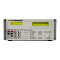
Fluke 5502A Manual (56 pages)
Brand:
Fluke
| Category:
Test Equipment
| Size: 5.03 MB
Table of Contents
Table of Contents
2
Electrical Calibration
4
DC/LF Electrical Calibrators
7
Specialty Calibrators
8
Oscilloscope Calibrators
9
Precision Multimeters
9
Electrical Standards
10
RF References
12
Temperature Calibration
13
Standard Platinum Resistance Thermometers
20
Fixed-Point Cells
20
Cell Maintenance Apparatus
21
Thermometer Readouts
22
Reference Prts
23
Thermocouples
23
Thermistors
23
Compact Calibration Baths
24
Standard Calibration Baths
24
Special Application Baths
25
Bath Controllers
25
Metrology Wells
25
Field Metrology Wells
25
Dual-Block Dry-Well
26
Field Dry-Well Calibrators
26
Micro-Baths
26
Portable Calbration Baths
26
Handheld Calibrators
26
Infrared Calibrators
27
Zero-Point Dry-Well
27
Surface Probe Calibrator
27
Thermocouple Furnaces
27
Humidity Calibration
28
Humidity Calibrators
29
Pressure Calibration
30
Gas Pressure Controllers/Calibrators
34
Series Piston Gauges
34
High Pressure Controllers/Calibrators
35
Reference Pressure Indicators
35
2400 Series Piston Gauges
36
Specialty Piston Gauges
37
Manual Pressure Generation and Control
37
Industrial Deadweight Testers
38
Pressure Comparators
38
Pressure Calibrators
39
Air Data Calibration
40
Pressure Calibration Systems
40
Gas Flow Calibration
41
Gas Flow Standards
42
Calibration Software
43
Electrical and RF Calibration Software
45
Calibration Asset Management Software
45
Software Support Programs
45
Temperature Calibration Software
46
Pressure/Flow Calibration Software
47
Data Acquisition
48
2638A Hydra Series III Data Acquisition System
49
Fluke DAQ 6.0 Application Software
49
Service Programs
52
Training
53
Advertisement
Related Products
FLUKE 5500A
Fluke 5502E
Fluke 5500E
Fluke 5514B-70M
Fluke 5522A-PQ
Fluke 5522A-PQ/1G
Fluke 5522A-PQ/6
Fluke 5550A
Fluke 5540A
Fluke 5592405
Fluke Categories
Measuring Instruments
Test Equipment
Multimeter
Thermometer
Laboratory Equipment
More Fluke Manuals
Login
Sign In
OR
Sign in with Facebook
Sign in with Google
Upload manual
Upload from disk
Upload from URL