Sign In
Upload
Manuals
Brands
Fluke Manuals
Test Equipment
5522A-PQ/1G
Fluke 5522A-PQ/1G Manuals
Manuals and User Guides for Fluke 5522A-PQ/1G. We have
1
Fluke 5522A-PQ/1G manual available for free PDF download: Operator's Manual
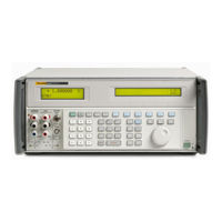
Fluke 5522A-PQ/1G Operator's Manual (426 pages)
Multi-Product Calibrator
Brand:
Fluke
| Category:
Test Equipment
| Size: 13.11 MB
Table of Contents
Table of Contents
5
Introduction
23
Safety Information
24
Overload Protection
25
Operation Overview
25
Local Operation
25
Remote Operation (RS-232)
26
Remote Operation (IEEE-488)
26
Where to Go from here
27
Instruction Manuals
27
5522A Getting Started Manual
27
5522A Operators Manual
27
General Specifications
28
Detailed Specifications
29
DC Voltage
29
DC Current
29
Resistance
31
AC Voltage (Sine Wave)
32
AC Current (Sine Wave)
34
Capacitance
36
Temperature Calibration (Thermocouple)
37
Temperature Calibration (RTD)
38
DC Power Specification Summary
38
Power and Dual Output Limit Specifications
39
Phase
40
Additional Specifications
41
Frequency
41
Harmonics (2 Nd to
41
AC Voltage (Sine Wave) Extended Bandwidth
42
AC Voltage (Non-Sine Wave)
42
AC Voltage, DC Offset
44
AC Voltage, Square Wave Characteristics
44
AC Voltage, Triangle Wave Characteristics
44
AC Current (Non-Sine Wave)
44
AC Current, Square Wave Characteristics
45
AC Current, Triangle Wave Characteristics
45
Preparing for Operations
47
Introduction
49
Unpack and Inspect
49
How to Replace the Mains Power Fuse
49
How to Select Line Voltage
50
How to Connect to Line Power
50
How to Select Line Frequency
50
How to Contact Fluke
52
Placement
53
Cooling Considerations
53
Features
55
Introduction
57
Front-Panel Features
57
Rear-Panel Features
57
Softkey Menu Trees
57
Front Panel Operation
77
Introduction
79
How to Turn on the Calibrator
79
Warming up the Calibrator
80
How to Use the Softkeys
80
How to Use the Setup Menu
80
How to Use the Instrument Setup Menu
81
How to Use the Setup Menu
81
Utility Functions Menu
82
How to Use the NV Memory Menu
82
How to Reset the Calibrator
83
How to Zero the Calibrator
83
Operate and Standby Modes
84
How to Connect the Calibrator to a UUT
84
Recommended Cable and Connector Types
85
When to Use EARTH and EXGRD
85
Earth
85
How to Connect the Calibrator to a UUT
85
External Guard
86
Four-Wire Versus Two-Wire Connections
86
Four-Wire Connection
86
Two-Wire Compensation
86
Compensation off
86
Cable Connections Instructions
86
RMS Versus P-P Amplitude
92
Auto Range Versus Locked Range
93
How to Set Output
93
How to Set DC Voltage Output
94
How to Set AC Voltage Output
95
How to Set Output
95
How to Set DC Voltage Output
95
How to Set DC Current Output
95
How to Set AC Current Output
95
How to Set DC Power Output
95
How to Set AC Power Output
95
How to Set Capacitance Output
95
How to Set DC Current Output
98
How to Set AC Current Output
99
How to Set DC Power Output
100
How to Set AC Power Output
102
How to Set a Dual DC Voltage Output
105
How to Set a Dual AC Voltage Output
106
How to Set Resistance Output
109
How to Set Capacitance Output
110
How to Set Temperature Simulation (Thermocouple)
111
How to Set Temperature Simulation (RTD)
114
How to Measure Thermocouple Temperatures
115
Waveform Types
117
Sine Wave
117
Triangle Waves
118
Square Wave
118
Truncated Sine Wave
119
How to Set Harmonics
119
How to Adjust the Phase
120
How to Adjust the Phase
121
How to Enter a Phase Angle
122
How to Enter a Power Factor
122
How to Enter a DC Offset
123
Editing and Error Output Settings
124
How to Edit the Output Setting
124
How to Display the UUT Error
125
How to Use Multiply and Divide
126
How to Set Output Limits
126
How to Set Voltage and Current Limits
126
How to Measure Pressure
127
How to Synchronize the Calibrator Using 10 Mhz IN/OUT
128
How to Use an External 10 Mhz Clock
128
How to Source AC Current and Parallel-Connected 5522As
129
How to Synchronize the Calibrator Using 10 Mhz IN/OUT
129
Three-Phase Power Calibration
130
Sample Applications
131
How Calibrate an 80 Series Digital Multimeter
131
Three-Phase Power Calibration
131
Cables
132
EARTH Connection
132
How to Test the Meter
132
How to Calibrate the Meter
136
How to Test a Model 41 Power Harmonics Analyzer
136
How to Test Watts, VA, VAR Performance
136
How to Test Harmonics Volts Performance
138
How to Test Harmonics Amps Performance
139
How to Calibrate a Fluke 51 Thermometer
140
How to Test the Thermometer
140
How to Calibrate the Thermometer
141
Remote Operations
143
Introduction
145
How to Set up the IEEE-488 Port for Remote Control
147
IEEE-488 Port Setup Procedure
149
How to Test the IEEE-488 Port
149
How to Set up the RS-232 Host Port for Remote Control
151
RS-232 Host Port Setup Procedure
151
How to Test the RS-232 Host Port
153
How to Test RS-232 Host Port Operation with a Terminal
154
How to Test RS-232 Host Port Operation with Visual Basic
156
How to Set up the RS-232 UUT Port for Remote Control
157
RS-232 UUT Port Setup Procedure
157
How to Test the RS-232 UUT Port Via RS-232 Host Port
158
How to Test RS-232 UUT Port Operation Via a Terminal
159
How to Test RS-232 UUT Port Operation with Visual Basic
160
How to Test the RS-232 UUT Port Via IEEE-488 Port
160
How to Change between Remote and Local Operation
162
Local State
162
Local with Lockout State
162
Remote State
162
Remote with Lockout State
163
RS-232 Interface Overview
163
Local with Lockout State
163
IEEE-488 Interface Overview
164
IEEE-488 Interface Overview
165
How to Use Commands
167
Types of Commands
167
Device-Dependent Commands
167
Common Commands
167
Query Commands
167
Interface Messages (IEEE-488)
168
Compound Commands
169
Coupled Commands
170
Overlapped Commands
170
Sequential Commands
171
Commands that Require the Calibration Switch
171
Commands for RS-232 Only
171
Commands for IEEE-488 Only
172
Command Syntax
172
Parameter Syntax Rules
172
Extra Space or Tab Characters
174
Terminators
174
Incoming Character Processing
175
Response Message Syntax
175
Checking 5522A Status
176
Serial Poll Status Byte (STB)
176
Service Request Enable Register (SRE)
176
Event Status Register (ESR)
176
Event Status Enable (ESE) Register
176
Serial Poll Status Byte (STB)
177
Instrument Status Change Registers
178
Instrument Status Change Enable Registers
178
Service Request (SRQ) Line
179
Service Request Enable Register (SRE)
179
Programming the STB and SRE
179
Event Status Register (ESR)
180
Event Status Enable (ESE) Register
180
Bit Assignments for the ESR and ESE
180
Programming the ESR and ESE
181
Instrument Status Register (ISR)
182
Instrument Status Change Registers
182
Instrument Status Change Enable Registers
182
Bit Assignments for the ISR, ISCR, and ISCE
182
Programming the ISR, ISCR, and ISCE
183
Output Queue
184
Error Queue
184
Remote Program Examples
184
Guidelines for Programming the Calibrator
184
Writing an SRQ and Error Handler
185
Verifying a Meter in the IEEE-488 Bus
186
Verifying a Meter on the RS-232 UUT Serial Port
186
Using *OPC?, *OPC, and *WAI
186
Taking a Thermocouple Measurement
187
Taking a Pressure Measurement
187
Using the RS-232 UUT Port to Control an Instrument
188
Input Buffer Operation
188
Remote Commands
189
Introduction
191
Command Summary by Function
191
Commands
198
Maintenance
239
Introduction
241
How to Replace the Line Fuse
241
How to Replace the Current Fuses
242
How to Clean the Air Filter
243
General Cleaning
244
Performance Tests
245
Accessories
259
Introduction
261
Rack Mount Kit
262
IEEE-488 Interface Cable
262
Null-Modem Cables
262
5520A-525A/Leads
262
SC600 Oscilloscope Calibration Option
263
Introduction
265
SC600 Oscilloscope Calibration Option Specifications
265
General Specifications
266
Voltage Function Specifications
266
Edge Specifications
266
Leveled Sine Wave Specifications
267
Time Marker Specifications
267
Wave Generator Specifications
267
Pulse Generator Specifications
268
Trigger Signal Specifications (Pulse Function)
268
Trigger Signal Specifications (Time Marker Function)
268
Trigger Signal Specifications (Edge Function)
268
Trigger Signal Specifications (Square Wave Voltage Function)
268
Trigger Signal Specifications
268
Oscilloscope Input Resistance Measurement Specifications
268
Oscilloscope Input Capacitance Measurement Specifications
268
Overload Measurement Specifications
269
Oscilloscope Connections
269
How to Start the SC600 Option
269
The Output Signal
270
How to Adjust the Output Signal
270
How to Key in a Value
270
How to Adjust Values with the Rotary Knob
271
How to Use and
272
How to Reset the Oscilloscope Option
272
How to Calibrat the Voltage Amplitude on an Oscilloscope
272
The Volt Function
272
The V/DIV Menu
273
Shortcuts to Set the Voltage Amplitude
273
Amplitude Calibration Procedure for an Oscillosope
273
How to Calibrate the Pulse and Frequency Response on an Oscilloscope
274
The Edge Function
275
Pulse Response Calibration Procedure for an Oscilloscope
275
Pulse Response Calibration with a Tunnel Diode Pulser
276
The Leveled Sine Wave Function
277
Shortcuts for Setting the Frequency and Voltage
278
The more OPTIONS Menu
278
How to Sweep through a Frequency Range
279
Frequency Response Calibration Procedure for an Oscilloscope
280
How to Calibrate the Time Base of an Oscilloscope
281
The Time Marker Function
281
Time Base Marker Calibration Procedure for an Oscilloscope
282
How to Test the Trigger SC600 Option
283
How to Test Video Triggers
284
How to Verify Pulse Capture
285
How to Measure Input Resistance and Capacitance
286
Input Impedance Measurement
286
Input Capacitance Measurement
286
How to Test Overload Protection
287
Remote Commands and Queries
288
General Commands
288
Edge Function Commands
292
Marker Function Commands
292
Video Function Commands
293
Overload Function Commands
293
Impedance/Capacitance Function Commands
294
Verification Tables
295
DC Voltage Verification
295
AC Voltage Amplitude Verification
296
AC Voltage Frequency Verification
297
Wave Generator Amplitude Verification: 50 Ω Output Impedance
299
Leveled Sine Wave Verification: Amplitude
300
Leveled Sine Wave Verification: Frequency
301
Leveled Sine Wave Verification: Harmonics
301
Leveled Sine Wave Verification: Flatness
302
Edge Verification: Amplitude
310
Edge Verification: Frequency
310
Edge Verification: Duty Cycle
311
Edge Verification: Rise Time
311
Tunnel Diode Pulser Verification
311
Marker Generator Verification
312
Pulse Generator Verification: Period
312
Pulse Generator Verification: Pulse Width
312
Input Impedance Verification: Resistance
313
Input Impedance Verification: Capacitance
313
SC1100 Oscilloscope Calibration Option
315
SC1100 Option Specifications
317
General Specifications
317
Introduction
317
Volt Specifications
318
Edge Specifications
319
Leveled Sine Wave Specifications
319
Time Marker Specifications
320
Wave Generator Specifications
320
Pulse Generator Specifications
321
Trigger Signal Specifications (Pulse Function)
321
Trigger Signal Specifications (Time Marker Function)
321
Oscilloscope Connections
322
How to Start the SC1100 Option
322
The Output Signal
323
How to Adjust the Output Signal
323
How to Key in a Value
323
How to Adjust Values with the Rotary Knob
324
How to Reset the SC1100 Option
325
How to Use X and D
325
How to Calibrate the Voltage Amplitude on an Oscilloscope
325
The VOLT Function
325
The V/DIV Menu
326
Oscilloscope Amplitude Calibration Procedure
326
How to Calibrate the Pulse and Frequency Response on an Oscilloscope
327
The Edge Function
328
Oscilloscope Pulse Response Calibration Procedure
328
The Leveled Sine Wave Function
330
Shortcuts for Setting the Frequency and Voltage
331
The more OPTIONS Menu
331
How to Sweep through a Frequency Range
332
Oscilloscope Frequency Response Calibration Procedure
333
How to Calibrate the Time Base of an Oscilloscope
334
The Time Marker Function
335
Time Base Marker Calibration Procedure for an Oscilloscope
336
How to Test the Trigger Functions of an Oscilloscope
337
How to Test Video Triggers
338
How to Verify Pulse Capture
339
How to Measure Input Resistance and Capacitance
340
Input Impedance Measurement
340
Input Capacitance Measurement
341
How to Test Overload Protection
341
Remote Commands and Queries
343
Edge Function Commands
346
Marker Function Commands
346
Video Function Commands
347
Overload Function Commands
347
Impedance/Capacitance Function Commands
348
Verification Tables
349
DC Voltage Verification
349
AC Voltage Verification
351
AC Voltage Frequency Verification
352
Wave Generator Amplitude Verification: 1 MΩ Output Impedance
353
Edge Verification: Amplitude
355
Edge Verification: Frequency
356
Edge Verification: Duty Cycle
356
Edge Verification: Rise Time
356
Leveled Sinewave Verification: Amplitude
357
Tunnel Diode Pulser Verification
357
Leveled Sinewave Verification: Frequency
358
Leveled Sinewave Verification: Harmonics
358
Leveled Sinewave Verification: Flatness
360
Marker Generator Verification
367
Pulse Generator Verification: Period
368
Pulse Generator Verification: Pulse Width
368
Input Impedance Verification: Resistance
369
Input Impedance Verification: Capacitance
369
PQ Option
371
5522A PQ Specifications
373
5522A PQ Option Specifications
373
Composite Harmonic Function Specifications
373
Introduction
373
AC Voltage Specifications
374
AC Voltage Auxiliary Specifications (Dual Output Mode Only)
375
AC Current Specifications, LCOMP off
375
AC Current Specifications, LCOMP off (Continued)
376
AC Current Specifications, LCOMP on
376
Flicker Simulation Mode
377
Sags & Swells Simulation Mode
377
Phase Specifications, Sinewave Outputs
377
Composite Harmonics Function (Volts)
378
How to Enter the PQ Modes
378
How to Create Composite Harmonic Waveforms
378
The Wave Selection Menus
378
Recall Wave
379
Save Wave
379
New Wave
379
Edit Wave
379
How to Create New Waves
379
Harmonic Number
380
Harmonic Amplitude
380
Phase
380
How to Edit Waves
381
How to Save Waves
381
How to Recall Saved Waves
382
Preinstalled Waves
382
IEC Waves
382
NRC Waves
383
How to Recall Preinstalled IEC Waves
383
How to Recall Preinstalled NRC Waves
383
Composite Harmonics Function (Amps)
383
How to Set LCOMP
384
Output aux
384
Composite Harmonics Function (Volts and Amps)
385
How to Set LCOMP
385
Output aux
385
Φ & REF Menus
386
Composite Harmonics Function (Volts and Volts)
386
Φ & REF Menus
387
Delta (Δ)Amplitude, Flicker Function (Volts)
387
Delta (Δ) Amplitude Mode (Volts)
387
How to Select the Flicker Function
387
How to Set the Repeat Frequency
387
How to Set the Modulation Pattern
387
How to Set the Flicker Amplitude
388
PST Values
388
How to Set Phase and Reference in the ΔAMPL Function
388
Delta (Δ) Amplitude, Flicker Function (Current)
388
Delta (Δ) Amplitude Mode (Amps)
388
More Information
389
Delta (Δ) Amplitude, Single (Sags & Swells) Function (Volts)
389
Delta (Δ) Amplitude Mode (Volts)
389
How to Set the Ramp-Up Period
389
How to Set the Sag & Swell Width
389
How to Set the Sag/Swell Amplitude
389
How to Set Triggers
390
Example
390
Delta (Δ) Amplitude, Single (Sags & Swells) Function (Current)
390
Delta (Δ) Amplitude Mode (AMPS)
390
How to Set Triggers
391
How to Set the Ramp-Up Period
391
How to Set the Sag/Swell Width
391
How to Set the Sag/Swell Amplitude
391
Delta (Δ)Amplitude Mode (Volts and Amps)
391
Example
391
Remote Commands
392
Commands
392
Example Strings
397
Performance Tests
398
Verification Table
398
Advertisement
Advertisement
Related Products
Fluke 5522A Operators
Fluke 5522A-PQ
Fluke 5522A/1GHZ
Fluke 5522A-PQ/6
Fluke 5520A Service
FLUKE 5500A
Fluke 5502E
Fluke 5502A
Fluke 5514B-70M-EP
Fluke 5500E
Fluke Categories
Measuring Instruments
Test Equipment
Multimeter
Thermometer
Laboratory Equipment
More Fluke Manuals
Login
Sign In
OR
Sign in with Facebook
Sign in with Google
Upload manual
Upload from disk
Upload from URL