Table of Contents
Advertisement
Quick Links
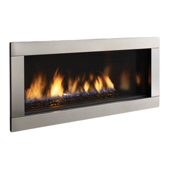
Regency Horizon ™ HZ40E
Horizon HZ40E Product Video
WARNING
FIRE OR EXPLOSION HAZARD
Failure to follow safety warnings exactly could result in serious
injury, death, or property damage.
- Do not store or use gasoline or other flammable vapors and liquids in the vicinity of this or any other
appliance.
- WHAT TO DO IF YOU SMELL GAS
•
Do not try to light any appliance.
• Do not touch any electrical switch: do not use any phone in your building.
Leave the building immediately.
• Immediately call your gas supplier from a neighbour's phone. Follow the gas supplier's
instructions.
• If you cannot reach you gas supplier, call the fire department.
- Installation and service must be performed by a qualified installer, service agency or the gas supplier.
Tested by:
919-360
FPI FIREPLACE PRODUCTS INTERNATIONAL LTD. 6988 Venture St., Delta, BC Canada, V4G 1H4
Gas Fireplace
Installer: Please complete the details on the back cover
and leave this manual with the homeowner.
Homeowner: Please keep these instructions for future reference.
Owners &
Installation Manual
40E
MODELS:
HZ
-NG10 Natural Gas
40E
HZ
-LP10 Propane
www.regency-fire.com
09.09.14
Advertisement
Table of Contents

Related Manuals for Regency Fireplace Products Horizon HZ40E-NG10


Summary of Contents for Regency Fireplace Products Horizon HZ40E-NG10
- Page 1 Regency Horizon ™ HZ40E Owners & Installation Manual Gas Fireplace MODELS: -NG10 Natural Gas -LP10 Propane www.regency-fire.com Horizon HZ40E Product Video WARNING FIRE OR EXPLOSION HAZARD Failure to follow safety warnings exactly could result in serious injury, death, or property damage.
-
Page 2: Manufactured Mobile Home Requirements
Manufactured Home Construction and Safety Standard, Title 24 CFR, Part 3280, in the Untied States, or the Standard for Installation in Mobile Homes, CAN/CSA Z240 MH, in Canada. Regency Horizon Gas Inserts Video Regency Horizon™ HZ40E-10 Gas Fireplace... - Page 3 To the New Owner: Congratulations! You are the owner of a state-of-the-art Gas Fireplace by REGENCY . The HZ40E has been ® designed to provide you with all the warmth and charm of a fireplace at the flick of a switch. The model HZ40E has been approved by Warnock Hersey/Intertek for both safety and efficiency.
-
Page 4: Table Of Contents
Vertical Terminations Rigid Pipe 4" x 6-5/8" ....32 Valve assembly Replacement ........57 Venting Arrangements - Vertical Terminations ....34 Main Assembly ............58 Unit Installation with Horizontal Termination ....35 Accessories ..............59 4" x 6-5/8" venting ............35 The Warranty: Limited Lifetime ........63 Regency Horizon™ HZ40E-10 Gas Fireplace... -
Page 5: Copy Of Safety Decal
The State of Massachusetts requires the installation of a carbon monoxide alarm in accordance with NFPA 720 and a CO alarm with battery back up in the same room where the gas appliance is installed. Regency Horizon™ HZ40E-10 Gas Fireplace... -
Page 6: Ma Code - Co Detector
(e) A copy of all installation instructions for all Product Approved side wall horizontally vented gas fueled equipm ent, all venting instructions, all parts lists for venting instructions, and/or all venting design instructions shall remain with the appliance or equipment at the completion of the installation. Regency Horizon™ HZ40E-10 Gas Fireplace... - Page 7 (1092mm) (972mm) (902mm) Inner/Outer Faceplate 4 Piece Faceplate/Verona Surround Regency Horizon™ HZ40E-10 Gas Fireplace...
-
Page 8: Important Message
National Electrical Code, ANSI/NFPA 70 or CSA C22.1 Canadian Electrical Code. 3. See general construction and assembly instructions. The appliance and vent should be enclosed. Regency Horizon™ HZ40E-10 Gas Fireplace... -
Page 9: Installation Checklist
Corner customer. the fireplace to be operated with less heat entering the room. The kit may be used on either the left or right side. Regency Horizon™ HZ40E-10 Gas Fireplace... -
Page 10: Clearances
Passing through wall/ floor/ceiling - when 1-1/2" G: From Floor 27" (686mm) Top of Fireplace Opening firestop is used. Note: 0" No hearth required Installed Close to Floor Installed close to ceiling. Alcove 10 | Regency Horizon™ HZ40E-10 Gas Fireplace... -
Page 11: Mantel Clearances
To Unit 27” Base Top of Fireplace Opening MANTEL LEG CLEARANCES Combustible mantel leg clearances as per diagram: 5-11/16”(144mm) MANTEL LEG Non-Combustible 1.5" (38mm) 7-1/8” (181mm) Allowable mantel legp rojection 10” ( 203mm) 13”( 279mm) Regency Horizon™ HZ40E-10 Gas Fireplace... -
Page 12: Unit Assembly Prior To Installation
3. Install any optional components with access panel removed. 4. Reinstall access panel with 8 screws - prior to installing any facing material Note: Access panel is no longer usable once facing material installed. Installation Access Panel 12 | Regency Horizon™ HZ40E-10 Gas Fireplace... -
Page 13: Framing Dimensions
Framing depth measurement is noted with the nailing strips set as far forward on the firebox as possible. The nailing strips can be adjusted back up to 3-1/4” to allow for varying thicknesses in non-combustible material & wall finishes. Regency Horizon™ HZ40E-10 Gas Fireplace... -
Page 14: Optional Framing Kit
NOTE: Ensure the flat side of the steel stud is facing the wood framing. 9. Secure 2 vertical studs on either side of the appliance with 4 screws per side stud as shown. Vertical studs Flat side out 14 | Regency Horizon™ HZ40E-10 Gas Fireplace 919-430 08/26/14... -
Page 15: Wall Mount On / Off Switch And Remote Receiver Installation
11. Using the two (2) screws provided secure the cover plate to the Receiver. Low Voltage Junction Box Profl ame Receiver J-Box Receiver Slider Switch Wall Plate 10 ft. wire harness with 12 pin connector Diagram 1 Regency Horizon™ HZ40E-10 Gas Fireplace... -
Page 16: Non-Combustible Requirements
6. Prime wall for a second time for proper adhesion of paint 7. Paint walls using a high quality paint which will withstand Non-combustible board-faces and edges the high temperatures being emitted from this appliance. MUST BE PRIMED. 16 | Regency Horizon™ HZ40E-10 Gas Fireplace... -
Page 17: Framing & Finishing
IMPORTANT: 1/2" gap is required between the faceplate and the finished Unit shown with inner door frame only wall when using 4 piece Faceplate (Part # 258-954, 258-957) or Verona Glass Surround (Part # 256-951, 256-957) Regency Horizon™ HZ40E-10 Gas Fireplace... - Page 18 While every precaution is taken in providing the recommendations on preparation and finish, given the variations in paint quality, with temperature limits and workmanship in application, Regency is unable to guarantee the life of the joint compounds, paint or any other finish materials or workmanship applied to or used in any application surrounding the fireplace.
-
Page 19: Exterior Vent Termination Requirements
* Clearance in accordance with local installation codes and the requirements of the gas supplier 3 feet (91cm) within a height of 15 feet (4.5m) above the meter / regulator assembly 3 feet (91cm) above - if within 10 feet (3m) horizontally Regency Horizon™ HZ40E-10 Gas Fireplace... -
Page 20: 4" X 6-5/8" Rigid Pipe
4” X 6- 5/8” RIGID PIPE CROSS REFERENCE CHART Components from different Manufacturers may not be mixed. Not All Rigid Pipe components are available directly from FPI. Components from different Manufacturers may not be mixed. Not all rigid pipe components are available directly from Regency. Description... - Page 21 Never allow the vent to run downward - this could cause high temperatures and may present a possible fi re hazard. Regency Fireplace Products . 6988 Venture St. . Delta, BC . Canada . V4G 1H4 . 604-946-5155 . www.regency-fi re.com...
-
Page 22: Vent Restrictor Position
4. Once the vent restrictor plate is in the required position, secure with screws. Set 0 Set 1 Set 2 Set 3 (Factory set) VENT RESTRICTOR VENT RESTRICTOR VENT RESTRICTOR VENT RESTRICTOR AT 2" AT 1-1/2" AT 1" AT 3" 22 | Regency Horizon™ HZ40E-10 Gas Fireplace... -
Page 23: Venting Introduction
Refer to the "Vent Restrictor Position" section for details on how to change the vent restrictor from the factory setting of Set 0 to Set 1 if required. Note: For horizontal terminations the Regency Direct Vent Flex System may be used for installations with a maximum continuous vent length of up to 10 feet. -
Page 24: Horizontal Terminations Flex Vent 4" X 6-7/8
S.S. screws #8 x 1-1/2” drill point Notes: 1. Liner sections should be continuous without any joints or seams. 2. Only Flex pipe purchased from Regency may be ® used for Flex installations 3. Horizontal vent must be supported every 3 feet. -
Page 25: Horizontal Terminations Rigid Pipe 4" X 6-5/8
American Metal Products Ameri Vent Direct Vent, Security Secure Vent , ICC Excel, Selkirk Direct-Temp. AstroCap is a proprietary trademark of FPI ® Fireplace Products International Ltd. Dura-Vent® and Direct Vent are registered and/or proprietary trademarks of Simpson Dura-Vent Co. Inc. Regency Horizon™ HZ40E-10 Gas Fireplace... -
Page 26: Horizontal Terminations Rigid Pipe 4" X 6-5/8
Flex system can only be used up to 10 feet - otherwise rigid venting must be used. Straight Out Horizontal Venting Diagram 1 center of hole Please note the minimum centerline for basic install shown above. 26 | Regency Horizon™ HZ40E-10 Gas Fireplace... - Page 27 3' Max. 4' Min. 6' Max. Please note minimum 4' Max. 6' Min. 7' Max. 1 foot between 90 elbows is required. 5' Max. 8' Min. 8' Max. Restrictor Position - Set 0 (factory setting) Regency Horizon™ HZ40E-10 Gas Fireplace...
- Page 28 1 f o o t 6' Min. 5' Max. 10' Min. 8' Max. between 90 elbows 7' Min. 6' Max. 12' Min. 9' Max. is required. Restrictor Position - Set 0 (factory setting) 28 | Regency Horizon™ HZ40E-10 Gas Fireplace...
-
Page 29: Vertical Terminations Rigid Pipe 4" X 6-5/8
American Metal Products Ameri Vent Direct Vent, Security Secure Vent , ICC Excel, Selkirk Direct-Temp. AstroCap is a proprietary trademark of FPI ® Fireplace Products International Ltd. Dura-Vent® and Direct Vent are registered and/or proprietary trademarks of Simpson Dura-Vent Co. Inc. Regency Horizon™ HZ40E-10 Gas Fireplace... -
Page 30: Venting Arrangement For Vertical Terminations
Set 0 to Set 1 or Set 2 if required. Vent Restrictor on Set 2 Vent Restrictor on Set 1 Max. 10’ (3m)(centerline to centerline) Minimum length of pipe between elbows 12” (305mm) 30 | Regency Horizon™ HZ40E-10 Gas Fireplace... -
Page 31: Vertical Termination With Co-Linear Flex System
46DVA-VCH High Wind Cap 46DVA-GK 3" Co-linear Adapter with flashing Outer Pipe with Kit# 946-563 Air Intake Pipe Length Co-Linear Flex Rigid Pipe Adapter Adapter # 510-994 with Kit# 946-563 45 Elbow Inner Pipe Adapter with Kit# 946-563 Regency Horizon™ HZ40E-10 Gas Fireplace... -
Page 32: Vertical Terminations Rigid Pipe 4" X 6-5/8
6' Max. 6' Min. Restrictor Position - Set 0 (factory setting) Restrictor Position - Set 0 (factory setting) For additional vertical venting with 2 x 90 elbows, refer to "Rigid Pipe Venting Arrangements" Section. 32 | Regency Horizon™ HZ40E-10 Gas Fireplace... - Page 33 Please note min. 1 foot 5' Min. 6' Max. 8' Min. between 90 elbows is 6' Min. 7' Max. 9' Min. required. 7' Min. 8' Max. 10' Min. Restrictor Position - Set 0 (factory setting) Regency Horizon™ HZ40E-10 Gas Fireplace...
-
Page 34: Venting Arrangements - Vertical Terminations
Horizontal Distance (Feet) Horizontal Distance (Feet) Horizontal Distance (Feet) The shaded area in the diagrams show the allowable vertical terminations when using two- 3" co-linear aluminium flex and 4 x 6-5/8" rigid pipe. 34 | Regency Horizon™ HZ40E-10 Gas Fireplace... -
Page 35: Unit Installation With Horizontal Termination
3 supplied screws (drilling pilot holes will make this easier). 4. Level the fireplace and fasten it to the framing Diagram 2 using nails or screws through the top and side nailing strips. Diagram 7 Diagram 1 Regency Horizon™ HZ40E-10 Gas Fireplace... -
Page 36: Unit Installation With Horizontal Termination
(10" (254mm) and slip it over the outer flue collar of the vent Outer Diameter) terminal at least 1-3/8"(35mm) and fasten with the 3 screws. 36 | Regency Horizon™ HZ40E-10 Gas Fireplace... -
Page 37: Unit Installation With Vertical Termination
Note that for steep roof pitches, the vertical height must be increased. A poor draft, or down drafting can result from high wind conditions near big trees or adjoining roof lines, in these cases, increasing the vent height may solve the problem. Regency Horizon™ HZ40E-10 Gas Fireplace... -
Page 38: High Elevation
Note: Any damage due to carboning resulting screw (clockwise) with a 1/8" flat screwdriver. from improperly setting the aeration Note: Screw should be snug, but do not over controls is NOT covered under warranty. tighten. 38 | Regency Horizon™ HZ40E-10 Gas Fireplace... -
Page 39: Wiring Diagram
CAUTION: Label all wires prior to disconnection Caution: Ensure that the wires do not touch any when servicing controls. Wiring errors can cause hot surfaces and are away from sharp edges. improper and dangerous operation. 1 of 10 Regency Horizon™ HZ40E-10 Gas Fireplace... -
Page 40: Optional Fan Installation - Initial Install
Remove 2 top screws and loosen 2 bottom screws to remove the side access pane Tabs 3) Secure the fan to the fl oor of the unit with 2 screws, in locations show below. 919-405 06/26/14 40 | Regency Horizon™ HZ40E-10 Gas Fireplace... - Page 41 Fan Control Module marked “COM”. Turn the switch on the Fan Control Module to the ON position. ON is to the left. The “O” is the off position FCM-COM connector 919-405 05/20/14 Regency Horizon™ HZ40E-10 Gas Fireplace...
-
Page 42: Optional Fan Installation - Existing Install
8) Remove the burner by sliding it to the right - then lift out. * Prior to removing burner - remove crystals, pebbles, spa stones and inner panels - if installed. 919-405 06/26/14 42 | Regency Horizon™ HZ40E-10 Gas Fireplace... - Page 43 The “O” is the off position 14.. Secure the ground wire from the fan assembly and the power cord to the ground lug located on the back left near the fan. 919-405 05/20/14 Regency Horizon™ HZ40E-10 Gas Fireplace...
-
Page 44: Wiring Diagram With Optional Fan
Caution: Ensure that the wires do not touch any hot surfaces and are away from sharp edges. CAUTION: Label all wires prior to disconnection when servicing controls. Wiring errors can cause improper and dangerous operation. 44 | Regency Horizon™ HZ40E-10 Gas Fireplace... -
Page 45: Inner Panel Installation
6) Install the back enamel panel fi rst. Tilt the panel forward - position the bottom of the panel fi rst. Use care not to scratch or mar the panel on the pilot shield. Final Install Regency Horizon™ HZ40E-10 Gas Fireplace 05/20/14 919-076b... -
Page 46: Glass Crystals Or Optional Stones
5 lbs 5 lbs 2 packages (6 x bags pebbles) Natural River Pebbles shown surrounding the Horizon Burner Glass Crystals shown surrounding the Burner Optional Volcanic Stones + Glass Crystals shown on burner. 46 | Regency Horizon™ HZ40E-10 Gas Fireplace... -
Page 47: Optional Driftwood Log Set Installation
Ensure L and R sides are in the correct position. Secure template in place with magnets (supplied) on each side. HZ40E - log placement template - HZ54E - existing Pilot HZ54E - new Pilot shown in place. Hood Hood Regency Horizon™ HZ40E-10 Gas Fireplace 05/14/13 919-258a... - Page 48 13. Position Right Log (5) by lining pin on Logs 1 with pin landing on Log 3, match bottom of Log 5 and template profi le. 14. Carefully remove log placement template. Match pin and pin landing Logs 1 and 3. HZ40E shown - Completed Install 48 | Regency Horizon™ HZ40E-10 Gas Fireplace 919-258a 05/14/13...
-
Page 49: Glass Door Installation
See Diagram 2. Diagram 3 Diagram 1 Hook top of door onto top flange Flush Door Diagram 2 Regency Horizon™ HZ40E-10 Gas Fireplace... -
Page 50: Mesh Barrier Removal / Installation
7. Secure the assembly with screws on each side as shown below. 3. Install screen into inner door trim (3). Secure screen by bending down the 6 tabs as shown Tabs Regency Horizon™ HZ40E-10 Gas Fireplace 50 | Regency Horizon™ HZ40E-10 Gas Fireplace... -
Page 51: Piece Faceplate Installation
Important: 1/2" gap required between faceplate and fi nished wall when using part #256-924, 256-926, 256- 927 (4 pc. faceplate). +1/2" +1/4" Use fi rst notch in bracket Final Install for standard installation 08/22/11 919-073 Regency Horizon™ HZ40E-10 Gas Fireplace... -
Page 52: Inner And Outer Door Frame Installation
Inner door frame may be installed by itself, or with the outer door frame. The outer door frame cannot be installed by itself - if install- ing the outer door frame - the inner door frame must also be installed. 08/24/11 918-905a 52 | Regency Horizon™ HZ40E-10 Gas Fireplace... -
Page 53: Operating Instructions
Use a non-abrasive cleaner and DO NOT ATTEMPT TO CLEAN THE GLASS WHILE IT IS HOT. Regency Horizon™ HZ40E-10 Gas Fireplace... -
Page 54: Lighting Procedure
3. Turn the gas control knob to the "OFF" position to turn off the pilot. ter (see Diagram 2). An audible beep should be heard from the receiver. ON/OFF Button Diagram 2 Remote shown in Manual Mode on Hi 54 | Regency Horizon™ HZ40E-10 Gas Fireplace... -
Page 55: Copy Of Lighting Plate Instructions
Utilisez l'interrupteur murale ON/OFF du Brûleur ou du contrôle à distance pour éteindre le brûleur. Si le service est effectuée–vous devez débrancher l'alimentation et coupez le gaz à l'unité. DO NOT REMOVE THIS INSTRUCTION PLATE 919-401a Regency Horizon™ HZ40E-10 Gas Fireplace... -
Page 56: Maintenance Instructions
& reinstalled in accordance with the appliance with the glass panels manufacturer's instructions. removed, cracked or broken. Replacement of the glass panels 8. Verify operation after servicing. should be done by a licensed or qualified service person. 56 | Regency Horizon™ HZ40E-10 Gas Fireplace... -
Page 57: Valve Assembly Replacement
10. Disconnect the inlet gas line and remove the valve assembly. panels - if installed. 11. Replace valve assembly and reverse steps. 7. Remove 3 screws on the burner to release it - locations shown below. Regency Horizon™ HZ40E-10 Gas Fireplace... -
Page 58: Parts List
Pilot Assembly IPI LP 910-142 Fan Thermodisc 258-574E/P Valve Assembly HZ40E NG SIT 911-012 Ignition board 258-576E/P Valve Assembly HZ40E LP SIT IPI/CPI Switch 911-013 910-157/P Replacement Fan (Dual Blower) Not Shown 258-013 Mesh Barrier 58 | Regency Horizon™ HZ40E-10 Gas Fireplace... -
Page 59: Accessories
Ceramic Spa Stones 946-710 Volcanic Stones Slate/Grey 256-951 Verona Glass Surround Pure Black 946-711 Volcanic Stones Ivory/Tan 256-955 Verona Glass Surround Chocolate Brown 258-917 Fan Kit 258-900 Steel Stud Framing Kit 258-013 Mesh Guard 256-930/P Log Set Regency Horizon™ HZ40E-10 Gas Fireplace... - Page 60 60 | Regency Horizon™ HZ40E-10 Gas Fireplace...
- Page 61 Regency Horizon™ HZ40E-10 Gas Fireplace...
- Page 62 62 | Regency Horizon™ HZ40E-10 Gas Fireplace...
-
Page 63: The Warranty: Limited Lifetime
Conditions: Any part or parts of this unit which in our judgement show evidence of such defects will be repaired or replaced at Regency's option, through an accredited distributor or agent provided that the defective part be returned to the distributor or agent Transportation Prepaid, if requested. - Page 64 Installer: ___________________________________________________________ Phone #: ___________________________________________________________ Date Installed: ______________________________________________________ Serial No.: __________________________________________________________ Horizon HZ40 Product Video Regency Horizon and SureFire are trademarks of FPI Fireplace Products International Ltd. © Copyright 2014 FPI Fireplace Products International Ltd. All rights reserved. Printed in Canada...