Table of Contents
Advertisement
Quick Links
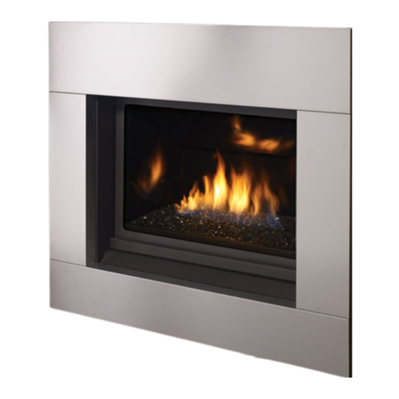
Regency Horizon ® HZ33CE
WARNING
FIRE OR EXPLOSION HAZARD
Failure to follow safety warnings exactly could result in serious
injury, death, or property damage.
- Do not store or use gasoline or other flammable vapors and liquids in the vicinity of this or any other
appliance.
- WHAT TO DO IF YOU SMELL GAS
•
Do not try to light any appliance.
• Do not touch any electrical switch: do not use any phone in your building.
Leave the building immediately.
• Immediately call your gas supplier from a neighbour's phone. Follow the gas supplier's
instructions.
• If you cannot reach you gas supplier, call the fire department.
- Installation and service must be performed by a qualified installer, service agency or the gas supplier.
Tested by:
FPI FIREPLACE PRODUCTS INTERNATIONAL LTD. 6988 Venture St., Delta, BC Canada, V4G 1H4
919-366b
Gas Fireplace
Installer: Please complete the details on the back cover
and leave this manual with the homeowner.
Homeowner: Please keep these instructions for future reference.
Owners &
Installation Manual
MODEL: H
33CE-NG10 Natural Gas
Z
H
Z
33CE-LP10 Propane
HZ33CE Video
www.regency-fire.com
04.27.17
Advertisement
Table of Contents

Related Manuals for Regency Fireplace Products Horizon HZ33CE-NG10


Summary of Contents for Regency Fireplace Products Horizon HZ33CE-NG10
- Page 1 Owners & Regency Horizon ® HZ33CE Installation Manual Gas Fireplace MODEL: H 33CE-NG10 Natural Gas 33CE-LP10 Propane HZ33CE Video www.regency-fire.com WARNING FIRE OR EXPLOSION HAZARD Failure to follow safety warnings exactly could result in serious injury, death, or property damage. - Do not store or use gasoline or other flammable vapors and liquids in the vicinity of this or any other appliance.
- Page 2 To the New Owner: Congratulations! You are the owner of a state-of-the-art Gas Fireplace by REGENCY . The HZ33CE has been designed to provide ® you with all the warmth and charm of a fire at the flick of a switch. The model HZ33CE has been approved by Warnock Hersey for both safety and efficiency.
- Page 3 MANUFACTURED MOBILE HOME REQUIREMENTS INFORMATION FOR MOBILE/MANUFACTURED HOMES AFTER FIRST SALE This Regency product has been tested and listed by Warnock Hersey as a Direct Vent Wall Furnace to the following standards: VENTED ® GAS FIREPLACE HEATERS ANSI Z21.88 - 2014 / CSA 2.33 - 2014 and GAS-FIRED APPLIANCES FOR USE AT HIGH ALTITUDES CAN / CGA 2.17-M91.
-
Page 4: Table Of Contents
table of contents SAFETY LABEL High Elevation ..............33 885 S.I.T. Valve Description .........33 Copy of Safety Decal .............5 Gas Pipe Pressure Testing ..........33 Conversion from NG to LP...........34 REQUIREMENTS Wiring Diagram ............35 MA Code - CO Detector ..........6 Aeration adjustment .............35 Optional Fan installation ..........36 DIMENSIONS Wiring diagram with optional fan .........39... -
Page 5: Copy Of Safety Decal
safety decal This is a copy of the label that accompanies each HZ33CE Direct Vent Gas Fireplace. We have printed a copy of the contents here for your review. NOTE: Regency units are constantly being improved. Check the label on the unit and if there is a difference, the label on the unit is the correct one. ®... -
Page 6: Requirements
requirements MA Code - CO Detector (for the State of Massachusetts only) 5.08: Modifications to NFPA-54, Chapter 10 (2) Revise 10.8.3 by adding the following additional requirements: (a) For all side wall horizontally vented gas fueled equipment installed in every dwelling, building or structure used in whole or in part for residential purposes, including those owned or operated by the Commonwealth and where the side wall exhaust vent termination is less than seven (7) feet above finished grade in the area of the venting, including but not limited to decks and porches, the following requirements shall be satisfied:... -
Page 7: Dimensions
dimensions UNIT DIMENSIONS 23" 584mm 2-1/2" 34-9/16" [64mm] [878mm] NAILING STRIP 3" (76mm) 26" 660mm 29-7/16" 747mm 4 SIDED FACEPLATE DIMENSIONS 42-5/16" (1074mm) 2" (51mm) Horizon ® HZ33CE-10 Gas Fireplace... -
Page 8: Important Message
installation IMPORTANT MESSAGE 4. This appliance must be connected to the speci- YOUNG CHILDREN SHOULD BE CARE- fied vent and termination cap to the outside of SAVE THESE the building envelope. Never vent to another FULLY SUPERVISED WHEN THEY ARE INSTRUCTIONS room or inside a building. -
Page 9: Installation Checklist
installation This includes: INSTALLATION CHECKLIST 1. Clocking the appliance to ensure the correct 4. This appliance is Listed for bedroom 1. Locate appliance: firing rate (rate noted on label), after burning installations when used with a listed Millivolt a) Room location (Refer to "Locating Your appliance for 15 minutes. -
Page 10: Clearances
installation CLEARANCES The clearances listed below are Minimum distances unless otherwise stated: A major cause of chimney related fires is failure to maintain required clearances (air space) to combustible materials. It is of the greatest importance that this fireplace and vent system be installed only in accordance with these instructions. Caution Requirements WARNING Fire hazard is an extreme risk... -
Page 11: Mantel Leg Clearances
installation MANTEL CLEARANCES Due to the extreme heat this fireplace emits, the Mantel Clearances mantel clearances are critical. Combustible mantel clearances from top of front facing are shown in the diagram on the right. Note: A non-combustible mantel may be 12"... -
Page 12: Framing & Finishing
installation FRAMING & FINISHING 1. There are 8 (eight) side nailing strips and one top nailing strip available on the unit. One set of four (4) are for a clean finish installation, the other set are for a tile finish installation as they are set back 1/2" (13mm). The top nailing strip is adjustable to 1/2" (13mm). Bend the required four (4) nailing strips to 90º. - Page 13 Discoloration is not the responsibility of Regency Fireplace Products. This is outwith the control of Regency Fireplace Products Ltd., therefore not covered under any part of the warranty policy.
-
Page 14: Clean Finish
installation CLEAN FINISH 6. If applying a non-combustible facing it may be installed over the metal surface (clean front) of the unit in the area shown below. WOOD STUD Combustible Material 1/2" DRYWALL Non-combustible Material (3-1/2" x 34-9/16") DO NOT EXTEND Supplied with Unit DRYWALL ONTO METAL Non-combustible... -
Page 15: Framing Dimensions
installation FRAMING DIMENSIONS Non-combustible Header 2X4 HEADER (steel stud on edge) DETAIL N SCALE 1 : 6 NOTE: If this is an outside corner, the minimum distance between the vent and the outside corner is 6" (15cm) with AstroCap termination cap or 12" Floor (30cm) with Rigid Vent termination cap. -
Page 16: Venting Introduction
installation VENTING INTRODUCTION The HZ33CE uses the "balanced flue" technology Co-Axial system. The inner liner vents products of combustion to the outside while the outer liner draws outside combustion air into the combustion chamber thereby eliminating the need to use heated room air for combustion and losing warm room air up the chimney. -
Page 17: Exterior Vent Termination Requirements
installation EXTERIOR VENT TERMINATION REQUIREMENTS Minimum Clearance Requirements Canada Clearance above grade, veranda, porch, deck, or balcony 12"(30cm) 12"(30cm) Clearance to window or door that may be opened 12"(30cm) 9" (23cm) Clearance to permanently closed window Vertical clearance to ventilated soffit located above the terminal within a horizontal distance of 2 feet (61cm) 18"(46cm) 18"(46cm) from the center line of the terminal (check with the local code) -
Page 18: Regency ® Direct Vent Flex System
installation REGENCY DIRECT VENT FLEX SYSTEM ® Horizontal Terminations Only This venting system, in combination with the HZ33CE-10 Direct Vent Gas Fireplace, have been tested and listed as a direct vent heater system by Warnock Hersey. The location of the termination cap must conform to the requirements in the "Exterior Vent Terminal Locations" Section . Regency Direct Vent Flex Termination Kit (Part # 946-513. -
Page 19: Rigid Pipe Venting Systems
installation RIGID PIPE VENTING SYSTEMS Horizontal or Vertical Terminations The minimum components required for a basic Vertical horizontal termination are: Terminal AstroCap Horizontal Termination Cap Storm Collar Elbow Vinyl Siding Rigid Pipe Adaptor Standoff (Optional) Wall Thimble Flashing Length of pipe to suit wall thickness (see chart) Horizontal For siding other than vinyl, furring strips may... -
Page 20: 4" X 6-5/8" Rigid Pipe Cross Reference Chart
installation 4" X 6-5/8" RIGID PIPE CROSS REFERENCE CHART 4” X 6- ” RIGID PIPE CROSS REFERENCE CHART Components from different Manufacturers may not be mixed. Not all rigid pipe components are available directly from Regency. Note: The listed manufacturers may have other lengths not shown on this chart, which would also be approved. Description Selkirk American Metal... - Page 21 installation Description Selkirk American Metal Security ICC Excel Olympia Simpson Metal-Fab™ Ventis DV* Direct Temp™ Products® Secure- Vent® Direct Direct Vent Pro ® Sure Seal Amerivent Direct Attic Insulation Shield 12” 46DVA-IS 4DAIS12 SV4RSA VDV-AIS04 N/A@ FPI Attic Insulation Shield 4DAIS12 TM-4AS - Cold Climates 36”...
-
Page 22: Rigid Pipe Venting Arrangements
installation RIGID PIPE VENTING ARRANGEMENTS Vertical Terminations (Propane & Natural Gas) elbow, with rigid pipe The shaded area in the diagram shows all allowable combinations of straight vertical and offset to vertical terminations, using one 90 vent systems for Propane and Natural Gas. •... -
Page 23: Vertical Termination With Co-Linear Flex System
installation VERTICAL TERMINATION WITH CO-LINEAR FLEX SYSTEM Masonry chimneys may take various contours which the flexible liner will accommodate. However, THE APPLIANCE MUST NOT BE keep the flexible liner as straight as possible, avoid unnecessary bending. CONNECTED TO A CHIMNEY FLUE SERVING A SEPARATE SOLID FUEL The Air Intake pipe must be attached to the inlet air collar of the termination cap. -
Page 24: Venting Arrangements - Vertical Terminations
installation VENTING ARRANGEMENTS - VERTICAL TERMINATIONS with Co-linear Flex System for both Residential & Manufactured Homes into Masonry Fireplaces Floor Floor Horizontal Distance (Feet) Horizontal Distance (Feet) Horizontal Distance (Feet) The shaded area in the diagrams show the allowable vertical terminations. 24 | ®... - Page 25 installation RIGID PIPE VENTING ARRANGEMENTS Horizontal Terminations REGENCY DIRECT VENT SYSTEM (FLEX) ® (Propane & Natural Gas) This diagram shows all allowable combinations of vertical runs with horizontal terminations, using one 45 and one 90 elbow (two 45 elbows equal one 90 elbow).
- Page 26 installation Horizontal Venting with Two (2. 90 Elbows Horizontal Venting with Three (3. 90 Elbows One 90 elbow = Two 45 elbows. One 90 elbow = Two 45 elbows. Option H + H1 With these options, maximum Option H + H1 + H2 With these options, total pipe length is 30 feet maximum total pipe...
- Page 27 installation Horizontal Venting with Three (3. 90 Elbows One 90 elbow = Two 45 elbows. Option V + V1 H + H1 With these options, maximum total pipe 2' Min. 1' Max. 3' Min. 4' Max. length is 30 feet with minimum of 12 feet 3' Min.
- Page 28 installation Vertical Venting with Three (3. 90 Elbows One 90 elbow = Two 45 elbows. Option H + H1 V + V1 With these options, max. total 1' Max. 1' Min. 3' Max. 3' Min. pipe length is 30 feet with min. 2' Max.
-
Page 29: Unit Installation With Horizontal Termination
installation UNIT INSTALLATION WITH HORIZONTAL TERMINATION Install the vent system according to the Riser Vent Diagram 2a b) Horizontal runs of vent must be supported Termination manufacturer's instructions included with the every three feet. Wall straps are available components. for this purpose. 1. -
Page 30: Unit Installation With Vertical Termination
installation 8. Slide the appliance and vent assembly 4. Assemble the desired lengths of pipe and towards the wall carefully inserting the elbows. Ensure that all pipes and elbow vent pipe into the vent cap assembly. It is connections are in the fully twist-locked important that the vent pipe extends into the position and sealed. -
Page 31: Vertical Termination - 4'' X 6-5/8'' Venting
installation VERTICAL TERMINATION VERTICAL TERMINATION 4" X 6-7/8" VENTING 4" X 6-7/8" VENTING - VERTICAL FLEX VENT KIT (946-755) 1. Maintain the 1-½” clearance (air space) to combustibles when passing 11. Secure inner fl ex pipe to pipe adaptor by using Mill-Pac over the adaptor. through ceilings, walls, fl oors, enclosures, attic rafters or other nearby Slide the inner pipe over adaptor and secure with 3 screws. combustibles. -
Page 32: Flex Vent Components
installation VERTICAL FLUE EXTENSION KIT (PART #946/756) VERTICAL FLUE EXTENSION KIT (PART # 946-756) 20 foot Flex pipe Extension (Used in conjunction with the 946-755 Vertical Flex kit and 948-367/P flex 4" (100mm) inner pipe to flex adaptor). CEILING FIRESTOP/FIRESTOP SPACER 20ft. -
Page 33: Pilot Adjustment
installation GAS PIPE PRESSURE PILOT ADJUSTMENT HZ33CE-NG10 System Data TESTING Periodically check the pilot flames. Correct flame pattern has two strong blue flames: Conversion Kit# 433-971 (NG to LP) The appliance must be isolated from the gas 1 flowing around the flame sensor and 1 supply piping system by closing its individual flowing across the burner (it does not have For 0 to 4500 feet altitude... -
Page 34: Conversion From Ng To Lp
installation HZ33CE CONVERSION KIT# 438-971 FROM NG TO LP Conversion from NG to LPG For HZ33CE using SIT 885 NOVA Gas Valve for HZ33CE using SIT 885 NOVA Gas Valve THIS CONVERSION MUST BE DONE BY A QUALIFIED GAS FITTER IF IN DOUBT DO NOT DO THIS CONVERSION !! 4. -
Page 35: Wiring Diagram
installation WIRING DIAGRAM This heater does not require a 120V A.C. supply for operation but it is highly recommended to install the supplied AC adaptor to eliminate the need for batteries. In case of a power failure, the burner switch and the optional remote control will continue to operate if batteries are installed in the receiver.. However, a 120V A.C. -
Page 36: Optional Fan Installation
HZ33CE installation OPTIONAL FAN INSTALLATION OPTIONAL FAN INSTALLATION 5. Slide the thermodisc/cover assembly on to the bracket clip on the Follow these instructions before the Initial installation into the framing. underside of the fi rebox. If installing the optional fan into an Existing installation see the instruc- tions on the following page. - Page 37 HZ33CE installation Follow these instructions for Existing Installations. 6. Manoeuvre the fan into the valve tray opening at the base of the fi rebox 120 Volt AC power is needed for the fan. The fan can be hard wired if desired.
- Page 38 installation HZ33CE 11. Plug in the fan power cord to the Fan Control Module into the outlet marked “Fan”. Plug the FCM-COM wire from the remote control wiring harness into the location on the Fan Control Module marked TO REMOVE THE FAN “COM”.
-
Page 39: Wiring Diagram With Optional Fan
installation WIRING DIAGRAM WITH OPTIONAL FAN Proflame System Configuration 886 GTMF Wire Diagram SureFire™ Switch Caution: Ensure that the wires do not touch any CAUTION: Label all wires prior to disconnection hot surfaces and are away from sharp edges. when servicing controls. Wiring errors can cause improper and dangerous operation. -
Page 40: Optional Wall Thermostat Installation
installation OPTIONAL WALL THERMOSTAT INSTALLATION 4) Connect the other thermostat lead to male connector disconnected A wall thermostat may be installed if desired. from Step1using a female spade connector - see picture below. Recommended: The Wall Thermostat should be mounted beside the Re- mote/Unit Receiver which comes standard with the appliance. -
Page 41: Optional Reflective Panel Installation
installation OPTIONAL REFLECTIVE PANEL INSTALLATION Before installation, panels must be handled and cleaned as per instructions noted below: Black Enamel Panels • Black Enamel panels must be inspected for scratches and dimples prior to installation. All claims to be recorded at this time. Claims for damage after installation will not receive consideration. -
Page 42: Glass Crystals And Optional Stones
installation GLASS CRYSTALS AND OPTIONAL STONES INSTALLATION ON BURNER AND FIREBOX FLOOR Spread the Glass Crystals or Stones evenly over the burner. Ensure the crystals (or stones) do not overlap too much as this will effect the flame pattern. IMPORTANT NOTE: Only the supplied approved Glass Crystals and Stones are to be used with these fireplaces. -
Page 43: Optional Log Set Installation
HZ33CE/HZ30E installation HZ33CE/HZ30E - LOG INSTALLATION OPTIONAL LOG SET INSTALLATION Read the instructions below carefully and refer to the images. If the logs are broken do not use the unit until they are replaced. Broken logs can interfere with pilot operation. Improper positioning of the logs and lava embers may create carbon build-up and can alter the unit's performance which is not covered under warranty. - Page 44 HZ33CE/HZ30E installation 9. Place Left Log (2 ) match pin landing on Log 2 with pin on Log 1, the bottom should rest on the glass as shown below. HZ33CE use bottom pin landing HZ33CE shown - Left Log (2) positioned to rest on Log 1 and glass crystals.
-
Page 45: Glass Door And Mesh Barrier Installation
installation GLASS DOOR AND SAFETY SCREEN INSTALLATION STANDARD FLUSH DOOR Use the hook to pull the spring out until you can put the hook into the slot on the bottom door bracket. Repeat for 2nd spring. See Diagram 4. Both the standard flush door comes with a black frame. Install the glass door by hooking the top door flange onto the top of the unit and swing the door towards the unit, Diagram 2. -
Page 46: Optional 4-Sided Faceplate Installation
installation OPTIONAL 4-SIDED FACEPLATE INSTALLATION If installing the optional faceplate ensure the combustible and non combustible material around the unit are installed 3. Line up the middle rib on backside of faceplate with middle indent on bracket. flush with the unit. (See Diagram 1 below). This will centre the faceplate and allow 1/16" adjustment from side to side. The faceplate cannot be installed if materials are not flush. Combustible Material Non-combustible Material (3-1/2"... -
Page 47: Operating Instructions Operating Instructions
operating instructions OPERATING NORMAL OPERATING INSTRUCTIONS SOUNDS OF GAS APPLIANCES 1. Read and understand these instructions before operating this appliance. It is possible that you will hear some sounds from your gas appliance. This is perfectly normal due to 2. Check to see that all wiring is correct and the fact that there are various gauges and types enclosed to prevent possible shock. -
Page 48: Lighting Procedure
operating instructions LIGHTING PROCEDURE IMPORTANT: The remote control system supplied with this appliance has several options for starting/operating the appliance using the power button 3. After approximately 4 seconds the spark ignition system will spark for 60 and ON/OFF key on the hand held transmitter. seconds to light the main burner. -
Page 49: Copy Of Lighting Plate Instructions
operating instructions COPY OF LIGHTING PLATE INSTRUCTIONS FOR YOUR SAFETY READ BEFORE LIGHTING This appliance must be installed in accordance with local codes, if any; if none, follow the National Fuel Gas Code, ANSI Z223.1/NFPA 54, or Natural Gas and Propane Installation Codes, CSA B149.1. WARNING: If you do not follow these instructions exactly, a fire or explosion may result causing property damage, personal injury or loss of life. -
Page 50: Maintenance Maintenance Instructions
maintenance GLASS GASKET GENERAL VENT MAINTENANCE MAINTENANCE INSTRUCTIONS If the glass gasket requires replacement use a tadpole glass gasket (Part # 936-155.. Conduct an inspection of the venting system 1. Always turn off the gas valve before cleaning. semi-annually. Recommended areas to inspect For relighting, refer to lighting instructions. - Page 51 maintenance VALVE TRAY REPLACEMENT Removing Valve 8. Remove the 12 screws securing the valve tray assembly in place (Diagram 4. and then lift the entire assembly out (Diagram 5.. 1. Shut off the gas supply. NOTE: Parts have been hidden to shown screw locations. 2.
-
Page 52: Parts List
parts list MAIN ASSEMBLY Part # Description Part # Description 438-917 Fan Assembly 910-142 Thermodisc • 910-331/P Fan Motor Only 904-434 Orifice #47 NG • 911-030 Fan Control Module • 904-241 Orifice #56 LP 438-529 Mesh Guard 911-084 885 Proflame Valve NG 433-538 Door Assembly •... -
Page 53: Accessories
parts list ACCESSORIES Part # Description Parts Descritpion 434-908 Enamel Panel Set 1 Pound bag of glass crystals 437-954 Faceplate Black 946-675 Black Reflective Crystals 946-676 Copper Crystals 437-957 Faceplate Brushed Stainless 946-677 Starfire Crystals 437-952 Faceplate Sunset Bronze 437-971 Verona Glass Surround Pure Black 5 Pound bag of glass crystals 437-975... -
Page 54: Warranty
warranty Limited Lifetime Warranty FPI Fireplace Products International Ltd. (for Canadian customers) and Fireplace Products U.S., Inc. (for U.S. customers) (collectively referred to herein as “FPI”) extends this Limited Lifetime Warranty to the original purchaser of this appliance provided the product remains in the original place of installation. The items covered by this limited warranty and the period of such coverage is set forth in the table below. - Page 55 warranty At all times FPI reserves the right to inspect reported complaints on location in the field claimed to be defective prior to processing or authorizing of any claim. Failure to allow this upon request will void the warranty. All warranty claims must be submitted by the dealer servicing the claim, including a copy of the Bill of Sale (proof of purchase by you).
- Page 56 warranty Limitations of Liability: The original purchaser’s exclusive remedy under this warranty, and FPI’s sole obligation under this warranty, express or implied, in contract or in tort, shall be limited to replacement, repair, or refund, as outlined above. IN NO EVENT WILL FPI BE LIABLE UNDER THIS WARRANTY FOR ANY INCIDENTAL OR CONSEQUENTIAL COMMERCIAL DAMAGES OR DAMAGES TO PROPERTY.
- Page 57 warranty Product Registration and Customer Support: Thank you for choosing a Regency Fireplace. Regency strives to be a world leader in the design, manufacture, and marketing of hearth products. To provide the best support for your product, we request that you complete a product registration form found on our Web Site under Customer Care within ninety (90) days of purchase.
- Page 60 Installer: Please complete the following information Dealer Name & Address: ______________________________________________ ___________________________________________________________________ HZ33CE Video Installer: ___________________________________________________________ Phone #: ___________________________________________________________ Date Installed: ______________________________________________________ Serial No.: __________________________________________________________ Regency Horizon and SureFire are trademarks of FPI Fireplace Products International Ltd. Printed in Canada ©...