Table of Contents
Advertisement
Quick Links
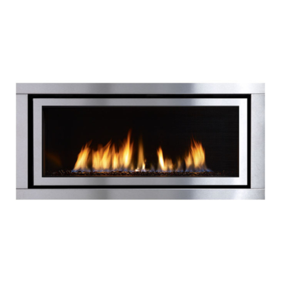
Regency Horizon
WARNING:
If the information in these instructions are not followed exactly,
a fi re or explosion may result causing property damage,
personal injury or loss of life.
FOR YOUR SAFETY
Do not store or use gasoline or other fl ammable vapors and
liquids in the vicinity of this or any other appliance.
Installation and service must be performed by a qualifi ed
installer, service agency or the gas supplier.
Tested by:
918-947a
FPI FIREPLACE PRODUCTS INTERNATIONAL LTD. 6988 Venture St., Delta, BC Canada, V4G 1H4
Gas Fireplace
Installer: Please complete the details on the back cover
and leave this manual with the homeowner.
Homeowner: Please keep these instructions for future reference.
HZ54EPV
™
Owners &
Installation Manual
MODELS: HZ54EPV-NG Natural Gas
www.regency-fi re.com
FOR YOUR SAFETY
What to do if you smell gas:
Do not try to light any appliance
Do not touch any electrical switch:
do not use any phone in your
building.
Immediately call your gas supplier
from a neighbour's phone. Follow
the gas supplier's instructions.
If you
cannot reach your gas
supplier, call the fi re department.
HZ54EPV-LP Propane
06/29/11
Advertisement
Table of Contents

Related Manuals for Regency Fireplace Products HZ54EPV-NG


Summary of Contents for Regency Fireplace Products HZ54EPV-NG
- Page 1 Owners & Regency Horizon HZ54EPV ™ Installation Manual Gas Fireplace MODELS: HZ54EPV-NG Natural Gas HZ54EPV-LP Propane www.regency-fi re.com WARNING: FOR YOUR SAFETY If the information in these instructions are not followed exactly, What to do if you smell gas: Do not try to light any appliance a fi...
- Page 2 To the New Owner: Congratulations! ® You are the owner of a state-of-the-art Gas Fireplace by REGENCY . The HZ54EPV has been designed to provide you with all the warmth and charm of a wood fi replace at the fl ick of a switch. The model HZ54EPV has been approved by Warnock Hersey/Intertek for both safety and effi...
- Page 3 MANUFACTURED MOBILE HOME REQUIREMENTS INFORMATION FOR MOBILE/MANUFACTURED HOMES AFTER FIRST SALE ® This Regency product has been tested and listed by Warnock Hersey/Intertek as a Direct Vent Wall Furnace to the following standards: VENTED GAS FIREPLACE HEATERS ANSI Z21.88a-2007 / CSA 2.33a-2007 and GAS-FIRED APPLIANCES FOR USE AT HIGH ALTITUDES CAN / CGA 2.17-M91.
-
Page 4: Table Of Contents
TABLE OF CONTENTS SAFETY LABEL Battery installation ............36 GT remote Installation ..........36 GTM remote installation ..........37 Copy of Safety Decal .............5 GTMF remote installation ..........38 OptionaL Refl ective Panel Installation ......40 REQUIREMENTS Glass Crystals or optional ceramic stones ....41 Installation On Burner ..........41 MA Code - CO Detector..........6 Glass Crystals or optional pebbles ......42 (for the State of Massachusetts only) ......6... -
Page 5: Safety Label
SAFETY LABEL This is a copy of the label that accompanies each HZ54EPV-NG and HZ54EPV-LP Direct Vent Gas Fireplace. We have printed a copy of the contents here for your review. ® NOTE: Regency units are constantly being improved. Check the label on the unit and if there is a difference, the label on the unit is the correct one. -
Page 6: Requirements
REQUIREMENTS MA Code - CO Detector (for the State of Massachusetts only) 5.08: Modifications to NFPA-54, Chapter 10 (2) Revise 10.8.3 by adding the following additional requirements: (a) For all side wall horizontally vented gas fueled equipment installed in every dwelling, building or structure used in whole or in part for residential purposes, including those owned or operated by the Commonwealth and where the side wall exhaust vent termination is less than seven (7) feet above finished grade in the area of the venting, including but not limited to decks and porches, the following requirements shall be satisfied:... -
Page 7: Dimensions
DIMENSIONS UNIT DIMENSIONS 52-5/8” (1337mm) 59” (1499mm) 19-3/4” (502mm) 10-5/8” (270mm) 1-1/2” 20-1/2” (521mm) (38mm) 48-1/2” (1232mm) FACEPLATE & DOOR FRAME OVERLAY DIMENSIONS Regency Horizon HZ54EPV Gas Fireplace... -
Page 8: Installation
INSTALLATION IMPORTANT MESSAGE 10) Be aware of electrical wiring locations in walls YOUNG CHILDREN SHOULD BE CARE- and ceilings when cutting holes for termination. SAVE THESE FULLY SUPERVISED WHEN THEY ARE 11) Under no circumstances should this appliance IN THE SAME AREA AS THE APPLI- INSTRUCTIONS be modifi... -
Page 9: Installation Checklist
INSTALLATION This includes: INSTALLATION 4) This appliance is Listed for bedroom CHECKLIST 1) Clocking the appliance to ensure the correct installations using the standard Remote fi ring rate (rate noted on label 41,500 Btu/h (millivolt thermostat system). Some areas may (NG), after burning appliance for 15 minutes. -
Page 10: Clearances
INSTALLATION CLEARANCES The clearances listed below are Minimum distances unless otherwise stated: A major cause of chimney related fi res is failure to maintain required clearances (air space) to combustible materials. It is of the greatest importance that this fi replace and vent system be installed only in accordance with these instructions. WARNING Caution Requirements Fire hazard is an extreme risk if these clearances (air space) to combustible materials... -
Page 11: Non-Combustible Facing Board
INSTALLATION NON-COMBUSTIBLE FACING BOARD All four pieces (top, 2 sides, bottom) are now supplied to meet the non combustible requirements. Previously only the top was supplied. Metal Stud (header) If fi nishing the wall above the unit with paint - 61-1/2"... -
Page 12: Mantel Clearances
INSTALLATION MANTEL CLEARANCES Due to the extreme heat this fi replace emits, the mantel clearances are critical. Combustible mantel clearances from top of front facing are shown in the diagram on the right. Combustible Material Note: A non-combustible mantel may be installed at a lower height if the framing 13"... -
Page 13: Framing & Finishing
INSTALLATION FRAMING & FINISHING 1) Frame in the enclosure for the unit with framing material. 6) Determine the total thickness of facing material (eg. hardiboard + ceramic tile) to ensure the fi nished surface is fl ush with the front edge of the IMPORTANT: Header must be metal stud. -
Page 14: Framing Dimensions
INSTALLATION FRAMING DIMENSIONS Framing Description HZ54EPV Dimensions Framing Height 46-5/8” (1184mm) Framing Width 60” (1524mm) B1 (see next page) Framing Width (negative vent run) 70" (1778mm) B2 (see next page) Framing Width (negative vent run) 80" (2032mm) 22” (559mm) Framing Depth 31”... -
Page 15: Framing With A Negative Vent Run
INSTALLATION FRAMING WITH A NEGATIVE VENT RUN Parts required rigid pipe 90° elbow 8" slip 18" length 90° elbow adaptor rigid pipe adaptor 18" pipe length 8" slip 90° elbows Note: Framing height and depth remain the same as previous page. 70”... -
Page 16: Unit Assembly Prior To Installation
INSTALLATION UNIT ASSEMBLY NAILING STRIPS PRIOR TO The nailing strips come attached to the unit. There is 1 plate on each side,1 on the top, and one on the bottom that can be folded out as required. The INSTALLATION top and side nailing strips are secured to the framing. The bottom nailing strip is secured to the unfi... -
Page 17: Vent Restrictor Position
INSTALLATION VENT RESTRICTOR POSITION Vent restriction is required for certain venting installations, see the diagrams in the "Venting Arrangements" section to determine if they are required for your installation. The Vent Restrictor plate is located on the inside top of the fi rebox. To set the vent restriction as indicated in the venting arrangements diagrams, refer to the following instructions;... -
Page 18: Gas Power Vent Installation Rigid Pipe Only
INSTALLATION GAS POWER VENT INSTALLATION RIGID PIPE ONLY The Power Vent System is a Direct Vent Terminal designed to allow installation of gas appliances where typical vent confi gurations cannot be achieved. These installation instructions must be used in conjunction with the appliance and appropriate Power Vent components installation instructions. 120 Volt power supply is required to operate this system (see Electrical Installation section in this manual). -
Page 19: 5" X 8" Rigid Pipe Cross Reference Chart
INSTALLATION 5” X 8” RIGID PIPE CROSS REFERENCE CHART Components from different Manufacturers may not be mixed. Not All Rigid Pipe components are available directly from FPI. Description Simpson Metal-Fab™ ® Direct Vent Pro Sure Seal 6” Pipe Length-Galvanized 58DVA-06 6”... - Page 20 INSTALLATION Description Simpson Metal-Fab™ ® Direct Vent Pro Sure Seal Attic Insulation Shield 12” 58DVA-IS N/A from FPI Basic Horizontal Termination Kit (A) Horizontal Termination Kit (B) 58DVA-KHA Vertical Termination Kit 58DVA-VHA High Wind Vertical Cap 58DVA-VCH High Wind Horizontal Cap Horizontal Square Termination Cap 5DHT Vertical Termination Cap...
-
Page 21: Venting Arrangements For Horizontal Terminations
INSTALLATION VENTING ARRANGEMENTS FOR HORIZONTAL TERMINATIONS (RIGID PIPE 5" X 8" - MUST USE REDUCER #946-606 & RIGID PIPE ADAPTOR # 770-994) The gas power vent systems is designed to allow the installation of a gas appliance when typical vent confi gurations (shown in this manual) are not possible. -
Page 22: Exterior Vent Termination Requirements
INSTALLATION EXTERIOR VENT TERMINATION REQUIREMENTS Minimum Clearance Requirements Canada Clearance above grade, veranda, porch, deck, or balcony 12"(30cm) 12"(30cm) Clearance to window or door that may be opened 12"(30cm) 9" (23cm) Clearance to permanently closed window Vertical clearance to ventilated soffi t located above the terminal within a horizontal distance of 2 feet (61cm) 12"(30cm) 12"(30cm) from the center line of the terminal (check with the local code) - Page 23 INSTALLATION POWER VENT TERMINAL INSTALLATION WARNING: 4) Remove the plate from the bottom right corner of the frame by removing 2 screws from the inside of the frame. ELECTRICAL CONNECTIONS SHOULD ONLY BE CARRIED OUT BY A QUALIFIED AND LICENSED ELECTRICIAN Note: Optional 5 wire BX cable comes in 20' or 60' lengths as required.
- Page 24 INSTALLATION 8 ) Reattach the plate to the inside of the Power Vent outer frame with 2 12) Tighten bolt to secure ground wire. screws from step 3. 9) Feed the BX cable through the opening in the power vent terminal - located in the lower left corner as shown below.
-
Page 25: Clearances To The Power
INSTALLATION PIPE CONNECTION FROM TERMINAL 16) Install cap over terminal with 4 screws. TO UNIT Note: Cap may be painted to match building color. The rigid pipe and rigid pipe adaptor starting from the installed unit must be installed prior to proceeding. Install 8"... -
Page 26: Electrical Installation
INSTALLATION ELECTRICAL INSTALLATION WARNING 5) Loosen 2 screws - one on either side of the electrical box. Slide box up and push box back to release. THIS INSTALLATION SHOULD ONLY BE CARRIED OUT BY A QUALIFIED AND LICENSED ELECTRICIAN Electrical Note: For ease of installation, the electrical installation must be completed prior to adding any fi... - Page 27 INSTALLATION 12) Connect all like colored wires - blue to blue, red to red, white to white and black to black. Finish wire ends with marettes as shown below. 9) Feed wires from the BX cable through into the box. 13) Install the cover on the electrical junction box-secure with 2 screws.
-
Page 28: Power Vent Wiring Diagram
INSTALLATION POWER VENT WIRING DIAGRAM WARNING Electrical Grounding Instructions This appliance is equipped with a three-prong (grounding) plug for your protection against shock hazard and should be plugged directly into a properly grounded three-prong receptacle. Do not cut or remove the grounding prong from this plug. WHITE WHITE BLUE... -
Page 29: Aeration Adjustment
INSTALLATION AERATION ADJUSTMENT CAUTION: Carbon will be produced if air shutter The burner aeration is factory set but may need Minimum Air Shutter Opening: is tightly closed. adjusting due to either the local gas supply or altitude. Open the air shutter for a blue fl ame or 1/2"... -
Page 30: High Elevation
INSTALLATION 1) Make sure the valve is in the "OFF" position. HZ54EPV-NG SYSTEM DATA 2) Loosen the "IN" and/or "OUT" pressure tap(s), Min. Supply Pressure 5" WC (1.25 kpa) turning counterclockwise with a Low Setting Man. 1.6" WC (0.40kpa) 1/8" wide fl at screwdriver. -
Page 31: Valve Cover Removal
INSTALLATION VALVE COVER REMOVAL The valve cover will need to be removed to access the valve tray (see valve 4) Lift the cover up off the screws and out of the unit. tray replacement) and also to access the DBFC (see Battery + ON/OFF switch installation). -
Page 32: Optional Fan Wiring Diagram
INSTALLATION OPTIONAL FAN WIRING DIAGRAM WITHOUT PROFLAME GTMF SYSTEM Green (Ground) 120 VAC Lockwasher White (Neutral) Ground for 60HZ Black (Live) Star washer (*by others) mobile home #8 Ground Lug (for mobile home) (*by others) Rotary Speed Control White Black (*Supplied by others ground wire... -
Page 33: Optional Remote Control
INSTALLATION Optional RECEIVER WALL SWITCH (Included with Unit) REMOTE CONTROL 1) Run the supplied 10' of the wire harness through the right or left side gas inlet opening- connect the ON/OFF wire harness. Be careful not to damage ® Use the Regency Remote Control approved for this unit. -
Page 34: Wall Mount Receiver Installation
INSTALLATION WALL MOUNT RECEIVER INSTALLATION REQUIRED FOR ALL INSTALLATIONS - INCLUDING PROFLAME REMOTE CONTROLS MPORTANT INSTALLATION NOTE: The Receiver must be placed inside the supplied (Low Voltage) junction type wall box and installed into the wall only. DO NOT INSTALL WITHIN THE CONFINES OF THE FIREPLACE. Wall Mounting 1. - Page 35 INSTALLATION 584 Proflame GT Series Feature Sheet Indicates Included Feature Note 1 ~ Profl ame Flame Modulator for GTM & GTMF Remote Controls are sold seperately. Choice of NG or LP fl ame modulator (to match unit fuel type). See Regency Retail Price pages for complete details Note 2 ~ FPI Profl...
-
Page 36: Battery Installation
INSTALLATION BATTERY INSTALLATION 1) Install 4 - AA batteries into the receiver, ensure correct polarity. GT REMOTE INSTALLATION 1. GT remote installation - see Profl ame remote instructions for coding remote to receiver as well as operating instructions. J-Box Receiver Slider Switch Wall Plate 12 pin connector - located... -
Page 37: Gtm Remote Installation
INSTALLATION GTM REMOTE INSTALLATION DFBC = digital fi replace burner control 5) Remove the module tray on the right side of the unit to access the DFBC 1) Remove the faceplate and glass door to access to Receiver. 6) Plug receiver wires into the back of the receiver and bundle wires with the wire clip as shown below. -
Page 38: Gtmf Remote Installation
INSTALLATION GTMF REMOTE INSTALLATION DFBC = digital fi replace burner control 6) Remove the module tray on the right side of the unit to access the DFBC Remove the faceplate and glass door to access to DFBC & battery pack tray. Lift DFBC and battery pack up and out. - Page 39 INSTALLATION 10) From the wire harness, plug the FCM wire into the fan control module. FCM wire Fan Control Module 11) Install the fan control module onto t the fl oor of the unit. Place it to the right of the receiver. 12) Plug fan control module into receptacle located on the left hand side of the unit.
-
Page 40: Optional Refl Ective Panel Installation
INSTALLATION OPTIONAL REFLECTIVE PANEL INSTALLATION Before installation, panels must be handled and cleaned as per instructions noted below: Stainless Steel Panels Black Enamel Panels • • Stainless panels must be inspected for scratches and dimples prior Black Enamel panels must be inspected for scratches and dimples to installation. -
Page 41: Glass Crystals Or Optional Ceramic Stones
INSTALLATION GLASS CRYSTALS OR OPTIONAL CERAMIC STONES INSTALLATION ON BURNER Evenly spread the supplied Glass Crystals or optional Ceramic Spa or Garden Stones over the burner. Ensure the crystals (or stones) do not overlap too much as this will effect the fl ame pattern. IMPORTANT NOTE: Only the supplied approved Cobalt Glass, Ceramic Spa Stones or Garden Stones are to be used with these fi... -
Page 42: Glass Crystals Or Optional Pebbles
INSTALLATION GLASS CRYSTALS OR OPTIONAL PEBBLES INSTALLATION ON FIREBOX BASE Firebox Packages Unit Glass Crystals Pebbles HZ54E / HZ54EPV 6 Bags 2 packages (6 x bags pebbles) HZ42 / HZ42E 5 Bags 2 packages (6 x bags pebbles) HZ42 ST / HZ42STE 5 Bags 2 package (6 x bags pebbles) HZO42 / HZO42 (AUS) 3 Bags... -
Page 43: Optional Log Set Installation
INSTALLATION OPTIONAL LOG SET INSTALLATION Installation of Refl ective Panels must be completed before installing the log set. Read the instructions below carefully and refer to the images. If the logs are broken do not use the unit until they are replaced. Broken logs can interfere with pilot operation. - Page 44 INSTALLATION Diagram 5 Pin clips installed - dots indicate dimple locations. *Actual dimples/pin clips are black - not white as shown 4) Install the glass crystals (see glass crystal installation section in this manual). Diagram 6 5) Place platinum embers on glass crystals as shown in diagram 7. Diagram 7 6) If installing optional pebbles - install pebbles before log installation.
- Page 45 INSTALLATION 7) Place logs A + B on the burner, rest logs on the pin clips, as shown in diagram 9. Note: Logs should be oriented exactly as shown in diagram 9. Diagram 9 8) Place logs C + D on logs A + B, as shown in diagram 10. Note: Logs should be oriented exactly as shown in diagram 10.
-
Page 46: Faceplate & Door Frame Overlay Installation
INSTALLATION FACEPLATE & DOOR FRAME OVERLAY INSTALLATION 3) Secure the left side mounting bracket to the backside of the faceplate 1) Install the door frame overlay by hooking the top fl ange over top of as shown below. Use 3 screws supplied to secure the mounting the glass door, push in the bottom of the door frame overlay to secure bracket in place. - Page 47 INSTALLATION 4) Install the faceplate to the unit by hooking the left and right side IMPORTANT NOTE mounting brackets into the mounting slots at the side of the fi rebox as shown below. It is recommended that you use the fi rst mounting To ensure the gap between the door frame and the faceplate slot (the one closest to the door frame overlay) out of the 5 so that are equal from side to side you may need to slide the faceplate...
-
Page 48: Optional Fan Installation
INSTALLATION OPTIONAL FAN INSTALLATION 5) Remove the glass door. Important: 120 Volt AC power is needed for the fan switch and blower. The receptacle box will be installed on the left hand side of the unit a) Remove cover plates from over each screw by pulling away from and must be wired by a qualifi... - Page 49 INSTALLATION 11) Manoeuvre the fan into position on the fl oor of the unit. Tilt the fan 6) Loosen 6 screws that secure the burner extenders. on burner tray, to get through the fan access panel and into position. located behind the burner on either side of the pilot assembly. 7) Lift out the 2 burner tray extenders.
- Page 50 INSTALLATION 15) Reverse Steps 8 through 5. 19) Attach the receiver to the unit with the velcro strip. Place the receiver in front of the ground lug on the left side of the unit - inside the bottom 16) Install the fan air defl ector - it hooks to 2 brackets on to the bottom lip of frame of the unit - follow steps 15-19 to complete installation.
-
Page 51: Operating Instructions
OPERATING INSTRUCTIONS INSTALLATION OPERATING LIGHTING NORMAL OPERATING INSTRUCTIONS PROCEDURE SOUNDS OF GAS APPLIANCES 1) Turn on the wall switch or press and release on 1) Read and understand these instructions before ON/OFF button once on the remote control. operating this appliance. It is possible that you will hear some sounds from your gas appliance. -
Page 52: Copy Of Lighting Plate Instructions
OPERATING INSTRUCTIONS COPY OF LIGHTING PLATE INSTRUCTIONS FOR YOUR SAFETY READ BEFORE LIGHTING This appliance must be installed in accordance with local codes, if any; if none, follow the National Fuel Gas Code, ANSI Z223.1/NFPA 54, or Natural Gas and Propane Installation Codes, CSA B149.1. WARNING: If you do not follow these instructions exactly, a fire or explosion may result causing property damage, personal injury or loss of life. -
Page 53: Maintenance Instructions
MAINTENANCE MAINTENANCE GLASS DOOR GENERAL VENT INSTRUCTIONS MAINTENANCE ® Your Regency fi replace is supplied with high temperature 5mm-Ceramic glass. If your glass Conduct an inspection of the venting system semi- 1) Always turn off the gas valve before cleaning. requires cleaning, we recommend using an annually. -
Page 54: Glass Door Removal
MAINTENANCE GLASS DOOR REMOVAL 1) Turn the unit off and allow it to cool down to room temperature. 5) Remove the glass door. 2) Turn off the gas supply to the unit. a) Remove the 3 screws shown below at the bottom of the glass door 3) Remove the faceplate by lifting it up off the hinges on the sides of the fi... -
Page 55: Valve Tray Replacement
MAINTENANCE VALVE TRAY REPLACEMENT 5) Remove the glass door. 1) Turn the unit off and allow it to cool down to room temperature. a) Remove cover plates from over each screw by pulling away from 2 2) Turn off the gas supply to the unit. magnets each as shown below. - Page 56 MAINTENANCE 1) Loosen 6 screws that secure the burner extenders. on burner tray, 7) Disconnect the green and orange wires from the valve. located behind the burner on either side of the pilot assembly. 2) Lift out the 2 burner tray extenders. Burner tray extenders Green Wire Blue Wire...
-
Page 57: Parts List
PARTS LIST MAIN ASSEMBLY Part # Description Part # Description 1) 476-151 Bottom Cover (False Tray) NG 7) 476-101 Burner Extenders (LP unit only) 476-152 Bottom Cover (False Tray) LP 476-042f LH / RH Nailing Strips 2) 476-525 Burner Assembly -NG 476-530 Burner Assembly-LP 8) 476-915... -
Page 58: Accessories
PARTS LIST ACCESSORIES Part # Description 30) 476-907 Refl ective Stainless Steel Panels 476-908 Black Enamel Inner Panels 31) 476-924 Faceplate & Door Frame Overlay - Black 476-927 Faceplate & Door Frame Overlay - Stainless Steel 476-926 Faceplate & Door Frame Overlay - Sunset Bronze 946-671 Cobalt Blue Glass Crystals 946-672... -
Page 59: Warranty
WARRANTY ® Regency Fireplace Products are designed with reliability and simplicity in mind. In addition, our internal Quality Assurance Team carefully inspects each unit thoroughly before it leaves our facility. Fireplace Products is pleased to extend this limited lifetime warranty to the original purchaser of a Regency ®... - Page 60 ® Register your Regency warranty online www.regency-fi re.com Reasons to register your product online today! • View and modify a list of all your registered products. • Request automatic email notifi cation of new product updates. • Stay informed about the current promotions, events, and special offers on related products.