Table of Contents
Advertisement
Quick Links
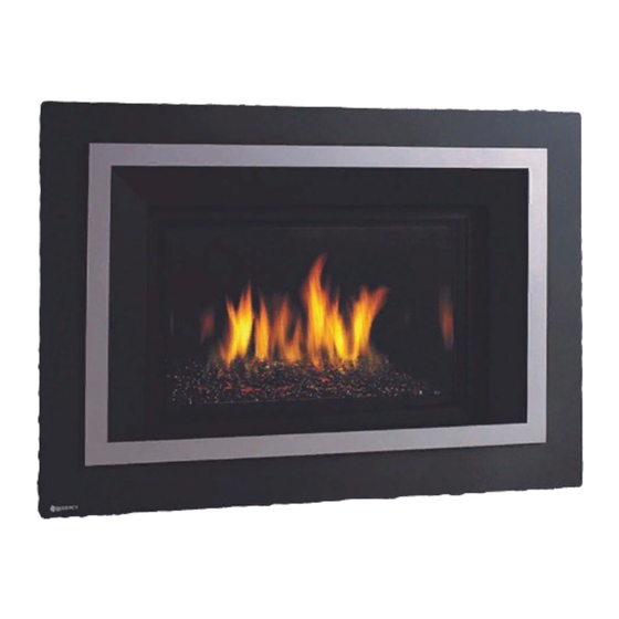
Liberty ® LRI4E / Regency Horizon ® HRI4E
MODELS: LRI4E-NG Natural Gas
HRI4E-NG Natural Gas
WARNING
FIRE OR EXPLOSION HAZARD
Failure to follow safety warnings exactly could result in serious
injury, death, or property damage.
- Do not store or use gasoline or other lammable vapors and liquids in the vicinity of this or any other
appliance.
- WHAT TO DO IF YOU SMELL GAS
•
Do not try to light any appliance.
• Do not touch any electrical switch: do not use any phone in your building.
Leave the building immediately.
• Immediately call your gas supplier from a neighbour's phone. Follow the gas supplier's
instructions.
• If you cannot reach you gas supplier, call the ire department.
- Installation and service must be performed by a qualiied installer, service agency or the gas supplier.
Tested by:
919-380c
FPI FIREPLACE PRODUCTS INTERNATIONAL LTD. 6988 Venture St., Delta, BC Canada, V4G 1H4
Gas Insert
LRI4E-LP Propane
HRI4E-LP Propane
Installer: Please complete the details on the back cover
and leave this manual with the homeowner.
Homeowner: Please keep these instructions for future reference.
Owners &
Installation Manual
®
Liberty
LRI4E
®
Horizon
HRI4E
www.regency-ire.com
08.05.16
Advertisement
Table of Contents

Related Manuals for Regency Fireplace Products Liberty LRI4E-NG


Summary of Contents for Regency Fireplace Products Liberty LRI4E-NG
- Page 1 Liberty ® LRI4E / Regency Horizon ® HRI4E Owners & Installation Manual Gas Insert ® Liberty LRI4E ® Horizon HRI4E www.regency-ire.com MODELS: LRI4E-NG Natural Gas LRI4E-LP Propane HRI4E-NG Natural Gas HRI4E-LP Propane WARNING FIRE OR EXPLOSION HAZARD Failure to follow safety warnings exactly could result in serious injury, death, or property damage.
- Page 2 TO THE NEW OWNER Congratulations! You are the owner of a state-of-the-art Gas Insert by Regency. The Regency Gas Insert Series of hand crafted appliances has been designed to provide you with all the warmth and charm of a ireplace, at the lick of a switch. The models LRI4E / HRI4E of this series have been approved by Warnock Hersey/Intertek for both safety and eficiency.
-
Page 3: Table Of Contents
table of contents Unit dimensions with vignette faceplate ......4 Heat exchange return ..........28 Unit dimensions with low proile faceplate .....5 Brick panel installation ..........29 Unit dimensions with 4 sided vignette faceplate ....6 Enamel panel installation..........30 Copy of Safety Label .............7 Glass door removal / installation .........31 MA Code - CO Detector..........8 Vignette faceplate with Safety screen installation ..32... -
Page 4: Unit Dimensions With Vignette Faceplate
dimensions UNIT DIMENSIONS WITH VIGNETTE FACEPLATE (762mm) 21-11/16" (550mm) 41-5/8" (1056mm) 14-7/16" (366mm) 35-1/8" (891mm) -3/16 " (457mm) LRI4E / HRI4E Direct Vent Gas Insert... -
Page 5: Unit Dimensions With Low Proile Faceplate
dimensions UNIT DIMENSIONS WITH LOW PROFILE FACEPLATE LRI4E / HRI4E Direct Vent Gas Insert... -
Page 6: Unit Dimensions With 4 Sided Vignette Faceplate
dimensions UNIT DIMENSIONS WITH 4 SIDED VIGNETTE FACEPLATE LRI4E / HRI4E Direct Vent Gas Insert... -
Page 7: Copy Of Safety Label
Max. Alcove Depth/Prof. max. alcôve Prof. max. manteau 12" (305mm) Regency Fireplace Products MADE IN CANADA /FABRIQU AU CANADA É Delta BC, CANADA This appliance must be installed in accordance with local codes, if any; if none, follow the National Fuel Gas Code, ANSI Z223.1, or Natural Gas and Propane Installation Code, CSA B149.1. -
Page 8: Ma Code - Co Detector
requirements MA Code - CO Detector (for the State of Massachusetts only) 5.08: Modifications to NFPA-54, Chapter 10 (2) Revise 10.8.3 by adding the following additional requirements: (a) For all side wall horizontally vented gas fueled equipment installed in every dwelling, building or structure used in whole or in part for residential purposes, including those owned or operated by the Commonwealth and where the side wall exhaust vent termination is less than seven (7) feet above finished grade in the area of the venting, including but not limited to decks and porches, the following requirements shall be satisfied:... -
Page 9: Important Message
installation IMPORTANT MESSAGE IMPORTANT MESSAGE YOUNG CHILDREN SHOULD BE CARE- SAVE THESE SAVE THESE FULLY SUPERVISED WHEN THEY ARE INSTRUCTIONS IN THE SAME AREA AS THE APPLI- INSTRUCTIONS ANCE. TODDLERS, YOUNG CHILDREN The Regency Gas Insert must be installed in AND OTHERS MAY BE SUSCEPTIBLE The LRI4E / HRI4E Gas Inserts must be installed in accordance with these instructions. -
Page 10: Gas Pressure Testing
installation General Safety Information GAS PRESSURE FACTORY-BUILT (METAL) WOOD- BURNING FIREPLACE TESTING 1) The appliance installation must conform with REQUIREMENTS local codes or in the absence of local codes, with CAN/CGA B149 (in Canada) or the National The appliance must be isolated from the gas sup- Fuel Gas Code ANSI Z223.1 in the U.S.A. -
Page 11: Installation Checklist
installation INSTALLATION MATERIALS REQUIRED CHECKLIST A 120 Volt AC power cord is hooked up to operate the fan and operate the gas valve when batteries are not installed in the receiver. Plug the 3 wire cord into a suitable receptacle. Do not cut the ground Before installing vent system ensure that the damper terminal off under any circumstances. -
Page 12: Minimum Clearances To Combustibles
installation MINIMUM CLEARANCES TO COMBUSTIBLES The clearances listed below are Minimum distances unless otherwise stated: A major cause of fires is failure to maintain required clearances (air space) to combustible materials. It is of the greatest importance that this decorative gas appliance be installed only in accordance with these instructions. Clearance: Dimension Measured From:... -
Page 13: Gas Connection
installation GAS CONNECTION air collar of the termination cap. Part # Description GAS CONNECTION WARNING: 948-305 3" Flex - 35 ft. Only persons licensed to work 946-529 Co-linear DV Vertical with gas piping may make the Termination Cap necessary gas connections to this appliance. -
Page 14: Flue / Vent Installation
installation FLUE / VENT INSTALLATION Connecting the Vent Liners 4) Use the Flue Connector Slide Tool to slowly pull the Flue Connector NOTE: Flue Plate Connector Gasket Plate forward as you move the Insert rearward into the Fireplace Chase. must not be damaged or removed. Care must be taken to ensure that this gasket remains intact to prevent lue leakage. -
Page 15: Levelling Leg Adjustment
installation LEVELLING LEG ADJUSTMENT The LRI4E / HRI4E inserts are equipped with 2 rear levelling legs that are accessible while the appliance is in its inal installation position. The unit can be adjusted up to 5/16" (16mm). Remove left and right side iller pieces. The rear levelling bolts are located in the back corners of the irebox and can be adjusted using a 7/16" wrench. Rotate the bolts clockwise to raise the rear of the irebox. -
Page 16: Air Shutter Adjustment
installation AIR SHUTTER ADJUSTMENT Air Shutters are required to increase or decrease the amount of air that is mixed with the fuel before combustion. This will have an affect on how well the fuel combusts and how the lame appears physically. Low primary air will leave a taller, yellower lame while higher primary air will leave a lower, bluer lame. -
Page 17: High Elevation
installation 885 S.I.T. VALVE LRI4E-NG / HRI4E-NG Burner SYSTEM DATA DESCRIPTION Min. Supply Pressure 5" WC (1.25 kpa) Flame Sensor Manifold Pressure 3.5" WC (0.87 kpa) 1) 6 Stage lame adjustment Oriice Size #35 DMS 2) Pilot adjustment 3) Inlet Pressure Tap Maximum Input 31,000 Btu/h 4) Outlet Pressure Tap... -
Page 18: Prolame Remote System Gtmf With Fan (Lri4E / Hri4E)
installation PROFLAME REMOTE SYSTEM GTMF WITH FAN (LRI4E / HRI4E) Proflame System Configuration 886 GTMF Wire Diagram Prolame Remote Operation Prolame Remote Battery Change GTMF REMOTE SYSTEM - IMPORTANT: The 120V fan control module serves as the power source for this unit. The AA batteries in the receiver only serve as a backup in case 120 volt power lost within the home. -
Page 19: Optional Wall Thermostat Installation
installation OPTIONAL WALL THERMOSTAT INSTALLATION This installation must be completed during intial install prior to the faceplate being installed. A wall thermostat may be installed if desired. 1) Run wires from thermostat into the unit. 2) Remove the green wire marked (TH) at the white connector-shown below. The noted wires will be located near the gas valve. Green Wires CAUTION Do not wire... -
Page 20: Conversion From Ng To Lp
installation CONVERSION FROM NG TO LP LRI4E /HRI4E using SIT 885 NOVA Gas Valve THIS CONVERSION MUST BE DONE BY A QUALIFIED GAS FITTER IF IN DOUBT DO NOT DO THIS CONVERSION! WARNING This conversion kit shall be installed by a qualifi ed service agency in accordance with the manufacturer’s instructions and all applicable codes and requirements of the authority having jurisdiction. - Page 21 installation 6) Re-attach the Pressure Regulator wire, and re-situate the Gas Valve, 10) Unscrew the pilot orifi ce with the allen key; then replace with the LPG secure the screws that fasten the Gas Valve Mounting Brackets. pilot orifi ce and the pilot cap, provided in the kit. 7) Remove burner (see burner removal section in manual).
-
Page 22: Media Installation
installation MEDIA INSTALLATION Spread the Media evenly over the burner. Ensure installed media does not overlap excessively as this will affect the lame pattern. IMPORTANT NOTE: Only the supplied approved Media is to be used with these ireplaces. Use of any other type of media can alter the unit's performance, any damage caused by the use of any unapproved media will not be covered under warranty. - Page 23 installation CAUTION DO NOT place spa stones over pilot and burner ports. No spa stones in this area. LRI4E / HRI4E Direct Vent Gas Insert...
-
Page 24: Hri4E Optional Log Set Installation
installation HRI4E OPTIONAL LOG SET INSTALLATION OPTIONAL LOG SET INSTALLATION Read the instructions below carefully and refer to the images. If the logs are broken do not use the unit until they are replaced. Broken logs can interfere with pilot operation. Improper positioning of the logs may create carbon build-up and can alter the unit's performance which is not covered under warranty. - Page 25 installation 5. Place Log 3, rest on Log 2, match pin locator on Log 3 with landing 3. Place Log 1 on Rear Log Bracket in front of tabs, ensure Log is cen- pin on Log 1. Angle the longest point on Log 3 is approximately 1/4' tered.
- Page 26 installation 8. Place Log 6 - rest on Log 3 as shown below. Position Log 6 9. Place Log 7 on the glass as shown below. Position Log 7 10. Place embers and Lava rocks on the glass as shown below. Note: Properly positioned, Logs 3 &...
-
Page 27: Lri4E Log Set Installation
installation LRI4E LOG SET INSTALLATION Read the instructions below carefully and refer to the images. If the logs are broken do not use the unit until they are replaced. Broken logs can interfere with pilot operation. Improper positioning of the logs may create carbon build-up and can alter the unit's performance which is not covered under warranty. *For Touch Ups: Satin Black paint is included for burner, and Dark Brown Paint is included for log set, Rear Bottom Left Log Right Upright Log... - Page 28 installation 5. Seat Log 4 into front, right depression on burner as shown below. 8. Line up the pin locator in Log 7 with the pin in Log 1. Log 7 pin locator line up with Log 1 pin 9. When Log 7 is seated, manoeuvre it is contacting Log 2. Placement of Log 4 6.
-
Page 29: Standing Pilot
installation STANDING PILOT ADDING THE HEAT EXCHANGER RETURN The LRI4E / HRI4E use a heat exchanger and eficient combustion technol- ogy to provide extreme heating eficiencies. The more eficient an appliance 1) Remove the panels if they are already installed. Remove one screw becomes, the lower the lue gas temperatures becomes. -
Page 30: Brick Panel Installation
L390EB / L390PB installation BRICK PANEL INSTALLATION Brick PanEL instaLLation IMPORTANT: THIS APPLIANCE CANNOT BE OPERATED WITHOUT BRICK OR ENAMEL PANELS INSTALLED. Brick panels are soft and fragile. Use caution when handling the panels, 2) Remove the firebox liners from their packaging. Inspect them prior to being careful not to jar them or scratch the painted surfaces. -
Page 31: Enamel Panel Installation
installation ENAMEL PANEL INSTALLATION IMPORTANT: THIS APPLIANCE CANNOT BE OPERATED WITHOUT BRICK OR ENAMEL PANELS INSTALLED. 1. Remove iller sections from right and left sides of the burner and discard Before you Start: - see below. Black Enamel Panels • Black Enamel panels must be inspected for scratches and dimples prior to installation. -
Page 32: Glass Door Removal / Installation
installation GLASS DOOR REMOVAL / INSTALLATION WARNING: Do not operate the appliance with the glass panels removed, cracked or broken. Replacement of the glass panels should be done by a licensed or qualiied service person. 1) Insert the door tool into the lower door latch. Window Clip (x4) Door Frame Glass Gasket Retainer... -
Page 33: Vignette Faceplate With Safety Screen Installation
installation VIGNETTE FACEPLATE WITH SAFETY SCREEN INSTALLATION Black Chrome Handling Instructions All hand and inger marks MUST be cleaned off with a soft cloth. Use an ammonia based cleaner (ie. glass cleaner) to remove any inger prints before applying heat to the unit. Use supplied gloves when installing Black Chrome Faceplates. Failure to do this will result in burn stains on panels which you will be unable to remove. -
Page 34: Inlay Installation
installation INLAY INSTALLATION 1. Remove Vignette faceplate from unit and lay on a soft surface. 3. Position the inlay face down on the back of the Vignette faceplate and reinstall the safety screen assembly (reverse Step 2). tooltip Inlay Vignette Faceplate (back) Safety screen assembly tooltip... -
Page 35: Installation
installation 3 SIDED LOW PROFILE FACEPLATE WITH SAFETY SCREEN INSTALLATION Note: A mantel delector may be installed to reduce the minimum mantel height. 4. Install front faceplate by hooking back of front faceplate over lip edge on Refer to minimum clearances in the installation manual. unit in locations shown below. -
Page 36: Sided Faceplate With Safety Screen Installation
installation 4 SIDED FACEPLATE WITH SAFETY SCREEN INSTALLATION 1. Install the outer faceplate and secure with 5 screws as shown. 2. Install the outer faceplate by hooking the lange over the hanger as shown. 36 | LRI4E / HRI4E Direct Vent Gas Insert... -
Page 37: Spacer Installation
installation SPACER INSTALLATION 1. Remove Vignette faceplate from unit and lay on a soft surface. 4. Place the spacer on a soft cloth on the loor. Lay the outer faceplate over the spacer and line up the 7 holes. Attach the 3 piece spacer to the back of the outer faceplate from the front with 7 screws (3 along the top and 2 on each side). -
Page 38: Backing Plate Installation
installation BACKING PLATE INSTALLATION 1. Remove Vignette faceplate from unit and lay on a soft surface. 3. Attach the backing plate to the outer faceplate from the front with 7 screws (3 along the top and 2 on each side). 4. -
Page 39: Optional Mantel Delector Installation - Low Proile
installation OPTIONAL MANTEL DEFLECTOR INSTALLATION - LOW PROFILE Low Proile Faceplate LRI4E/HRI4E Onl Note: A mantel delector may be installed to reduce the minimum mantel A mantel delector may be installed to reduce the minimum mantel height. height. Refer to minimum clearances in the installation manual. Refer to minimum clearances in the installation manual. -
Page 40: Optional Mantel Delector Installation - Vignette
installation OPTIONAL MANTEL DEFLECTOR INSTALLATION - VIGNETTE NOTE: A mantel delector may be installed to reduce the minimum 4. Install the mantel delector in between the back of the outer face- mantel height. Refer to the instruction manual for minimum plate and the front of the backing plate. -
Page 41: Optional Hearth Trim Installation
installation OPTIONAL HEARTH TRIM INSTALLATION Customizing the Hearth Trim: 5) Secure the hearth trim with a clip on its side to keep it steady as shown in the diagram below . The Hearth Trim can be adjusted to custom it an installation by pulling apart the top piece from the bottom piece. -
Page 42: Operating Instructions
operating instructions OPTIONAL HEARTH TRIM INSTALLATION - VIGNETTE FACEPLATE WITHOUT SPACER Customizing the Hearth Trim The Hearth Trim can be adjusted to custom it an installation by pulling apart the top piece from the bottom piece. Minimum height of the hearth trim is 2” and can be adjusted up to maximum 6”. 1. -
Page 43: First Fire
operating instructions OPERATING FIRST FIRE INSTRUCTIONS The irst ire in your stove is part of the paint curing process. To ensure that the paint is properly cured, Before operating this appliance, proceed through it is recommended that you burn your ireplace for the following check list. -
Page 44: Lighting Procedure
operating instructions LIGHTING PROCEDURE IMPORTANT: The remote control system supplied with this appliance has 3. After approximately 4 seconds the spark ignition system will spark for 60 several options for starting/operating the appliance using the power button seconds to light the main burner. and ON/OFF key on the hand held transmitter. -
Page 45: Normal Operating Sounds Of Gas Appliances
operating instructions COPY OF LIGHTING INSTRUCTION PLATE NORMAL OPERATING SOUNDS OF FOR YOUR SAFETY READ BEFORE LIGHTING GAS APPLIANCES This appliance must be installed in accordance with local codes, if any; if none, follow the National Fuel Gas Code, ANSI Z223.1/NFPA 54, or Natural Gas and Propane Installation Codes, CSA B149.1. -
Page 46: Maintenance Instructions
maintenance MAINTENANCE DOOR GLASS WARNING: CHILDREN AND ADULTS INSTRUCTIONS SHOULD BE ALERTED TO THE HAZARDS Your Regency insert is supplied with high OF HIGH SURFACE TEMPERATURE AND temperature, Neoceram ceramic glass that will 1) Always turn the gas valve to off before cleaning. SHOULD STAY AWAY TO AVOID BURNS withstand the highest heat that your unit will produce. -
Page 47: Pilot Adjustment
maintenance GENERAL VENT PILOT ADJUSTMENT MAINTENANCE Periodically check the pilot flames. Correct flame pattern has two strong blue flames: 1 flowing Conduct an inspection of the venting system semi- around the flame sensor and 1 flowing across annually. Recommended areas to inspect as follows: the burner (it does not have to be touching the burner). -
Page 48: Glass Crystal Burner Removal / Installation - Hri4E
maintenance GLASS CRYSTAL BURNER REMOVAL / INSTALLATION - HRI4E GLASS BURNER INSTALL Disconnect unit from gas supply and allow unit to cool before removing burner. 1) Lift the burner assembly with both hands. Point the mixing tube towards GLASS BURNER REMOVAL the rear of the irebox. -
Page 49: Lri4E Ceramic Burner Removal / Installation
maintenance LRI4E CERAMIC BURNER REMOVAL / INSTALLATION REMOVAL INSTALLATION 1) Remove left/right iller sections - see below. Care must be taken when installing the burner into the firebox. Discard illers only if inner panels are being installed. Do not damage, knock or scrape the pilot assembly. The flame sensor and ignition lead are fragile and can be damaged easily. -
Page 50: Fan Maintenance - With Gtmf Remote Control
maintenance FAN MAINTENANCE - WITH GTMF REMOTE CONTROL Note: To access the side and rear access panels both the gas and venting 3. Remove fan and fan access panel from unit. will need to be disconnected(see vent/lue installation in this manual) for proper removal. -
Page 51: Valve Replacement
maintenance VALVE REPLACEMENT Before you begin: 5) Disconnect the Pilot Supply Line from the Gas Valve * Shut off the gas supply to the unit. Disconnect all electrical supply to the unit. Always let the appliance cool to room temperature before servicing. Remove unit flue collars. - Page 52 maintenance 11) There is a provision in the Valve body casting that is designed to be 8) Remove the Gas Valve by lifting upwards and outwards. used as a gripping point for assembly with other components. This is the portion of the valve that can be placed in a machine vice. 9) Secure the Valve Assembly by the 90 Elbow Fitting in a sturdy table vice.
-
Page 53: Main Assembly
parts list MAIN ASSEMBLY Part # Description Part # Description 399-121 Door Frame 904-943 Oriice mount 936-159 Window Gasket (sold per ft) 396-032 Air Shutter 396-112 Window Gasket Retainer 396-033 Burner Mounting Bracket 940-371/P Glass / includes gasket 396-116 Oriice Mounting Gasket 396-045 Burner Mounting Bracket Right 396-513... -
Page 54: Parts List
parts list 54 | LRI4E / HRI4E Direct Vent Gas Insert... -
Page 55: Vignette Faceplate
parts list VIGNETTE FACEPLATE LOW PROFILE FACEPLATE Part # Description Part # Description 399-957 Backing Plate Accent Trim 399-922 3 sided low proile faceplate-Sunset Bronze (2 pieces) 399-958 Backing Plate Accent Trim - Custom 399-924 3 sided low proile faceplate - Metallic Black (2 pieces) 399-956 Spacer Accent - Black 399-982... -
Page 56: Warranty
warranty Limited Lifetime Warranty FPI Fireplace Products International Ltd. and Fireplace Products U.S., Inc. (“FPI”) extends the Limited Lifetime Warranty protection to the original purchaser of this appliance commencing the day of purchase for as long as the appliance remains in the original place of installation. For items covered under the Limited Lifetime policy, see table below. - Page 57 warranty At all times FPI reserves the right to inspect reported complaints on location in the field claimed to be defective prior to processing or authorizing of any claim. Failure to allow this upon request will void the warranty. All warranty claims must be submitted by the dealer servicing the claim, including a copy of the Bill of Sale (proof of purchase by you).
- Page 58 warranty Limitations of Liability: The original purchaser’s exclusive remedy, and FPI’s sole obligation under this warranty, express or implied, in contract or in tort, shall be limited to replacement, repair, or refund, as outlined above. In no event will FPI be liable for any incidental or consequential damages caused by defects in this product.
- Page 59 warranty Product Registration and Customer Support: Thank you for choosing a Regency Fireplace. Regency strives to be a world leader in the design, manufacture, and marketing of hearth products. To provide the best support for your product, we request that you complete a product registration form found on our Web Site under Customer Care within ninety (90) days of purchase.
- Page 61 notes LRI4E / HRI4E Direct Vent Gas Insert...
- Page 62 notes 62 | LRI4E / HRI4E Direct Vent Gas Insert...
- Page 64 Installer: Please complete the following information Dealer Name & Address: ______________________________________________ ___________________________________________________________________ Installer: ___________________________________________________________ Phone #: ___________________________________________________________ Date Installed: ______________________________________________________ Serial No.: __________________________________________________________ Liberty LRI4E Horizon HRI4E ® Regency and Regency Horizon, are trademarks of FPI Fireplace Products International Ltd. Printed in Canada ©...