Table of Contents
Advertisement
Quick Links
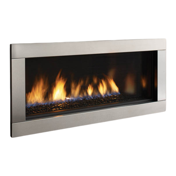
Regency Horizon
Gas Fireplace
Horizon HZ40E Product Video
WARNING
FIRE OR EXPLOSION HAZARD
Failure to follow safety warnings exactly could result in serious
injury, death, or property damage.
- Do not store or use gasoline or other flammable vapors and liquids in the vicinity of this or any other
appliance.
- WHAT TO DO IF YOU SMELL GAS
•
Do not try to light any appliance.
• Do not touch any electrical switch: do not use any phone in your building.
Leave the building immediately.
• Immediately call your gas supplier from a neighbour's phone. Follow the gas supplier's
instructions.
• If you cannot reach you gas supplier, call the fire department.
- Installation and service must be performed by a qualified installer, service agency or the gas supplier.
Tested by:
919-360
FPI FIREPLACE PRODUCTS INTERNATIONAL LTD. 6988 Venture St., Delta, BC Canada, V4G 1H4
®
Installer: Please complete the details on the back cover
and leave this manual with the homeowner.
Homeowner: Please keep these instructions for future reference.
HZ40E
Owners &
Installation Manual
MODELS:
HZ
40E
-NG10 Natural Gas
HZ
40E
-LP10 Propane
www.regency-fire.com
09.15.15
Advertisement
Table of Contents

Related Manuals for Regency Fireplace Products Horizon HZ40E-NG10


Summary of Contents for Regency Fireplace Products Horizon HZ40E-NG10
- Page 1 Regency Horizon HZ40E ® Owners & Installation Manual Gas Fireplace MODELS: -NG10 Natural Gas -LP10 Propane www.regency-fire.com Horizon HZ40E Product Video WARNING FIRE OR EXPLOSION HAZARD Failure to follow safety warnings exactly could result in serious injury, death, or property damage. - Do not store or use gasoline or other flammable vapors and liquids in the vicinity of this or any other appliance.
-
Page 2: Manufactured Mobile Home Requirements
MANUFACTURED MOBILE HOME REQUIREMENTS INFORMATION FOR MOBILE/MANUFACTURED HOMES AFTER FIRST SALE This Regency product has been tested and listed by Warnock Hersey/Intertek as a Direct Vent Wall Furnace to the following ® standards: VENTED GAS FIREPLACE HEATERS ANSI Z21.88-2014 / CSA 2.33-2014 and GAS-FIRED APPLIANCES FOR USE AT HIGH ALTITUDES CAN / CGA 2.17-M91. - Page 3 To the New Owner: Congratulations! You are the owner of a state-of-the-art Gas Fireplace by REGENCY . The HZ40E has been designed to provide ® you with all the warmth and charm of a fireplace at the flick of a switch. The model HZ40E has been approved by Warnock Hersey/Intertek for both safety and efficiency.
-
Page 4: Table Of Contents
table of contents Dura Vent Horizontal Termination ........37 Copy of Safety Decal .............5 Unit installation with Vertical Termination .....38 MA Code - CO Detector ..........6 High Elevation ..............39 Important Message ............8 Gas Line Installation ............39 Before You Start .............8 Pilot Adjustment ............39 General Safety Information ..........8 Gas Pipe Pressure Testing ..........39 Installation Checklist ............9... -
Page 5: Copy Of Safety Decal
safety decal This is a copy of the label that accompanies each HZ40E-NG10 and HZ40E-LP10 Direct Vent Gas Fireplace. We have printed a copy of the contents here for your review. NOTE: Regency units are constantly being improved. Check the label on the unit and if there is a difference, the label on the unit is the correct one. ®... -
Page 6: Ma Code - Co Detector
requirements MA Code - CO Detector (for the State of Massachusetts only) 5.08: Modifications to NFPA-54, Chapter 10 (2) Revise 10.8.3 by adding the following additional requirements: (a) For all side wall horizontally vented gas fueled equipment installed in every dwelling, building or structure used in whole or in part for residential purposes, including those owned or operated by the Commonwealth and where the side wall exhaust vent termination is less than seven (7) feet above finished grade in the area of the venting, including but not limited to decks and porches, the following requirements shall be satisfied:... - Page 7 dimensions (1092mm) (972mm) (902mm) Inner/Outer Faceplate 4 Piece Faceplate/Verona Surround Regency Horizon ® HZ40E-10 Gas Fireplace...
-
Page 8: Important Message
installation IMPORTANT MESSAGE 4. This appliance must be connected to the YOUNG CHILDREN SHOULD BE CARE- specified vent and termination cap to the outside SAVE THESE FULLY SUPERVISED WHEN THEY ARE of the building envelope. Never vent to another IN THE SAME AREA AS THE APPLI- INSTRUCTIONS room or inside a building. -
Page 9: Installation Checklist
installation 4. This appliance is Listed for bedroom installations INSTALLATION CHECKLIST This includes: using the standard Remote (thermostat system). Some areas may have further requirements, 1. Locate appliance 1. Clocking the appliance to ensure the correct check local codes before installation. a) Room location (Refer to "Locating Your Gas firing rate (rate noted on label 26,000 Btu/h fireplace"... -
Page 10: Clearances
installation CLEARANCES The clearances listed below are Minimum distances unless otherwise stated: A major cause of chimney related fires is failure to maintain required clearances (air space) to combustible materials. It is of the greatest importance that this fireplace and vent system be installed only in accordance with these instructions. Flue Clearances to Combustibles Clearance: Dimension... -
Page 11: Mantel Clearances
installation MANTEL CLEARANCES Due to the extreme heat this fireplace emits, the mantel clearances are critical. Combustible mantel clearances from top of front facing are shown in the diagram on the right. 13" (330mm) Combustible Material Note: Ensure the paint that is used on the mantel and the facing is "high quality"... -
Page 12: Unit Assembly Prior To Installation
installation UNIT ASSEMBLY PRIOR TO INSTALLATION The nailing Strips must be correctly positioned and attached before unit is slid into position. NAILING STRIPS The nailing strips come attached to the unit. There is 1 plate on each side. The side nailing strips are secured to the framing. IMPORTANT NOTE Framing depth measurement is noted with the nailing strips set as far forward on the firebox as possible. -
Page 13: Framing Dimensions
installation FRAMING DIMENSIONS NOTE: If not purchasing the optional steel stud kit - adhere to the same framing if purchasing steel studs elsewhere. The use of the optional kit is highly recommended as it was designed specifically for the product to facilitate ease of installation. Framing Description HZ40E... -
Page 14: Optional Framing Kit
HZ40E installation OPTIONAL FRAMING KIT OptiOnal framing kit 5. Secure horizontal steel header stud with 2 screws per side as per 1. Construct the wood framing, ensure inside dimensions are 53"W x 45- diagram. 1/2"H as shown below. Header stud 45-1/2"... -
Page 15: Wall Mount On / Off Switch And Remote Receiver Installation
installation WALL MOUNT ON / OFF SWITCH AND REMOTE RECEIVER INSTALLATION REQUIRED FOR ALL INSTALLATIONS - INCLUDING PROFLAME REMOTE CONTROLS IMPORTANT INSTALLATION NOTE: The Receiver must be placed inside the supplied (Low Voltage) junction type wall box and installed into the wall only. DO NOT INSTALL WITHIN THE CONFINES OF THE FIREPLACE. -
Page 16: Non-Combustible Requirements
installation NON-COMBUSTIBLE REQUIREMENTS * Installation of the Receiver must be completed before installing non-combustible facing. All three pieces (top, 2 sides) are supplied to meet the non combustible requirements. Calcium silicate board is a high - grade material Metal Stud (header) on edge 51-5/16"... -
Page 17: Framing & Finishing
installation FRAMING & FINISHING 1. Frame in the enclosure for the unit with framing material. 5. If material such as brick, stone, etc extends past the faceplate depth (3-1/4"), when finishing around the faceplate, the minimum opening dimensions noted IMPORTANT: The framed opening must be of non-combustible below must be adhered to ensuring for the removal of the faceplate and for material. - Page 18 Discoloration is not the responsibility of Regency Fireplace Products. This is out of the control of Regency Fireplace Products Ltd., therefore not covered under any part of the warranty policy.
-
Page 19: Exterior Vent Termination Requirements
installation EXTERIOR VENT TERMINATION REQUIREMENTS Minimum Clearance Requirements Canada Clearance above grade, veranda, porch, deck, or balcony 12"(30cm) 12"(30cm) Clearance to window or door that may be opened 12"(30cm) 9" (23cm) Clearance to permanently closed window Vertical clearance to ventilated soffit located above the terminal within a horizontal distance of 2 feet (61cm) 19"(48cm) 19"(48cm) from the center line of the terminal (check with the local code) -
Page 20: Rigid Pipe Cross Reference Chart
4DT-FS 4DFSP 4DFS SV4BF TM-4CS Trim Plate-Black 4DT-TP 4DFPB 4DcP SV4LA TM-4TP 20 | Regency Horizon ® HZ40E-10 Gas Fireplace Regency Fireplace Products . 6988 Venture St. . Delta, BC . Canada . V4G 1H4 . 604-946-5155 . www.regency-fi re.com... - Page 21 Never allow the vent to run downward - this could cause high temperatures and may present a possible fi re hazard. Regency Fireplace Products . 6988 Venture St. . Delta, BC . Canada . V4G 1H4 . 604-946-5155 . www.regency-fi re.com...
-
Page 22: Vent Restrictor Position
installation VENT RESTRICTOR POSITION Vent restriction is required for certain venting installations, see the diagrams in the "Venting Arrangements" section to determine if they are required for your installation. The Vent Restrictor plate is located on the inside top of the firebox. To set the vent restriction as indicated in the venting arrangements diagrams, refer to the following instructions;... -
Page 23: Venting Introduction
installation VENTING INTRODUCTION The HZ40E uses the "balanced flue" technology Co-Axial system. The inner liner vents products of combustion to the outside while the outer liner draws outside combustion air into the combustion chamber thereby eliminating the need to use heated room air for combustion and losing warm room air up the chimney. Note: These flue pipes must not be connected to any other appliance. -
Page 24: Horizontal Terminations Flex Vent
installation HORIZONTAL TERMINATIONS " FLEX VENT 4" X 6-7/8 These venting systems, in combination with the HZ40E Direct Vent Gas Fireplace, has been tested and listed as a direct vent heater system by Warnock Hersey/ Intertek. The location of the termination cap must conform to the requirements in the Vent Terminal Locations diagram in "Exterior Vent Termination Locations"... -
Page 25: Horizontal Terminations Rigid Pipe
installation HORIZONTAL TERMINATIONS " RIGID PIPE 4" X 6-5/8 The minimum components required for a basic horizontal termination are: Horizontal Termination Cap Elbow Rigid Pipe Adaptor (510-994. Wall Thimble Length of pipe to suit wall thickness (see chart) Wall thickness is measured from the back standoffs to the inside mounting surface of termination cap. -
Page 26: Horizontal Terminations Rigid Pipe
installation HORIZONTAL TERMINATIONS " RIGID PIPE 4" X 6-5/8 The diagrams below shows examples of horizontal termination arrangements using one, two, or three 90 elbows (two 45 elbows equal one 90 elbow) 1. A maximum of three 90 elbows are permitted (not including the starting 45 elbow at the flue collar when using rigid venting). - Page 27 installation Horizontal Venting with Two (2. 90 Elbows Horizontal Venting with Three (3. 90 Elbows One 90 elbow = Two 45 elbows. One 90 elbow = Two 45 elbows. Option H + H1 With these options, maximum Option H + H1 + H2 With these options, total pipe length is 28 feet maximum total pipe...
- Page 28 installation Horizontal Venting with Three (3. 90 Elbows One 90 elbow = Two 45 elbows. Option V + V1 H + H1 With these options, maximum total pipe 2' Min. 1' Max. 3' Min. 4' Max. length is 28 feet with minimum of 12 feet 3' Min.
-
Page 29: Vertical Terminations Rigid Pipe
installation VERTICAL TERMINATIONS " RIGID PIPE 4" X 6-5/8 Vertical Terminal The minimum components required for a basic vertical termination are: Vertical Termination Cap Storm Collar Elbow Rigid Pipe Adaptor (510-994. Term Flashing Ceiling Firestop Flashing Vinyl Siding Storm Collar Standoff (Optional) Length of pipe to suit wall thickness (see chart) -
Page 30: Venting Arrangement For Vertical Terminations
installation VENTING ARRANGEMENT FOR VERTICAL TERMINATIONS Vertical Venting with One(1. 90 Elbows (1 - 90 2 - 45 Horizontal (Feet) The shaded area in the diagram shows all allowable combinations of straight vertical and offset to vertical terminations, using one elbow, with Rigid Pipe Venting Systems. -
Page 31: Vertical Termination With Co-Linear Flex System
installation VERTICAL TERMINATION WITH CO-LINEAR FLEX SYSTEM THE APPLIANCE MUST NOT BE Masonry chimneys may take various contours which the flexible liner will accommodate. However, CONNECTED TO A CHIMNEY FLUE SERV- keep the flexible liner as straight as possible, avoid unnecessary bending. ING A SEPARATE SOLID FUEL BURNING APPLIANCE. -
Page 32: Vertical Terminations Rigid Pipe
installation VERTICAL TERMINATIONS " RIGID PIPE 4" X 6-5/8 • Two 45 elbows equal to one 90 elbow. Maximum of four 45 elbows allowed, not including the starting 45 elbow at the flue collar. • Vent must be supported at offsets. •... - Page 33 installation Vertical Venting with Three (3) 90 Elbows One 90 elbow = Two 45 elbows. Option H + H1 V + V1 1' Max. 1' Min. 3' Max. 3' Min. With these options, max. total pipe length is 30 feet with min. 2' Max.
-
Page 34: Venting Arrangements - Vertical Terminations
installation VENTING ARRANGEMENTS - VERTICAL TERMINATIONS with Co-linear Flex System for both Residential & Manufactured Homes into Masonry Fireplaces Vent Restrictor Set 2 Vent Restrictor Set 2 Vent Restrictor Vent Restrictor Set 2 Horizontal Distance (Feet) Horizontal Distance (Feet) Horizontal Distance (Feet) The shaded area in the diagrams show the allowable vertical terminations when using two- 3"... -
Page 35: Unit Installation With Horizontal Termination
installation 5. Assemble the desired combination of pipe and UNIT INSTALLATION WITH 7. Ensure that the pipe clearances to combustible elbows to the appliance adaptor and twist-lock materials are maintained (Diagram 3). Install HORIZONTAL TERMINATION for a solid connection. the termination cap. 4"... -
Page 36: Unit Installation With Horizontal Termination
installation UNIT INSTALLATION WITH NOTE: Horizontal sections must be supported ASTROCAP at intervals not exceeding 3 feet (0.9 DIMENSIONS (946-523/P) HORIZONTAL TERMINATION meter). (Flame picture and performance 4" X 6-5/8" VENTING will be affected by sags in the liner). (Flex Vent Systems) 4. -
Page 37: Dura Vent Horizontal Termination
installation DURA-VENT HORIZONTAL b) Horizontal runs of vent must be supported TERMINATIONS every three feet. Wall straps are available for this purpose. Install the vent system according to the manufacturer's instructions included with 5) Mark the wall for a 10" x 10" square hole. The the components. -
Page 38: Unit Installation With Vertical Termination
installation UNIT INSTALLATION WITH 4. Assemble the desired lengths of pipe and VERTICAL TERMINATION elbows. Ensure that all pipes and elbow con- 4" X 6-5/8" VENTING nections are in the fully twist-locked position and sealed. (Rigid Vent Systems) Maintain the 1-1/2" clearances (air spaces) to combustibles when passing through ceilings, Diagram 4 walls, roofs, enclosures, attic rafter, or other... -
Page 39: High Elevation
installation PILOT ADJUSTMENT 885 S.I.T. VALVE HZ40E-NG10 SYSTEM DATA DESCRIPTION Min. Supply 5" WC (1.25 kpa) Periodically check the pilot flames. Correct flame Pressure pattern has two strong blue flames: 1 flowing 1) 6 Stage flame adjustment around the flame sensor and 1 flowing across Manifold Pressure 3.5"... -
Page 40: Wiring Diagram
installation WIRING DIAGRAM Proflame System Configuration 886 GTMF Wire Diagram SureFire™ Switch AC Adaptor CAUTION: Label all wires prior to disconnection Caution: Ensure that the wires do not touch any when servicing controls. Wiring errors can cause hot surfaces and are away from sharp edges. improper and dangerous operation. -
Page 41: Optional Fan Installation - Initial Install
HZ40E installation OPTIONAL FAN INSTALLATION - INITIAL INSTALL OPTIONAL FAN INSTALLATION 120 Volt AC power is needed for the fan switch and blower. The fan can be 5. Connect one of the black wires from the power cord to the black wire hard wired if desired. - Page 42 HZ40E installation 11. Install the fan control module (FCM) into the bracket on the side access TO REMOVE THE FAN panel. Plug in the power cord to the outlet in the unit. Reinstall the panel with the 4 screws from step 10. 1.
-
Page 43: Optional Fan Installation - Existing Install
HZ40E installation OPTIONAL FAN INSTALLATION - EXISTING INSTALL OPTIONAL FAN INSTALLATION - INTO EXISTING INSTALLATIONS 120 Volt AC power is needed for the fan switch and blower. The fan can be hard wired if desired. The receptacle box should be installed on the left 9) Remove the left access plate by undoing the 8 screws - see locations hand side of the unit by a qualifi... - Page 44 installation HZ40E 9. Secure the fan to the base with 2 screws. Note the right access panel 15. The fan control module (supplied with the fan kit) secures to the side was removed to allow easier access to the right side screw. access panel.
-
Page 45: Wiring Diagram With Optional Fan
installation WIRING DIAGRAM WITH OPTIONAL FAN Proflame System Configuration 886 GTMF Wire Diagram SureFire™ Switch Ground Black White Neutral Black Green Live Ground 120V AC 60 Hz Black Black Fan Thermodisc (normally open) Caution: Ensure that the wires do not touch any CAUTION: Label all wires prior to disconnection hot surfaces and are away from sharp edges. -
Page 46: Optional Wall Thermostat Installation
installation OPTIONAL WALL THERMOSTAT INSTALLATION 4. Connect the other thermostat lead to male connector disconnected This installation must be completed during initial install with the front access from Step1using a female spade connector - see picture below. panel removed. A wall thermostat may be installed if desired. Recommended: The wall thermostat should be mounted beside the Remote/Unit Receiver which comes standard with the appliance. -
Page 47: Inner Panel Installation
installation HZ40E INNER PANEL INSTALLATION INNER PANEL INSTALLATION 7) Install the left side enamel panel - secure in position with the panel Handling Instructions clip and two tighten two screws loosened in step 2, as shown in the Black Enamel Panels diagram below. -
Page 48: Glass Crystals Or Optional Stones
installation GLASS CRYSTALS OR OPTIONAL STONES INSTALLATION ON BURNER Spread the Glass Crystals or Stones evenly over the burner. Ensure the crystals/stones do not overlap excessively as this will affect the flame pattern. IMPORTANT NOTE: Only the supplied approved Glass Crystals and Stones are to be used with these fireplaces. Use of any other type of glass crystals or stones can alter the unit's performance. -
Page 49: Optional Driftwood Log Set Installation
HZ54E/HZ40E installation OPTIONAL DRIFTWOOD LOG SET INSTALLATION HZ54E/HZ40E - LOG INSTALLATION Read the instructions below carefully and refer to the images. If the logs are broken do not use the unit until they are replaced. Broken logs can interfere with pilot operation. Improper positioning of the logs may create carbon build-up and can alter the unit's performance which is not covered under warranty. - Page 50 HZ54E/HZ40E installation 10. Position Left Log (2) by matching the log and template profi les exactly. 15. Place Front Left log piece on fi rebox fl oor as shown. HZ54E shown - Left Log (2) positioned to match HZ54E shown - Left Log Piece(6) template pro le.
-
Page 51: Glass Door Installation
installation GLASS DOOR INSTALLATION The glass door comes with a black trim. 2. With the door in proper position - secure with 3 screws in locations shown 1. To install the trim and glass door, simply hook the top door flange onto the in Diagram 3. -
Page 52: Safety Screen Removal / Installation
installation SAFETY SCREEN/INNER DOOR FRAME REMOVAL/ INSTALLATION SAFETY SCREEN / INNER DOOR FRAME REMOVAL/INSTALLATION THE INNER DOOR FRAME (3) MUST BE PURCHASED SEPARATELY IN EITHER STAINLESS STEEL OR BLACK 1. The inner door trim (1) and safety screen (2) come attached to the fireplace. 4. -
Page 53: Piece Faceplate Installation
installation HZ40E VERONA / 4 PIECE FACEPLATE INSTALLATION VERONA / 4 PIECE FACEPLATE INSTALLATION 1) When installing required Safety Screen - See "Safety Screen" instal- lation instructions. 2) Install brackets onto the back of the faceplate - 3 screws for each bracket in locations shown below. -
Page 54: Inner And Outer Door Frame Installation
installation OUTER DOOR FRAME INSTALLATION OUTER DOOR FRAME INSTALLATION Bracket in Unit 1. Install the outer door frame to the unit by hooking the left and right side mounting brackets into the mounting slots at the side of the firebox Tab on Faceplate as shown below. -
Page 55: Operating Instructions
operating instructions OPERATING NORMAL OPERATING INSTRUCTIONS SOUNDS OF GAS APPLIANCES 1. Read and understand these instructions before operating this appliance. It is possible that you will hear some sounds from your gas appliance. This is perfectly normal due to 2. Check to see that all wiring is correct and the fact that there are various gauges and types enclosed to prevent possible shock. -
Page 56: Lighting Procedure
operating instructions LIGHTING PROCEDURE IMPORTANT: The remote control system supplied with this appliance has 3. After approximately 4 seconds the spark ignition system will spark for 60 several options for starting/operating the appliance using the power button seconds to light the main burner. and ON/OFF key on the hand held transmitter. -
Page 57: Copy Of Lighting Plate Instructions
operating instructions COPY OF LIGHTING PLATE INSTRUCTIONS FOR YOUR SAFETY READ BEFORE LIGHTING This appliance must be installed in accordance with local codes, if any; if none, follow the National Fuel Gas Code, ANSI Z223.1/NFPA 54, or Natural Gas and Propane Installation Codes, CSA B149.1. WARNING: If you do not follow these instructions exactly, a fire or explosion may result causing property damage, personal injury or loss of life. -
Page 58: Maintenance Instructions
maintenance MAINTENANCE GLASS GASKET GENERAL VENT INSTRUCTIONS MAINTENANCE If the glass gasket requires replacement use a tadpole glass gasket (Part # 936-159.. Conduct an inspection of the venting system semi- 1. Always turn off the gas and electrical supply annually. Recommended areas to inspect as follows: before cleaning. -
Page 59: Valve Assembly Replacement
maintenance VALVE ASSEMBLY REPLACEMENT 8. Remove the burner by sliding it to the right - then lift out. 1. Turn the unit off and allow it to cool down to room temperature. 2. Shut off the gas and power supply to the unit. 3. -
Page 60: Main Assembly
parts list MAIN ASSEMBLY Part # Description Part # Description 256-038 Frame Door HZ40E 911-032 10 ft. wiring harness 940-361/P Glass Neoceram Flush HZ40E 910-572 Wall switch receiver 256-039 Bottom Tray HZ40E 910-576 Receiver wall plate (white) 256-525 Burner Assembly NG c/w Cap HZ40E 911-037 Flame Sensor 256-530... -
Page 61: Accessories
parts list ACCESSORIES Part # Description 5 pound bag of glass crystals 5 pound bag of firebeads 256-908 Black Enamel Inner Panels Part # Description Part # Description 258-954 Faceplate Black 946-775 Black Reflective Crystals 946-739 Black Firebeads 258-957 Faceplate Brushed Stainless 946-776 Copper Crystals 946-740... - Page 62 notes 62 | Regency Horizon ® HZ40E-10 Gas Fireplace...
-
Page 63: The Warranty: Limited Lifetime
warranty Gas Product Warranty 2015 Regency® Fireplace Products are designed with reliability and simplicity in mind. In addition, our internal Quality Assurance Team carefully inspects each unit thorough- ly before it leaves our facility. Regency® Fireplace Products is pleased to extend this limited lifetime warranty to the original purchaser of a Regency® Product. This warranty is not transferable. - Page 64 Register your Regency warranty online ® www.regency-fire.com Reasons to register your product online today! • View and modify a list of all your registered products. • Request automatic email notification of new product updates. • Stay informed about the current promotions, events, and special offers on related products.