Table of Contents
Advertisement
Quick Links
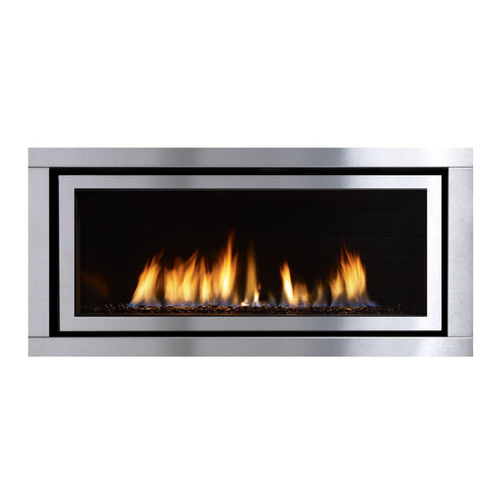
Regency Horizon ™ HZ40E
Horizon HZ40E Product Video
WARNING:
If the information in these instructions are not followed exactly,
a fi re or explosion may result causing property damage,
personal injury or loss of life.
FOR YOUR SAFETY
Do not store or use gasoline or other fl ammable vapors and
liquids in the vicinity of this or any other appliance.
Installation and service must be performed by a qualifi ed
installer, service agency or the gas supplier.
Tested by:
919-271
FPI FIREPLACE PRODUCTS INTERNATIONAL LTD. 6988 Venture St., Delta, BC Canada, V4G 1H4
Gas Fireplace
Installer: Please complete the details on the back cover
Installer
and leave this manual with the homeowner.
Homeowner: Please keep these instructions for future reference.
: Please complete the details on the back cover
Installation Manual
MODELS:
www.regency-fi re.com
FOR YOUR SAFETY
What to do if you smell gas:
Do not try to light any appliance
Do not touch any electrical switch:
do not use any phone in your
building.
Immediately call your gas supplier
from a neighbour's phone. Follow
the gas supplier's instructions.
If you cannot reach your gas
supplier, call the fi re department.
Owners &
HZ
40E
-NG2 Natural Gas
HZ
40E
-LP2 Propane
08/19/13
Advertisement
Table of Contents

Related Manuals for Regency Fireplace Products Regency Horizon HZ40E-NG2


Summary of Contents for Regency Fireplace Products Regency Horizon HZ40E-NG2
- Page 1 Regency Horizon ™ HZ40E Owners & Installation Manual Gas Fireplace MODELS: -NG2 Natural Gas -LP2 Propane www.regency-fi re.com Horizon HZ40E Product Video WARNING: FOR YOUR SAFETY If the information in these instructions are not followed exactly, What to do if you smell gas: a fi...
-
Page 2: Manufactured Mobile Home Requirements
MANUFACTURED MOBILE HOME REQUIREMENTS INFORMATION FOR MOBILE/MANUFACTURED HOMES AFTER FIRST SALE ® This Regency product has been tested and listed by Warnock Hersey/Intertek as a Direct Vent Wall Furnace to the following standards: VENTED GAS FIREPLACE HEATERS ANSI Z21.88-2009 / CSA 2.33-2009 and GAS-FIRED APPLIANCES FOR USE AT HIGH ALTITUDES CAN / CGA 2.17-M91. - Page 3 To the New Owner: Congratulations! You are the owner of a state-of-the-art Gas Fireplace by REGENCY ® . The HZ40E has been designed to provide you with all the warmth and charm of a fi replace at the fl ick of a switch. The model HZ40E has been approved by Warnock Hersey/Intertek for both safety and effi...
-
Page 4: Table Of Contents
TABLE OF CONTENTS Unit Installation with Horizontal Termination ....35 SAFETY DECAL Unit installation with Vertical Termination ....36 4" x 6-5/8" venting ............36 Copy of Safety Decal .............5 High Elevation Gas Line Installation ......37 Pilot Adjustment ............37 REQUIREMENTS Gas Pipe Pressure Testing ..........37 880 S.I.T. -
Page 5: Copy Of Safety Decal
SAFETY LABEL This is a copy of the label that accompanies each HZ40E-NG2 and HZ40E-LP2 Direct Vent Gas Fireplace. We have printed a copy of the contents here for your review. NOTE: Regency ® units are constantly being improved. Check the label on the unit and if there is a difference, the label on the unit is the correct one. -
Page 6: Requirements
REQUIREMENTS MA Code - CO Detector (for the State of Massachusetts only) 5.08: Modifications to NFPA-54, Chapter 10 (2) Revise 10.8.3 by adding the following additional requirements: (a) For all side wall horizontally vented gas fueled equipment installed in every dwelling, building or structure used in whole or in part for residential purposes, including those owned or operated by the Commonwealth and where the side wall exhaust vent termination is less than seven (7) feet above finished grade in the area of the venting, including but not limited to decks and porches, the following requirements shall be satisfied:... - Page 7 DIMENSIONS 49-5/16" 45-5/8" 18-5/16" 39-13/16" 1-7/16" 16-1/2" 36 4 " (1092mm) (972mm) (1238mm) (902mm) (914mm) Regency Horizon™ HZ40E-2 Gas Fireplace...
-
Page 8: Installation
INSTALLATION 11) U n d e r n o c i r c u m s t a n c e s h o u l d t h i s IMPORTANT MESSAGE YOUNG CHILDREN SHOULD BE CARE- appliance be modified. Parts that have SAVE THESE to be removed for servicing should be... -
Page 9: Installation Checklist
INSTALLATION 4) This appliance is Listed for bedroom This includes: INSTALLATION installations using the standard Remote CHECKLIST 1) Clocking the appliance to ensure the correct (thermostat system). Some areas may have fi ring rate (rate noted on label 26,000 Btu/h further requirements, check local codes before (NG), 25,500 Btu/h (LP) after burning appliance installation. -
Page 10: Clearances
INSTALLATION CLEARANCES The clearances listed below are Minimum distances unless otherwise stated: A major cause of chimney related fi res is failure to maintain required clearances (air space) to combustible materials. It is of the greatest importance that this fi replace and vent system be installed only in accordance with these instructions. WARNING Caution Requirements Fire hazard is an extreme risk... -
Page 11: Mantel Clearances
INSTALLATION MANTEL CLEARANCES Due to the extreme heat this fi replace emits, the mantel clearances are critical. Combustible mantel clearances from top of front facing are shown in the diagram on the right. 13" (330mm) Combustible Material Note: Ensure the paint that is used on the mantel and the facing is "high quality"... -
Page 12: Unit Assembly Prior To Installation
INSTALLATION UNIT ASSEMBLY PRIOR TO INSTALLATION The nailing Strips must be correctly positioned and attached before unit is slid into position. NAILING STRIPS The nailing strips come attached to the unit. There is 1 plate on each side, 1 on the top. There also two on the bottom. The top and side nailing strips are secured to the framing. -
Page 13: Framing Dimensions
INSTALLATION FRAMING DIMENSIONS Framing Description HZ40E Dimensions Framing Height 42” (1067mm) Framing Width 49-7/8" (1266mm) C1 Horizontal Vent 19-7/16" (495mm) Framing Depth C2 Vertical Vent 23-7/16" (596mm) Vertical rise -terminating horizontal Minimum Height to Combustibles 43-7/8" (1004mm) Corner Wall Depth 57-3/8"... -
Page 14: Wall Mount On / Off Switch And Battery Compartment Installation And/Or Receiver Installation
INSTALLATION WALL MOUNT ON / OFF SWITCH AND BATTERY COMPARTMENT INSTALLATION AND/OR RECEIVER INSTALLATION REQUIRED FOR ALL INSTALLATIONS - INCLUDING PROFLAME REMOTE CONTROLS MPORTANT INSTALLATION NOTE: The Receiver must be placed inside the supplied (Low Voltage) junction type wall box and installed into the wall only. DO NOT INSTALL WITHIN THE CONFINES OF THE FIREPLACE. -
Page 15: Non-Combustible Requirements
INSTALLATION NON-COMBUSTIBLE REQUIREMENTS * Installation of the Receiver must be completed before installing non-combustible facing. All three pieces (top, 2 sides) are now supplied to meet the non combustible requirements. Previously only the top was supplied. Metal Stud (header) on edge 51-5/16"... -
Page 16: Framing & Finishing
INSTALLATION FRAMING & FINISHING 5) If material such as brick, stone, etc extends past the faceplate depth (1-1/2"), 1) Frame in the enclosure for the unit with framing material. when fi nishing around the faceplate, the minimum opening dimensions noted below must be adhered to ensuring for the removal of the faceplate and for IMPORTANT: The framed opening must be of non-combustible the safe operation of this appliance. -
Page 17: Non-Combustible Requirements
INSTALLATION FRAMING & FINISHING Finished Nailing Strip Material Position 1/2" 1" Nailing Strip 1” Forward Unit 1" 1/2" Nailing Strip ½” Forward Note: Depending on the material used for fi nishing, the nailing strips must be set accordingly so that the fi nished material Unit is always at the 1-1/2"... -
Page 18: Exterior Vent Termination Requirements
INSTALLATION EXTERIOR VENT TERMINATION REQUIREMENTS Minimum Clearance Requirements Canada Clearance above grade, veranda, porch, deck, or balcony 12"(30cm) 12"(30cm) Clearance to window or door that may be opened 12"(30cm) 9" (23cm) Clearance to permanently closed window Vertical clearance to ventilated soffi t located above the terminal within a horizontal distance of 2 feet (61cm) 19"(48cm) 19"(48cm) from the center line of the terminal (check with the local code) -
Page 19: 4" X 6-5/8" Rigid Pipe
INSTALLATION 4” X 6-5/8” RIGID PIPE CROSS REFERENCE CHART ONLY Components from different Manufacturers may not be mixed. Not All Rigid Pipe components are available directly from FPI. Description Selkirk American Metal Security ICC Excel Simpson Metal-Fab™ Direct Temp™ Secure- Vent® Direct ®... - Page 20 INSTALLATION Description Selkirk American Metal Security ICC Excel Simpson Metal-Fab™ Direct Temp™ Secure- Vent® Direct Direct Vent Pro ® Products® Sure Seal Amerivent Direct Attic Insulation Shield 12” 46DVA-IS 4DAIS12 SV4RSA N/A@ FPI Attic Insulation Shield - 36” 4DAIS12 TM-4AS Cold Climates Basic Horizontal Termination Kit (A) Disc.
-
Page 21: Vent Restrictor Position
INSTALLATION VENT RESTRICTOR POSITION Vent restriction is required for certain venting installations, see the diagrams in the "Venting Arrangements" section to determine if they are required for your installation. The Vent Restrictor plate is located on the inside top of the fi rebox. To set the vent restriction as indicated in the venting arrangements diagrams, refer to the following instructions;... -
Page 22: Venting Introduction
INSTALLATION VENTING INTRODUCTION The HZ40E uses the "balanced fl ue" technology Co-Axial system. The inner liner vents products of combustion to the outside while the outer liner draws outside combustion air into the combustion chamber thereby eliminating the need to use heated room air for combustion and losing warm room air up the chimney. Note: These fl... -
Page 23: Horizontal Terminations
INSTALLATION HORIZONTAL TERMINATIONS " FLEX VENT 4" X 6-7/8 These venting systems, in combination with the HZ40E Direct Vent Gas Fireplace, has been tested and listed as a direct vent heater system by Warnock Hersey/ Intertek. The location of the termination cap must conform to the requirements in the Vent Terminal Locations diagram in "Exterior Vent Termination Locations"... -
Page 24: Horizontal Terminations
INSTALLATION HORIZONTAL TERMINATIONS " RIGID PIPE 4" X 6-5/8 The minimum components required for a basic horizontal termination are: Horizontal Termination Cap Elbow Rigid Pipe Adaptor (510-994) Wall Thimble Length of pipe to suit wall thickness (see chart) Wall thickness is measured from the back standoffs to the inside mounting surface of termination cap. -
Page 25: Horizontal Terminations
INSTALLATION HORIZONTAL TERMINATIONS " RIGID PIPE 4" X 6-5/8 The diagrams below shows examples of horizontal termination arrangements using one, two, or three 90 elbows (two 45 elbows equal one 90 elbow) 1) A maximum of three 90 elbows are permitted (not including the starting 45 elbow at the fl... - Page 26 INSTALLATION Horizontal Venting with Two (2) 90 Elbows Horizontal Venting with Three (3) 90 Elbows One 90 elbow = Two 45 elbows. One 90 elbow = Two 45 elbows. Option H + H1 With these options, maximum Option H + H1 + H2 With these options, maximum total pipe total pipe length is 28 feet...
- Page 27 INSTALLATION Horizontal Venting with Three (3) 90 Elbows One 90 elbow = Two 45 elbows. Option V + V1 H + H1 With these options, maximum total pipe 2' Min. 1' Max. 3' Min. 4' Max. length is 28 feet with minimum of 12 feet 3' Min.
-
Page 28: Vertical Terminations
INSTALLATION VERTICAL TERMINATIONS " RIGID PIPE 4" X 6-5/8 The minimum components required for a basic vertical termination are: Vertical Termination Cap Vertical Terminal Elbow Rigid Pipe Adaptor (510-994) Ceiling Firestop Flashing Storm Collar Storm Collar Length of pipe to suit wall thickness (see chart) Flashing Galvanized pipe is desirable above the roofl... -
Page 29: Venting Arrangement For Vertical Terminations
INSTALLATION VENTING ARRANGEMENT FOR VERTICAL TERMINATIONS Vertical Venting with One(1) 90 Elbows (1 - 90 2 - 45 Horizontal (Feet) The shaded area in the diagram shows all allowable combinations 18 18 of straight vertical and offset to vertical terminations, using one elbow, with Rigid Pipe Venting Systems. -
Page 30: Vertical Termination With Co-Linear Flex System
INSTALLATION VERTICAL TERMINATION WITH CO-LINEAR FLEX SYSTEM THE APPLIANCE MUST NOT BE Masonry chimneys may take various contours which the fl exible liner will accommodate. However, CONNECTED TO A CHIMNEY FLUE SERV- keep the fl exible liner as straight as possible, avoid unnecessary bending. ING A SEPARATE SOLID FUEL BURNING APPLIANCE. -
Page 31: Vertical Terminations
INSTALLATION VERTICAL TERMINATIONS " RIGID PIPE 4" X 6-5/8 • Two 45 elbows equal to one 90 elbow. Maximum of four 45 elbows allowed, not including the starting 45 elbow at the fl ue collar. • Vent must be supported at offsets. •... - Page 32 INSTALLATION Vertical Venting with Three (3) 90 Elbows One 90 elbow = Two 45 elbows. Option H + H1 V + V1 With these options, max. total 1' Max. 1' Min. 3' Max. 3' Min. pipe length is 30 feet with min. 2' Max.
-
Page 33: Venting Arrangements - Vertical Terminations
INSTALLATION VENTING ARRANGEMENTS - VERTICAL TERMINATIONS with Co-linear Flex System for both Residential & Manufactured Homes into Masonry Fireplaces Vent Restrictor Set 2 Vent Restrictor Set 2 Vent Restrictor Vent Restrictor Set 2 Horizontal Distance (Feet) Horizontal Distance (Feet) Horizontal Distance (Feet) The shaded area in the diagrams show the allowable vertical terminations when using two- 3"... -
Page 34: Unit Installation With Horizontal Termination
INSTALLATION 5) Assemble the desired combination of pipe and UNIT INSTALLATION 7) Ensure that the pipe clearances to combustible elbows to the appliance adaptor and twist-lock materials are maintained (Diagram 5). Install WITH HORIZONTAL for a solid connection. the termination cap. TERMINATION Note: If installing termination on a vinyl siding 4"... -
Page 35: Unit Installation With Horizontal Termination
INSTALLATION ASTROCAP UNIT INSTALLATION NOTE: Horizontal sections must be supported at intervals not exceeding 3 feet (0.9 DIMENSIONS (946-523/P) WITH HORIZONTAL meter). (Flame picture and performance will be affected by sags in the liner). TERMINATION 4) Separate the 2 halves of the wall thimble and 4"... -
Page 36: Unit Installation With Vertical Termination
INSTALLATION UNIT INSTALLATION 4) Assemble the desired lengths of pipe and elbows. Ensure that all pipes and elbow con- WITH VERTICAL nections are in the fully twist-locked position and sealed. TERMINATION 4" X 6-5/8" VENTING (Rigid Vent Systems) Diagram 4 1) Maintain the 1-1/2"... -
Page 37: High Elevation Gas Line Installation
INSTALLATION PILOT ADJUSTMENT 880 S.I.T. VALVE HZ40E-NG2 SYSTEM DATA DESCRIPTION Min. Supply 5" WC (1.25 kpa) Periodically check the pilot fl ames. Correct fl ame Pressure pattern has two strong blue fl ames: 1 fl owing Manifold Pressure 3.5" WC (0.87 kpa) around the fl... -
Page 38: Ac Power Adaptor Installation
INSTALLATION AC POWER ADAPTOR INSTALLATION (FOR SUREFIRE SYSTEMS) An optional AC power adaptor may be installed as a constant power source for the SureFire system. NOTE: AC power adaptor is not required when using GTMF Remote IMPORTANT: Recommend removing the 4-AA batteries in the SureFire receiver. This will avoid battery leakage and power drainage. -
Page 39: Wiring Diagram
INSTALLATION WIRING DIAGRAM This heater does not require a 120V A.C. supply for operation. In case of a power failure, the burner switch and the optional remote control/thermostat will continue to operate. However, a 120V A.C. power supply is needed for the fan/blower operation. (Do not cut the ground terminal off under any circumstances.) NOTE: Even if the fan is not purchased with the unit, it is still a good idea to bring power to the receptacle box (provided with the unit) in case the fan is installed at a later date. -
Page 40: Profl Ame System Gtmf With Optional Fan
INSTALLATION PROFLAME SYSTEM GTMF WITH OPTIONAL FAN Proflame System Configuration 886 GTMF Wire Diagram SureFire™ Switch Ground Black White Neutral Black Green Live Ground 120V AC 60 Hz Black Black Fan Thermodisc (normally open) Caution: Ensure that the wires do not touch any hot surfaces and are away from sharp edges. -
Page 41: Optional Fan Wiring Diagram
INSTALLATION OPTIONAL FAN WIRING DIAGRAM WITHOUT PROFLAME GTMF SYSTEM Lockwasher Ground Star washer #8 Ground Lug (for mobile home) Black White Neutral Black Green Live Ground 120V AC 60 Hz Black Black Fan Thermodisc ground wire (normally open) Electrical Connection Alternative Scheme "A", Power at Stove Electrical Connection Alternative Scheme "B", Power at Switch... -
Page 42: Optional Remote Control
INSTALLATION Optional RECEIVER WALL SWITCH (Included with Unit) REMOTE CONTROL 1) Run the supplied 10' of the wire harness through the right or left side gas inlet opening- connect the ON/OFF wire harness. Be careful not to damage Use the Regency ®... -
Page 43: Gtmf Remote Installation
INSTALLATION GTMF REMOTE INSTALLATION 120 Volt AC power is needed for the fan. The fan can be hard wired if desired. INTO EXISTING INSTALLATIONS The receptacle box should be installed on the right hand side of the unit by a qualifi ed electrician. The neutral (wider) slot of the polarized receptacle 1) Shut off the gas and power supply to the unit. - Page 44 INSTALLATION 8) Once the top panel is removed - the left side panel will be accessible. 5) Loosen 2 screws at the back of the burner to release it. Remove 3 screws from the left side access panel in locations shown below.
- Page 45 INSTALLATION 11) Locate the digital fi rebox control box. 12) Plug the fan power cord into the fan control module in the outlet marked fan. Plug in the FCM wire (from the digital fi rebox control box wire har- ness) into the location on the fan control module marked com FCM Wire 13) See Profl...
-
Page 46: Optional Fan Installation
INSTALLATION OPTIONAL FAN INSTALLATION 120 Volt AC power is needed for the fan switch and blower. The fan can be 5) Connect one of the black wire to the Black wires from the power cord. hard wired if desired. The receptacle box should be installed on the left (light blue connector). -
Page 47: Optional Fan Installation - Into Existing Installations
INSTALLATION OPTIONAL FAN INSTALLATION - INTO EXISTING INSTALLATIONS 120 Volt AC power is needed for the fan switch and blower. The fan can be 7) Loosen 3 screws at the back of the burner to release it. hard wired if desired. The receptacle box should be installed on the left hand side of the unit by a qualifi... - Page 48 INSTALLATION 10) Maneouver fan through left access panel opening. 11) To complete fan installation - follow steps 2- 7 on previous page. NOTE: The right access panel wasremoved to allow easier access to secure the right screw on the fan base. 12) Reverse steps 9-1 to complete install.
-
Page 49: Inner Panel Installation
INSTALLATION INNER PANEL INSTALLATION 7) Install the left side enamel panel - secure in position with the panel Handling Instructions clip and two tighten two screws loosened in step 2, as shown in the diagram below. Black Enamel Panels • Black Enamel panels must be inspected for scratches and dimples prior to installation. -
Page 50: Glass Crystals Or Optional Stones
INSTALLATION GLASS CRYSTALS OR OPTIONAL STONES INSTALLATION ON BURNER Spread the Glass Crystals or Stones evenly over the burner. Ensure the crystals/stones do not overlap excessively as this will affect the fl ame pattern. IMPORTANT NOTE: Only the supplied approved Glass Crystals and Stones are to be used with these fi replaces. Use of any other type of glass crystals or stones can alter the unit's performance, any damage caused by the use of any unapproved glass or stones will not be covered under warranty. - Page 51 INSTALLATION Glass Crystals shown on Burner Optional Spa Stones + Glass Crystals shown on burner. For Units HZ54E, , HZ42ST, HZ42STE, HZI234E, HZ42E, HZ42, For Units HZ54E, HZ42ST, HZ42STE, HZI234E, HZ42, HZ42E, HZ30E, HZ30E HZO42, HZO42 (AUS) PTO30, PTO60, Plateau Series Natural River Pebbles shown surrounding the a Horizon Burner Glass Crystals shown surrounding the Burner Glass Crystals shown on Burner and Firebox Floor...
-
Page 52: Optional Driftwood Log Set Installation
INSTALLATION OPTIONAL DRIFTWOOD LOG SET INSTALLATION Read the instructions below carefully and refer to the images. If the logs are broken do not use the unit until they are replaced. Broken logs can interfere with pilot operation. Improper positioning of the logs may create carbon build-up and can alter the unit's performance which is not covered under warranty. *Satin black paint is included if touch ups are required. - Page 53 INSTALLATION 10. Position Left Log (2) by matching the log and template profi les exactly. 15. Place Front Left log piece on fi rebox fl oor as shown. HZ54E shown - Left Log (2) positioned to match HZ54E shown - Left Log Piece(6) template profi...
-
Page 54: Glass Door Installation
INSTALLATION GLASS DOOR INSTALLATION The glass door comes with a black frame. 2) With the door in proper position - secure with 2 screws in locations shown in Diagram 3. 1) To install the frame and glass door, simply hook the top door fl ange onto the top of the unit and swing the door towards the unit, Diagram 1. -
Page 55: Optional Mesh Glass Guard
INSTALLATION OPTIONAL MESH GLASS GUARD 3) Install mesh screen, fl ush side facing out. 1) Remove left side and right side door frame screws. 4) Install left side and right side top mounting clips approximately 3" from each side. NOTE: Clips should line up with the edge of the outer edge of the glass door fl... -
Page 56: Piece Faceplate Installation
INSTALLATION 4 PIECE FACEPLATE INSTALLATION 1) If installing optional mesh glass guard - See optional "Mesh Glass Guard" installation instructions. 2) Install brackets onto the back of the faceplate - 3 screws for each bracket in locations shown below. Hook bracket over these tabs 3) To install the 4 pc. -
Page 57: Inner And Outer Door Frame Installation
INSTALLATION INNER AND OUTER DOOR FRAME INSTALLATION Note: HZ40E only - if installing optional mesh glass guard - Bracket in Unit See optional mesh glass guard instruction in the manual. Tab on Faceplate 1) Install 4 magnets onto 4 corners of glass frame prior to installing the inner door frame. -
Page 58: Operating Instructions
OPERATING INSTRUCTIONS OPERATING LIGHTING NORMAL OPERATING INSTRUCTIONS PROCEDURE SOUNDS OF GAS APPLIANCES IMPORTANT 1) Read and understand these instructions before To ignite or reignite the pilot, you operating this appliance. It is possible that you will hear some sounds from must fi... -
Page 59: Copy Of Lighting Plate Instructions
OPERATING INSTRUCTIONS INSTALLATION COPY OF LIGHTING PLATE INSTRUCTIONS FOR YOUR SAFETY READ BEFORE LIGHTING This appliance must be installed in accordance with local codes, if any; if none, follow the National Fuel Gas Code, ANSI Z223.1/NFPA 54, or Natural Gas and Propane Installation Codes, CSA B149.1. WARNING: If you do not follow these instructions exactly, a fire or explosion may result causing property damage, personal injury or loss of life. -
Page 60: Maintenance Instructions
MAINTENANCE MAINTENANCE GLASS GASKET GENERAL VENT INSTRUCTIONS MAINTENANCE If the glass gasket requires replacement use a tadpole glass gasket (Part # 936-159). Conduct an inspection of the venting system semi- 1) Always turn off the gas and electrical supply annually. Recommended areas to inspect as follows: before cleaning. -
Page 61: Valve Assembly Replacement
MAINTENANCE VALVE ASSEMBLY REPLACEMENT 8) Remove the burner by sliding it to the right - then lift out. 1) Turn the unit off and allow it to cool down to room temperature. 2) Shut off the gas and power supply to the unit. 3) Remove the faceplate or door frame -see instruction in this manual. -
Page 62: Parts List
PARTS LIST MAIN ASSEMBLY Part # Description Part # Description 256-038 Frame Door HZ40E 911-024 Valve NG 880 SIT IPI 940-361/P Glass Neoceram Flush HZ40E 911-025 Valve LP 880 SIT IPI 256-039 Bottom Tray HZ40E 911-006 Pilot Assembly IPI NG 256-525 Burner Assembly NG c/w Cap HZ40E 911-007... -
Page 63: Accessories
PARTS LIST ACCESSORIES Part # Description Part # Description 256-908 Black Enamel Inner Panels 946-700 GT Remote Control 946-701 GTM Remote Control 256-954 Faceplate Black 946-702 GTMF Remote Control 256-956 Faceplate Sunset Bronze 256-957 Faceplate Brushed Stainless 946-693 Modulator NG 946-694 Modulator LP 256-934... - Page 64 NOTES Regency Horizon™ HZ40E-2 Gas Fireplace...
- Page 65 NOTES Regency Horizon™ HZ40E-2 Gas Fireplace...
- Page 66 NOTES Regency Horizon™ HZ40E-2 Gas Fireplace...
-
Page 67: Warranty
WARRANTY ® Regency Fireplace Products are designed with reliability and simplicity in mind. In addition, our internal Quality Assurance Team carefully inspects each unit thoroughly before it leaves our facility. Regency ® Fireplace Products is pleased to extend this limited lifetime warranty to the original purchaser of a Regency ®... - Page 68 ® Register your Regency warranty online www.regency-fi re.com Reasons to register your product online today! • View and modify a list of all your registered products. • Request automatic email notifi cation of new product updates. • Stay informed about the current promotions, events, and special offers on related products.