Table of Contents
Advertisement
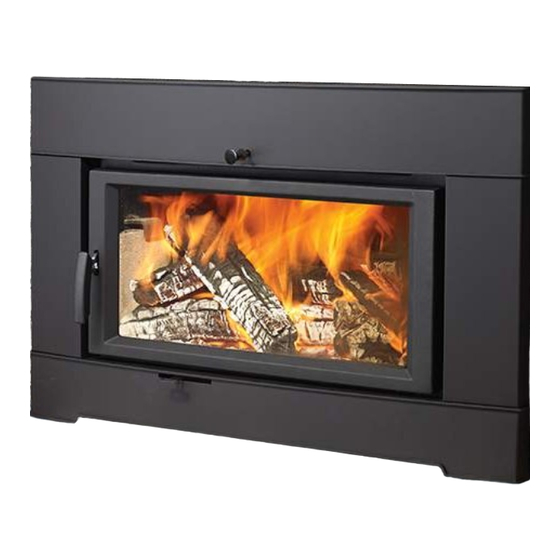
Wood
Fireplace
Insert
Owners & Installation Manual
www.regency-fire.com
MODEL:
CI2600/HI400
Installer: Please complete the details on the back cover
and leave this manual with the homeowner.
Homeowner: Please keep these instructions for future reference.
Report #219-S-17-2
FPI FIREPLACE PRODUCTS INTERNATIONAL LTD. 6988 Venture St., Delta, BC Canada, V4G 1H4
03.16.15
919-300c
Advertisement
Table of Contents

Related Manuals for Regency Fireplace Products CI2600


Summary of Contents for Regency Fireplace Products CI2600
- Page 1 Fireplace Insert Owners & Installation Manual www.regency-fire.com MODEL: CI2600/HI400 Installer: Please complete the details on the back cover and leave this manual with the homeowner. Homeowner: Please keep these instructions for future reference. Report #219-S-17-2 FPI FIREPLACE PRODUCTS INTERNATIONAL LTD. 6988 Venture St., Delta, BC Canada, V4G 1H4 03.16.15...
- Page 2 The following statements are required by the Environmental Protection Agency: "This manual describes the installation and operation of the Regency CI2600/HI400 catalytic equipped heater. This heater meets the U.S. ENVIRONMENTAL PROTECTION AGENCY’s emission limits for wood heaters built on or after July 1 1990.
-
Page 3: Table Of Contents
Safety Label For CI2600 ......................4 Dimensions - Contemporary faceplate ..................5 Dimensions - Low profile faceplate ..................6 Dimensions - cast faceplate ....................6 Dimensions - Standard Backing Plate ..................7 Dimensions - Oversized Backing Plate ..................7 before installing your insert ...................... -
Page 4: Safety Label For Ci2600
SAFETY LABEL FOR CI2600 This is a copy of the label that accompanies your Regency Insert. We have printed a copy of the contents here for your review. NOTE: Regency units are constantly being improved. Check the label on the unit and if there is a difference, the label on the unit is the correct one. -
Page 5: Dimensions - Contemporary Faceplate
DIMENSIONS - CONTEMPORARY FACEPLATE 28-7/8" (733mm) 18-1/2" (469mm) 40" (1016mm) 13-3/8" (340mm) 23-3/16" (589mm) 27-3/4" (750mm) CI2600/HI400 | wood insert... -
Page 6: Dimensions - Low Profile Faceplate
DIMENSIONS - LOW PROFILE FACEPLATE 40" [1016mm] 29" [737mm] DIMENSIONS - CAST FACEPLATE 41-3/8" 1051mm Standard Cast Faceplate shown above Oversized Cast Faceplate Dimensions: 44" W x 31" H CI2600/HI400 | wood insert... -
Page 7: Dimensions - Standard Backing Plate
DIMENSIONS - STANDARD BACKING PLATE DIMENSIONS - OVERSIZED BACKING PLATE CI2600/HI400 | wood insert... -
Page 8: Before Installing Your Insert
NEY SYSTEM SERVICING ANOTHER APPLI- removed. ANCE OR AN AIR DISTRIBUTION DUCT. b. The chimney damper may be removed to 8. DO NOT INSTALL IN A SLEEPING ROOM. install the chimney liner. CI2600/HI400 | wood insert... -
Page 9: Masonry And Factory Built Fireplace Clearances
Compare proposed system R of 1.231 to (hr)(ft (m)(K) (hr)(ft)( R = 1/k x T = 1/0.84 x .75 = 0.893. specified R of 0.893. Since proposed system R is greater than required, the system is Thermal Resistance: acceptable. )(hr)( )(K) CI2600/HI400 | wood insert... -
Page 10: Installing Your Insert
- slide forward to remove. Remove Fork 4. From inside the firebox - remove 7/16" bolt at back of firebox to remove B- Combustor Flame Shield - loosen 2 x 7/16" the flue collar. bolts to remove. CI2600/HI400 | wood insert... - Page 11 Ensure Upper Shield is centered in between 2 (two) vertical pins from front to back. When positioning the upper shield locate the vertical pins by feel. When the shield parts are in place - slide to the back. E - Upper Shield - orientation for reinstall CI2600/HI400 | wood insert...
-
Page 12: Installation Into A Masonry Fireplace
This screw is located in its position to prevent the liner/adaptor from coming into contact with the bypass rod. Please do not remove. This must remain in place at all times. Flush Inserts CI2600/HI400 | wood insert... -
Page 13: Levelling Bolts
Leveling Bolt Remove Bricks 2. Remove the three side bricks on each side then remove the corner bottom/side cut brick to gain access to the rear leveling bolts. You can adjust using a 9/16" wrench or socket CI2600/HI400 | wood insert... -
Page 14: Optional Cast Grill Installation
FIREBRICK ASSEMBLY Firebrick is included to extend the life of your insert and radiate heat more evenly. Check to see that all firebricks are in their correct positions and have not become misaligned during shipping. CI2600/HI400 | wood insert 919-400 01.13.15... -
Page 15: Optional Backing Plate Installation
1. Slide the backing plate over unit. Line up fl ange on backing plate with fl ange on unit and secure with 2 screws from the underside as shown below. Proceed with Faceplate install. Backer Plate Screws Diagram 4 Completed backing plate shown with Optional Hampton faceplate CI2600/HI400 | wood insert 12/18/14 919-324... -
Page 16: Contemporary Faceplate Installation
3. Install the left and right of the fascia panels using four 7/16’’ bolts. Back view of Top Fascia Panel lining up with the brackets installed in Step 1 Fascia side panels installed with Bolts CI2600/HI400 | wood insert 919-321 04/15/14... - Page 17 6. With door in closed position, take the bottom fascia and line up the wheels and rails with the rails on the unit. Once lined up lift up and into the rail system and slide into position. Rail System 7. Re-install bypass ring and door. Final Install CI2600/HI400 | wood insert...
-
Page 18: Low Profile Faceplate Installation
Left Bracket Right Bracket 3. Remove the ring on the bypass rod by turning counter clockwise - pull bypass rod forward to the open position. Install fan switch assembly Remove ring from the bypass rod CI2600/HI400 | wood insert 919-322a 03/24/14... - Page 19 Step 1. 7/16" bolts on back of Faceplate 8. Tighten the 7/16’’ bolts on the back of the Flat Faceplate 9. Re-install bypass ring and door. CI2600/HI400 | wood insert 919-322a 04/15/14...
-
Page 20: Cast Faceplate Installation
7/16’’ bolts. If screw holes already present on unit, line up defl ector with corre- sponding screw holes and secure with 2 screws on locations shown below. Cast Panel Shown Fan defl ector screw locations 919-323b 06/25/14 CI2600/HI400 | wood insert... - Page 21 Lift the fascia panel up slightly - push back to engage the brackets installed on Note: If installing optional cast grill - follow installation instructions in this Step 1. manual. Self adhesive gasket CI2600/HI400 | wood insert 919-323b 06/25/14...
-
Page 22: Oversize Cast Faceplate Installation
If screw holes already present on unit, line up defl ector with corre- sponding screw holes and secure with 2 screws on locations shown below. 3. Identify left and right side panels Left Panel/ Back Side Right Panel/ Back Side Fan defl ector screw locations 919-411 09/15/14 CI2600/HI400 | wood insert... - Page 23 Back view of Top Fascia Panel lining up with the brackets on Side Panels 8. Re-install bypass rod and ring Gasket Completed Optional Hampton Rail System Oversize Cast Faceplate Note: If installing optional cast grill - follow installation instructions in the manual. CI2600/HI400 | wood insert 919-411 09/15/14...
-
Page 24: Optional Fan/Blower Installation
2 screws, or use washers with holes in fan cassette mounting bracket and nuts for Cast Faceplate to lower fas- on right and left sides. cia before sliding faceplate into position. Fan switch assembly CI2600/HI400 | wood insert 919-320a 04/1514... - Page 25 Do not CAUTION: Label all wires prior cut or remove the grounding to disconnection when servicing prong from this plug. controls. Wiring errors can cause improper and dangerous operation. 919-320a 04/15/14 CI2600/HI400 | wood insert...
-
Page 26: Removable Door Handle
26 | REMOVABLE DOOR HANDLE The CI2600/HI400 has a removable door handle that can be stored when not in use. All the faceplates have a storage hook on the left side that accommodates the handle. Hook Handle The cool to touch door handle is designed to be inserted from the bot- tom up and slide off when not held in place. -
Page 27: Operating Instructions
- slide to the left to open, and to decrease - is for fire start-up only, as unit may slide to the right closed. The CI2600/HI400 unit has overheat if door is left open for too 12. Before opening your door to reload, open the... -
Page 28: Ash Disposal
Always ensure areas on the the burning season for creosote build-up. hearth are clean and ashes, debris etc. are not pushed towards the bottom of the fascia. Always brush and clean debris away from the unit, not towards. CI2600/HI400 | wood insert... -
Page 29: Troubleshooting Guide
Burning coal will cause a sulfur-based compound to coat the catalyst. Revert to burning wood and fire the combustor to elevated temperatures for one hour. CI2600/HI400 | wood insert... -
Page 30: Catalytic Combustor (Part # 106-534)
14.000 Mass = 4.649 pounds TOTAL AREA FOR AIR FLOW = 37.396 3RD ANGLE PROJECTION NOTE: SCREW METAL WRAP CI2600/HI400 | wood insert TOGETHER CAREFULLY BY HAND INSI TO PREVENT DAMAGE TO CATALYST. DO NOT SCALE AVOID USING POWER TOOL. -
Page 31: Optional Digital Catalytic Combustor Monitor
NOTE: 1/4" drill bit required for this installation. 5. Take your temperature probe and measure from end 3’’ and make a mark. The CI2600/HI400 is equipped with a provision to accept a catalytic tempera- Insert the temperature probe to the mark. -
Page 32: Combustor Assembly
Bypass Door Gasket Replacement. NOTE: Replacement combustors can be retrieved from Applied Ceramics or Contact your local Regency Dealer for details. DO NOT OPERATE THE APPLIANCE IF COMBUSTOR BECOMES INACTIVE - DO NOT OPERATE WITHOUT COMBUSTOR. CI2600/HI400 | wood insert... -
Page 33: Bypass Door Gasket Replacement
3. Lift off bypass plate, remove bypass gasket and replace with a new one. A -Primary Air Shield - loosen 2 x 7/16" bolts - slide forward to remove. Bypass plate Bypass gasket B- Combustor Flame Shield - loosen 2 x 7/16" bolts to remove. CI2600/HI400 | wood insert... - Page 34 When the shield parts are in place - slide to the back. E - Upper Shield - orientation for reinstall Upper Shield - center between 2 vertical pins 6. Reinstall Combustor/Flame Combustor Shield / Primary Air Shield and Bypass Rod. CI2600/HI400 | wood insert...
-
Page 35: Door Gasket
Use only high temperature anti seize lube. (ie. never seize) Check glass for cracks Replace if required. Clean blower motor Disconnect power supply. Remove and clean blower. *DO NOT LUBRICATE* Inspect and clean chimney Annual professional chimney cleaning recommended. CI2600/HI400 | wood insert... -
Page 36: Secondary Air Tube Removal
Align tab on right side air channel with notch on right hand end of air tube. Firmly grip center of air tube with vise grips, use hammer to tap vise grips from left to right until the tube bottoms out into the air channel on right. CI2600/HI400 | wood insert... -
Page 37: Cast Bypass Top Plate Removal
NOT REMOVE the bolts on the cast bypass prior to supporting the weight to avoid damage and injury. Cast bypass opening View of inside top of stove 6. Remove the cast bypass opening top plate and replace. 7. Reverse steps to reinstall. CI2600/HI400 | wood insert... -
Page 38: Main Assembly
Oversize Backing Plate 919-300 Manual 156-241 Cast Handle 156-514 Handle Assembly 106-561 Catch Assembly 106-131F 106-131F Door Catch Shims (Each) 106-043 Andirons (ea) 106-016 Bypass rod 106-122B Bypass knob (Matt Black) 106-122MJE Bypass knob (Timberline brown) CI2600/HI400 | wood insert... - Page 39 | 39 CI2600/HI400 | wood insert...
-
Page 40: Brick Layout
40 | BRICK LAYOUT 106-960 Brick Set - Complete CI2600/HI400 | wood insert... - Page 41 | 41 CI2600/HI400 | wood insert...
-
Page 42: Warranty
42 | Regency Fireplace Products are designed with reliability and simplicity in mind. In addition, our internal Quality Assurance Team carefully inspects each unit thoroughly before it leaves our door. is pleased to extend this limited lifetime warranty to the FPI Fireplace Products International Ltd. - Page 43 Versagrid Catalytic Converter, including any warranty or merchantability of fi tness for a particular use. NO LABOR WILL APPLY. All warranty claims must be sent to: Regency Fireplace Products By Authorized Regency Dealer * Prices subject to change.
- Page 44 Register your Regency warranty online ® www.regency-fire.com Reasons to register your product online today! • View and modify a list of all your registered products. • Request automatic email notification of new product updates. • Stay informed about the current promotions, events, and special offers on related products.