Table of Contents
Advertisement
Advertisement
Table of Contents

Related Manuals for Datamax H Class


Summary of Contents for Datamax H Class
- Page 1 Operator’s Manual...
-
Page 3: Important Safety Instructions
Important Safety Instructions This printer has been carefully designed to provide years of safe, reliable performance. As with all electrical equipment, there are a few basic precautions you should take to avoid hurting yourself or damaging the printer: > Carefully read the installation and operating instructions provided with your printer. >... -
Page 4: Copyright Information
Information in this document is subject to change without notice and does not represent a commitment on the part of Datamax Barcode Products Corporation. No part of this manual may be reproduced or transmitted in any form or by any means, for any purpose other than the purchaser's personal use, without the expressed written permission of Datamax Corporation. - Page 5 Agency Compliance and Approvals UL60950-1: 2003 1 Edition CSA C22.2 No. 60950-1-03 1 Edition; April 2003 EN60950 For 230 Volt Operation (Europe): Use a cord set, marked "HAR," consisting of a min H05VV-F cord which has a minimum 0.75 square mm diameter conductors, provided with an IEC 320 receptacle and a male plug for the country of installation rated 6A, 250V Für 230 Volt (Europa): Benützen Sie ein Kabel, das mit "HAR"...
-
Page 7: Table Of Contents
Contents Printer Overview.................. 1 Media Selection ........................2 Printer Connections ................5 Connecting Power........................5 Interface Connections ......................6 Media Loading ................... 21 Loading Roll Media ......................21 Loading Fan-fold and Externally Supplied Media..............24 Loading the Internal Rewinder ..................... 25 Loading Ribbon ................. - Page 8 Embedded Fonts........................ 127 Embedded Bar Codes......................130 Appendix C - Module File Definitions..........135 Appendix D - Multi-Language Downloads ........137 Appendix E - Saving a Configuration File........142 Glossary ................... 145 Warranty Statement ................ 149 Contact Datamax ................151...
-
Page 9: Printer Overview
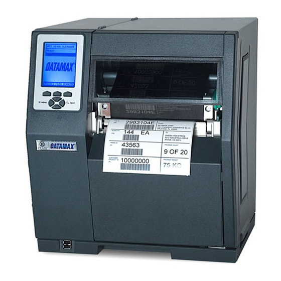
Printer Overview Congratulations on your purchase of a Datamax H-Class printer. The H-Class family of printers (hereinafter referred to as "the printer") takes you into the next era of comprehensive thermal and RFID label printing. Built upon a cast frame and innovative modular design, this printer delivers the most flexible configuration and accurate print quality offered in the industry, while its IntelliSEAQ™... -
Page 10: Media Selection
The following is a limited overview of media characteristics. For complete information and advice regarding your specific application needs, always consult a qualified media specialist or a Datamax Media Representative. Also available is our informative whitepaper, "A Brief Introduction to Media," at www.datamaxcorp.com. - Page 11 • The second setting is PRINT CONTROL / HEAT -- increase this value to darken the image, or reduce the value to lighten the image. • The third setting is PRINT CONTROL / PRINT SPEED -- increase the value to increase throughput (more heat may be required to achieve the desired print contrast), or decrease the value to allow more time and control for energy transfer.
-
Page 13: Printer Connections
Printer Connections Connecting Power The printer will automatically detect then adjust to most applied line voltages. (See Specifications for information regarding the acceptable voltage ranges.) Note: Before connecting the AC Power Cord, ensure that the Power Switch is in the OFF (O) position. -
Page 14: Interface Connections
Interface Connections Host Connections The printer can be connected to your host system via the Ethernet, USB, parallel, and serial ports. Communications are automatically established and set according to the first printer port that receives valid data from the host. Once established, a selectable Host Time-out period must elapse or printer power must be cycled OFF and ON to switch communications to an alternate port. - Page 15 Parallel Connection: The parallel interface supports directional communications. Choose and connect your cabling as follows: • For unidirectional communication, use a Centronics IEEE 1284 cable with a 36-pin male connector. • For bidirectional communication, use an IEEE 1284 Compliant cable with a 36-pin male connector (and supporting host software).
- Page 16 Notes: (1) An "off the shelf" serial cable can be used with Xon/Xoff handshaking. (2) For RS-422/RS-485 operation, a jumper must be moved on the printer's main board. Click here for details. Ethernet Connection: The Internal Ethernet Print Server operates under several menu- selectable modes, as detailed under the NIC ADAPTER section of this manual.
- Page 17 SDIO Slot and USB Host Connections The Secure Digital Input Output (SDIO) Slot and the USB Host Ports accept external memory storage devices for fonts, graphics, label formats, and firmware upgrades. Additionally, the USB Host Ports can accept a USB keyboard for direct inputting of data under certain applications, including Line Mode operation.
- Page 18 • Notes: Before initial use, SDIO Memory Cards and USB Memory Drives must be formatted by the printer, see Modules (in Printer Options) for details. • The SDIO Slot supports SanDisk© SDIO Memory Cards up to 1 GB; SDIO Multi Media Cards, however, cannot be used. When installing an SDIO Card, turn OFF the printer then slide the SDIO Card into the SDIO Slot.
-
Page 19: Ethernet Setup
Ethernet Setup The Print Server makes IP requests at power-up, so before making a network connection to the printer consider how your IP Addressing needs to be assigned. The IP Addressing of the Internal Ethernet Print Server can be configured in one of two ways: >... - Page 20 8. After entering the addresses, press the EXIT button and save your changes when prompted. 9. Turn OFF the printer, connect the Ethernet cable, turn the printer back ON, and then ® install the port and printer driver using the Windows ‘Add a Printer Wizard’;...
- Page 21 Note: Depending upon your server, you may have to wait a minute or two for the Assigned IP Address to appear on the Configuration Label. 7. After the Assigned IP Address has been obtained, proceed to install the port and ®...
- Page 22 Using the HTML Pages The printer has resident HTML (Web) pages that the allow configuration of network and printer settings as well as status queries and diagnostic tests. To configure the Print Server and other internal printer settings, you can access the printer via HTML pages using any Web browser. Screen samples and comment text (outlined in red boxes) are given in the examples that follow.
- Page 23 Network Status page: TCP/IP Configuration page:...
- Page 24 System Settings, Media Settings, and Print Control pages: Many of the printer's internal menu settings can be controlled remotely (without use of the printer's front panel) to adjust many operational settings. For more information on the function of these settings see the corresponding function in the Menu System.
- Page 25 Driver and Port Setup Windows 2000 Driver and Port Installation Start the Windows Make sure that “Add Printer Wizard”. ‘Local Printer’ is The following screen selected and then should appear, click click ‘Next’. ‘Next>’. Select on ‘Create a Click ‘Next’. new port:’...
- Page 26 Browse to the CD-Rom and click “\DRIVERS\Seag ‘Browse’. ull” folder on the CD-ROM, make sure the file “Datamax for 95, 98, me, 2000, and xp.inf” is selected and click ‘OK’. Click ‘OK’. Select your printer from the list and then click ‘Next’.
- Page 27 Windows XP Driver and Port Installation Start the Windows Make sure that “Add Printer Wizard” ‘Local Printer’ is The following screen selected and then should appear, click click ‘Next’. ‘Next>’. Select on ‘Create a Click ‘Next’. new port:’ and then select ‘Standard TCP/IP Port’...
- Page 28 Browse to the CD-Rom and click “\DRIVERS\Seagu ‘Browse’. ll” folder on the CD-ROM, make sure the file “Datamax for 95, 98, me, 2000, and xp.inf” is selected and click ‘OK’. Click ‘OK’. Select the your printer from the list and then click ‘Next’.
-
Page 29: Media Loading
Media Loading Loading Roll Media Load a roll of media into the printer as follows: 1. Rotate the Printhead Latch in a counterclockwise direction then raise the Printhead Assembly. 2. Slide the Media Guide toward you (outward), and then rotate the Media Guide counterclockwise into an UP position. - Page 30 3. Slide a Roll of Media completely onto the Media Hub then route the media through the printer and straight out the front, as shown: 4. Rotate the Media Guide clockwise into a DOWN position then slide the Media Guide inward until it just touches the edge of the media.
- Page 31 5. If loading media for the first time, or if switching media types (e.g., changing from die-cut to reflective stock), adjust the Media Sensor. 6. Lower the Printhead Assembly then rotate the Printhead Latch completely clockwise. Note: If using thermal transfer media, load ribbon into the printer; otherwise, perform a calibration.
-
Page 32: Loading Fan-Fold And Externally Supplied Media
Loading Fan-fold and Externally Supplied Media Load box-fed fan-fold stock and externally supplied rolled media into the printer as follows: 1. Place your media supply parallel to the printer, in a position that does not twist or turn the stock. Note: If loading reflective media, be sure the black marks are facedown as the material enters the printer. -
Page 33: Loading The Internal Rewinder
Loading the Internal Rewinder When equipped with the Internal Rewind option, printed label outputs can be rewound or, with the addition of a Peel and Present option, dispensed automatically for immediate application. If your printer has this feature, follow the instructions below to begin using the option: 1. - Page 34 3. Place the Arcplate on the front of the printer (as shown below) and tighten the Phillips Head Screw to secure it; or, to use the Peel and Present option attach that device. Proceed according to your application: • To rewind labels onto an empty media core, go to Step 4. •...
- Page 35 5. Grasp the end of the hub and, while pulling outward, squeeze the hub together until it collapses then slide Rewind Core Adapter toward the Centerplate until it locks in place.
- Page 36 6. Slide an Empty Media Core (with a 3-inch diameter) onto the Rewind Core Adapter. 7. Slide the Rewind Retainer into the Empty Media Core then close the Locking Lever. 8. With label stock installed as described in Loading Roll Media, repeatedly press the FEED Key until approximately 20 inches (51 cm) of media has been output from the printer.
- Page 37 9. Route the media back into the printer and around the media core, as shown below. Tape the leading edge of the media to the media core. Unloading the Internal Rewinder To unload the Internal Rewinder, open the Locking Lever, remove the Rewind Retainer, and slip the roll of labels (and core) off the Rewind Core Adapter.
- Page 38 Removing the Adapter Core To switch from label rewinding to label peeling, you will need to remove the Rewind Adapter Core, as follows: 1. Remove labels from the Internal Rewinder. 2. Rotate the Rewind Hub so that the Tabs are in a horizontal position, as shown. 3.
-
Page 39: Loading Ribbon
Loading Ribbon Ribbon is required with thermal transfer media. For convenience, the printer can use ‘coated side in’ or ‘coated side out’ ribbon. Load ribbon as follows: Note: Use a ribbon that is slightly wider than your media (and liner, if any) to help protect the printhead from abrasion. - Page 40 2. In the appropriate direction for the ribbon type (CSI or CSO), slide a Roll of Ribbon onto the Ribbon Supply Hub until it rests against the hub’s flange. (Directional arrows near the Ribbon Supply Hub also indicate the correct ribbon route.) Note: The coated side "inked"...
- Page 41 4. Route the ribbon up to then around the Ribbon Take-Up Hub. Wind the ribbon several times, in a clockwise direction, around the Ribbon Take-Up Hub to secure it in place. 5. Lower the Printhead Assembly then rotate the Printhead Latch completely clockwise. 6.
-
Page 43: Printer Operation
Printer Operation Control Panel The Control Panel, an event-driven user interface, is comprised of a graphic display, buttons, and keys. In addition to providing a real-time display of current printer functions, the operation is mode-dependent, allowing the items in the Main Display Area and the functions of the Soft Keys to change as events or selections require. -
Page 44: Windows Driver
When prompted for the driver file, select 'Have Disk' and browse to the following file on the CD-Rom: Windows 95, 98, ME, 2000, and XP: "D:\DRIVERS\Seagull\Datamax for 95, 98, me, 2000, and xp.inf" (Where D: is your CD-Rom drive) Windows NT4.0: "D:\DRIVERS\Seagull\NT4\Datamax for nt 4.0 only.inf"... -
Page 45: Important Notes
Important Notes: The Windows driver functions the same as any other Windows printer. A built in help file is available for complete information on all settings, however there are some important settings that should be observed for trouble free printing. Page Setup Tab: Stock Options Tab: Print Speed &... -
Page 46: Printer Configuration Utility (Dmxconfig)
(USB, Ethernet, ect.) assigned to a Datamax printer driver port. DMXConfig Features: > Allows Real-Time Control/Query of Printer Configuration >... -
Page 47: Menu System
Menu System The User Interface The user interface provides simple menu navigation and access to printer operations, the generation of test labels, and the diagnosis of hardware. Using the Menu, Test, and Navigation Buttons on the Control Panel, you can make these setting changes, print test labels, and perform printer testing. - Page 48 For ease of use, the Menu System is divided into three distinct functional branches: • User Menu accesses basic operational settings; • Advanced Menu accesses the entire range of settings and diagnostics; and, • Test Menu accesses informational and diagnostic label formats, and allows a previously printed label to be reprinted.
-
Page 49: The User Menu
The User Menu The User Menu contains the following selections: • Media Settings • Print Control • Printer Options • System Settings Notes: (1) Except for the menu level selection, menu changes will only become effective (and saved) by selecting ‘Yes’ at the ‘Save Changes’ prompt. (2) Labeling software may, in some cases, override the printer menu settings: to access the entire range of printer settings, enable the Advanced Menu. -
Page 50: The Advanced Menu
The Advanced Menu The Advanced Menu contains the following selections: • Media Settings • Print Control • Printer Options • System Settings • Communications • Diagnostics To enable the Advanced Menu, proceed as follows: 1. Press the MENU BUTTON. 2. Using the UP or the DOWN BUTTON, scroll to SYSTEM SETTINGS then press the ENTER KEY. -
Page 51: The Test Menu
The Test Menu The Test Menu contains the following test and informational label selections: • Print Quality Label • Ribbon Test Label • Test Label • Validation Label • Print Configuration • Print Last Label • User Defined Label These are internally generated labels, printed with pre-selected media type, speed, and heat settings. -
Page 52: Menu Item Listings
Menu Item Listings Media Settings Within the Media Settings branch, the following menu selections are available: • Media Type • Sensor Type • Label Length • Maximum Label Length * • Paper Empty Distance * • Label Width • Ribbon Low Options * •... - Page 53 LABEL LENGTH Determines the length of the label (0 - 99.99 inches) when the SENSOR TYPE is set to CONTINUOUS, where: 04.00 inches Is the Default Setting. MAXIMUM Sets the length of media (0 - 99.99 inches) that the printer will attempt to feed LABEL LENGTH between the sensing of TOF gaps or marks (when the Sensor Type is set to GAP or REFLECTIVE) before a TOF Fault is declared, where:...
- Page 54 EMPTY Establishes the threshold for the empty value (0 - 255), where 000 is the Default SENSOR Setting. LEVEL TRAN SENSOR Establishes the sensitivity of the transmissive sensor (0 - 31), where 15 is the GAIN Default Setting. REFL SENSOR Establishes the sensitivity of the reflective sensor (0 - 31), where 15 is the Default GAIN Setting.
-
Page 55: Print Control
Print Control Within the Print Control branch, the following menu selections are available: • Heat • Print Speed • Feed Speed • Reverse Speed * • Slew Speed * • Row Offset • Column Offset • Present Distance • Custom Adjustments * Note: Items denoted with an asterisk (*) are only accessible through the Advanced Menu. - Page 56 ROW OFFSET Shifts the vertical start of print position (0 - 99.99 inches) on the label, where: 00.00 inches Is the Default Setting. COLUMN Shifts the HORIZONTAL, left-justified start of print position to the right (0-99.99 OFFSET inches), without shifting the LABEL WIDTH termination point to the right, where: 00.00 inches Is the Default Setting.
-
Page 57: Printer Options
Printer Options Within the Printer Options branch, the following menu selections are available: • Modules • Present Sensor • Cutter • Scanner • RFID • GPIO Port • Rewinder Note: Items denoted with an asterisk (*) are only accessible through the Advanced Menu; also, certain selections will appear only when equipped with that option. - Page 58 PROCESS Selects from the list of external extensions and, as noted, converts then stores them FILE * with internal file extensions. External Action Converted Extension (Internal) Extension BMP, PCX, Converts the file into an internal format, where IMG, & F7B the result is stored in Module G.
- Page 59 PRESENT Controls the "on-demand" dispensation of labels (by inhibiting further label printing SENSOR until a previously printed label is removed) when the printer is equipped with the Present Sensor or Peel and Present option, where: MODE Sets the option detection and response of the printer: AUTO Automatically detects, enables the sensor, and sets the label stop location for the option;...
- Page 60 REDUNDANCY Ensures integrity by setting the number of consecutive, identical decodes that are LEVEL * required for the bar code to be considered readable. For example, if set to three times, the bar code will not pass until the same values have been decoded three times in succession.
- Page 61 UHF SETTINGS Sets UHF tag parameters: TAG TYPE Sets the tag type: EPC 0 EPC 0+ MATRICS EPC 0+ IMPINJ EPC 1 UCODE EPC 1.19 EM 4022/1222 GEN 2 TAG DATA Sets the tag data size: SIZE 96-BIT 64-BIT POWER ADJUST KILL CODE B3 B2 B1 B0...
- Page 62 END OF PRINT * Sets the type of output signal that is generated to indicate the End of Print (EOP) process, where: LOW PULSE Outputs a low pulse (approximately 30 milliseconds long) following printing. HIGH PULSE Outputs a high pulse (approximately 30 milliseconds long) following printing. ACTIVE LOW Outputs a logic ‘low’...
-
Page 63: System Settings
System Settings Within the System Settings branch, the following menu selections are available: • Menu Mode • Configuration File • Internal Module D * • Default Module * • Scaleable Font Cache * • Single Byte Symbols * • Double Byte Symbols * •... - Page 64 The menu selections are defined as follows: DISPLAYED ITEM DESCRIPTION ITEM MENU MODE Selects which menu level is accessed when entering the menu system, where: User Menu Accesses the limited function menu that contains basic controls. (Default Setting) Advanced Accesses the full function menu that contains all controls, settings, and Menu diagnostics.
- Page 65 SINGLE BYTE SYMBOLS Selects which code page is used to print single byte fonts, unless otherwise specified, where: ARABIC-8 CYRILLIC ISO 60: DAN/NOR DESKTOP ITC ZAPF DINGBAT/100 ITC ZAPF DINGBAT/200 ITC ZAPF DINGBAT/300 PS ITC ZAPF DINGBAT ISO 8859/1 LATIN 1 ISO 8859/2 LATIN 2 ISO 8859/5 LATIN 5 ISO 8859/10 LATIN 6...
- Page 66 PTXT3000 NON-UGL, PI FONT ROMAN-8 ROMAN-9 ISO 17: SPANISH ISO 11: SWEDISH SYMBOL TURKISH-8 PS TEXT UTF-8 ISO 4: UK ISO 6: ASCII VENTURA INTERNATIONAL VENTURA US VENTURA MATH WINDOWS 3.1 LATIN 1 WINDOWS LATIN/ARABIC AGFA TIDBITS WINDOWS 3.1 LATIN 2 WINDOWS LATIN/GREEK WINDOWS 3.1 LATIN 5 WINDOWS...
- Page 67 Displays and controls various internal counters, where: MEDIA COUNTERS ABSOLUTE Shows the total number of inches printed and the date the counter was set; COUNTER this counter is not resettable. PRINTHEAD Shows the total number of inches printed; this counter is not user COUNTER resettable.
- Page 68 APPLICATION Displays the version level, version number, and date of the application VERSION firmware. BOOT LOADER Displays the version level and date of the boot loader. UPGRADE Upgrades the software feature level of the printer. (An authorization code PRINTER CODE is required -- use the UP and DOWN Buttons to enter the alphanumeric authorization code, use the LEFT and RIGHT Buttons to position the cursor, and the ENTER Key to enter the number).
- Page 69 IMAGING Determines the process used to format labels, a selection that can affect MODE throughput and the accuracy of time-stamping, where: MULTIPLE Images multiple labels as memory permits, achieving the fastest throughput. LABEL If time-stamping labels, however, the indicated time will reflect the moment of imaging rather than the actual print time.
- Page 70 INPUT MODE Defines the type of processing that will occur when data is received, where: Datamax programming language processing will be used. (Default Setting) LINE Line Mode processing will be used, where data terminated by a carriage return will be extracted and inserted into a template for printing.
- Page 71 COLUMN Allows the dots per inch in the column to be adjusted (153 - 203 dots), so that EMULATION numbers smaller than the printhead resolution shrink the image from right to left, where: 203 Dots Is the Default Setting. Allows the number of dots per inch in the row to be adjusted (103 - 303), so EMULATION that numbers smaller than the printhead resolution enlarge the height of the printed output and numbers larger shrink it, where:...
- Page 72 LABEL STORE Determines the command recall level used when retrieving stored label formats, where: STATE & Recalls the printer state (that is, the heat setting, speed settings, etc.) and the FIELDS label-formatting commands of the stored label. (Default Setting) FIELDS Recalls only the label-formatting commands of the stored label.
- Page 73 VOID Sets the distance (0.10 - 2.00 inches) to retract the faulted label to print a DISTANCE ‘VOID’ on its trailing edge; this distance indirectly establishes the font size of the void message. 0.50 Is the Default Setting. RETRY Establishes the number of times (0 - 3) a label reprinting attempt will be COUNT made.
- Page 74 Communications Within the Communications branch, the following menu selections are available: • Serial Port A • Serial Port C • Serial Port D • Parallel Port A • NIC Adapter • Host Settings The menu selections are defined as follows: DISPLAYED ITEM ITEM DESCRIPTION SERIAL PORT A Controls the RS-232 communications settings for Serial Port A, as...
- Page 75 SERIAL PORT C When equipped with a GPIO Card, this controls the RS-232 communications settings for the COM C (J4) port, as follows: BAUD RATE Sets the serial communication rate: 1200 BPS 1200 bits per second 2400 BPS 2400 bits per second 4800 BPS 4800 bits per second 9600 BPS...
- Page 76 PARITY Sets word parity, where: NONE Parity is not used. (Default Setting) Odd parity is used. EVEN Even parity is used. DATA BITS Sets word length, where: A seven bit word is used. An eight bit word is used. (Default Setting) Sets the number of stop bits, where: STOP BITS One stop bit is used.
- Page 77 IP DISCOVERY Sets the address discovery method, where: ENABLED Upon start-up, the card will broadcast into the network to receive an addresses from the responsible server. Manual modifications to IP Address, Subnet Mask, or Gateway Address is not allowed; and, if no server is found, the specified static value will be used.
- Page 78 Allows data containing invalid ESC control code sequences to be SEQUENCES processed, where: ENABLED Normal command processing occurs. (Default Setting) DISABLED ESC sequences are ignored during data processing (since some systems send a “banner” to the printer). Bitmapped font downloads are disabled in this mode.
- Page 79 OPTION Allows feedback characters from an optional device to be returned to the FEEDBACK host device, in the format of: <A;B;C;D;E;F>[CR] Where: Is the device type: R = RFID; and, S = Linear Scanner Is the resulting status: C = entire label complete; F = faulted (failed) label;...
- Page 80 Diagnostics Within the Diagnostics branch, the following menu selections are available: • Hex Dump Mode • Options Testing • Print Test Rate (min) • Sensor Readings • Ribbon Sensor Limits • iPH Report The menu selections are defined as follows: DISPLAYED ITEM ITEM DESCRIPTION HEX DUMP MODE Determines how the printer handles the data received from a host, where: ENABLE...
- Page 81 TEST GPIO Performs a functional test of the General Purpose Input Output interface, where: MONITOR GPIO Input logic values are displayed for Start Of Print, Feed, Pause, Reprint, INPUT and the six unassigned input lines. (Note that unconnected lines may display a zero or one value.) The values below are given as examples only: SOP FEED PAUSE REPRINT...
- Page 82 PRINT SIGNAL Prints a reference label (see sample below) containing GPIO signal INFO names, pin and port assignments, programmed settings, and current signal states. TEST SCANNER Performs a functional test of the Linear Scanner, where: ALIGNMENT Enters “multiple read mode,” allowing bar codes to be continuously TEST scanned.
- Page 83 SENSOR Displays the values (0 - 255, see sample below) read from different READINGS sensors within the printer, where: THR TRAN RIBM 24V HD RANK 003 255 THR = Printhead thermistor sensor; TRAN = Transmissive (gap) media sensor (TRAN is replaced with REFL when the SENSOR TYPE is set to ‘reflective’);...
- Page 84 iPH REPORT Displays the IntelliSEAQ™ printhead report, which includes the printer key and printhead serial number, the installation date, and the times and dates of printhead maintenance, where: VIEW Outputs the data to the front panel display. PRINT Prints a reference label in the following format: iPH REPORT TUE 12:44PM 23MAY2006...
-
Page 85: Maintenance And Adjustments
Maintenance and Adjustments Cleaning Intervals The following list and table detail the recommended items, techniques, and schedules to help you safely and effectively maintain your printer. • Isopropyl alcohol • Cotton swabs • A clean, lint-free cloth • Soft-bristle brush •... - Page 86 Area / Method Interval Item) Peel/Tear Using a cotton swab As needed dampened with solvent*, remove all adhesive build- up on the tear edge, and using a soft-bristle brush remove all paper debris on the component. Media Using compressed air or a Monthly Sensor soft-bristled brush,wipe the...
-
Page 87: Printhead Cleaning
Printhead Cleaning If print quality declines (symptoms can include unreadable bar codes, or streaks through the text and graphics), the typical cause is debris build-up on the printhead. Furthermore, if not removed, this build-up may lead to premature dot failure. Clean the printhead every time a roll of ribbon has been used. - Page 88 Cotton Swab Procedure (for printers using direct thermal media, or thermal transfer media and wax ribbon): 1. Perform the "Preliminary Cleaning Steps", as described above. 2. Turn OFF the power switch and unplug the printer. Using a Cotton Swab moistened (not soaked) with isopropyl alcohol, gently clean the entire printhead surface, until all build- up is removed.
- Page 89 Cleaning Card Procedure (for printers using direct thermal media, or thermal transfer media and wax ribbon; also, use the following procedure if symptoms continue after the Cotton Swab Procedure has been tried): 1. Perform the "Preliminary Cleaning Steps", as described above. 2.
- Page 90 Cleaning Film Procedure (for printers using thermal transfer media and a resin ribbon, or for printers that typically use a Heat Value of 22 or higher; also use this procedure if symptoms continue after the previous methods have been tried): 1.
-
Page 91: Printhead Pressure Adjustment
Printhead Pressure Adjustment To accommodate a variety of media types, the pressure applied by the printhead assembly is adjustable. Factory set to work with most media types, the Printhead Pressure Adjustment should only be performed after attempting to improve print quality through the use of the print quality controls. -
Page 92: Printhead Leveling Adjustment
Printhead Leveling Adjustment When printing on less than full width media, adjust the Printhead Leveling Cam (shown below) to evenly distribute the pressure applied to narrow label stock. Notes: (1) When changing to a different width of label, always readjust the Leveling Cam. (2) Under-adjustment of the Leveling Cam can cause problems that include ribbon wrinkling, label tracking, and excessive platen roller and printhead wear. - Page 93 2. While observing the printing, rotate the Printhead Leveling Cam counter-clockwise to an over-adjusted position so that the output image fades across the label, as shown in Example 1: Example 1 – Over Adjustment 3. Rotate the Printhead Leveling Cam clockwise, one click at a time, until the output image is complete and printed with even contrast across the label, as shown in Example 2: Example 2 –...
-
Page 94: Media Sensor Adjustment
Media Sensor Adjustment The Media Sensor (attached to the Slide Tab, as shown below) must be selected and positioned to detect the labels. Set and adjust the Media Sensor as follows: 1. Enter the Menu, select the appropriate Sensor Type for the media you are using, then save your changes and exit the menu. - Page 95 3. Grasp the Slide Tab and as outlined the table below, depending on the Media , move it to the recommended Position. Media Sensor Selection and Position Sensor Type Media Position Die-cut Centered under the label Notched Centered under the notch Centered under the black Reflective Reflective...
-
Page 96: Printhead Removal And Replacement
(2) Printheads are fragile devices: use extreme care during handling and never use a sharp object on the printing surface. (3) If you have questions, contact a qualified technician or Datamax Technical Support before proceeding. 1. Touch a bare metal printer surface (e.g., the frame) to discharge any static electricity that may be present on your body then turn OFF the power switch and unplug the printer. - Page 97 4. Unlock the Printhead Assembly then carefully raise the assembly. Grasp the printhead, disconnect the two cables, and remove the printhead. 5. Position the new Printhead under the Printhead Assembly and connect the previously removed cables. 6. Place the Printhead onto the locating pins under the Printhead Assembly and then secure it in position with the Printhead Mounting Screw.
-
Page 98: Sensor Calibration
Sensor Calibration Calibration ensures consistent label detection and print positioning. There are three ways to calibrate the printer; each differs according to the level of calibration required for the media being used: • Quick Calibration -- Use this method for most media types (see note below) during initial printer set-up or after changing the media type. - Page 99 Quick Calibration Quick Calibration should be performed as part of your media loading routine to fine-tune the sensing parameters. Notes: (1) This calibration is not necessary when using continuous stock. (2) Media containing large gaps may require a change in the PAPER OUT DISTANCE before proceeding.
-
Page 100: Standard Calibration
Standard Calibration During this process, the printhead assembly can be raised for visual access. In addition, active sensor readings can be used to further determine the best position for small, position-critical TOF notches or marks. Three readings are required: • Empty: A measurement taken with no media over the sensor. - Page 101 Displayed Step Action Comment(s) Message Proceed according to the kind of media being calibrated: • Die-Cut Media -- This sets the gap (or mark) value - Remove at least six where ‘yyy’ is a numerical value inches (15 cm) of the representing the sensor reading for For die-cut media: beginning label material...
- Page 102 Displayed Step Action Comment(s) Message For die-cut media: GAP MODE CALIBRATION COMPLETE Calibration was successful. - or, for reflective media: Note: If ‘Warning Low Backing’ is Observe the display for the displayed (a typical message when REFLECTIVE MODE outcome of the calibration then calibrating notched media or die-cut CALIBRATION press the ESC Key.
-
Page 103: Advanced Entry Calibration
Advanced Entry Calibration ADVANCED ENTRY should only be used when the Standard Calibration method has failed. To facilitate the placement of the media sensor, the printhead assembly can be raised. During this procedure, sampled readings will be used to manually establish the best gain algorithm for sensing the media. - Page 104 Displayed Step Action Comment(s) Message Create a table with 32 rows (one for each of the Gain Numbers that will be tested) and four columns with headings similar to the one shown below. Use the UP, DOWN, LEFT, and RIGHT Buttons to set the Gain Number to 00 and then press the The YYY value represents the current ENTER Key.
- Page 105 Displayed Step Action Comment(s) Message Use the UP, DOWN, LEFT, and RIGHT Buttons to set the Gain Number to 00 and then press the ENTER Key. Record the reading as a TOF Value for Gain Number 00 in the table. TRAN SENSOR GAIN Increment the Gain Number and...
- Page 106 Displayed Step Action Comment(s) Message TRAN SENSOR GAIN Use the UP and DOWN Buttons to set the Gain Number determined in (0 - This example uses Gain Number 08. the previous step. Press the ENTER Key to enable the setting. Complete a table using new measurements, as follows: (A) Raise the Printhead Assembly.
- Page 107 Displayed Step Action Comment(s) Message Press the ESC Key. Use the DOWN Button to scroll to GAP SENSOR LEVEL (or, if using GAP SENSOR reflective media, MARK SENSOR LEVEL LEVEL) and then press the ENTER Key. (0 - 255) 0 3 5 Use the UP, DOWN, LEFT, and RIGHT Buttons to set the Gap (or Mark) value determined in Step 11...
-
Page 108: Resetting The Printer
Resetting the Printer Depending upon the method used and the result desired, there are three different reset levels: • Soft Reset -- Clears the printer of any temporary host settings. To execute a Soft Reset, press and hold the CANCEL Key for approximately four seconds. •... -
Page 109: Updating Firmware
Updating Firmware Stored in Flash memory, the operating system can be easily and quickly updated as follows: 1. Identify the desired version of firmware for your printer model from our web site and then download that file onto your computer’s hard drive. 2. - Page 110 Displayed Message Description, Possible Causes and Solutions ERROR WRITING The program could not successfully be written into Flash memory. FLASH Defective Flash memory is a possible cause. Try the download again; however, if the problem continues call for service. HARDWARE The Application Firmware downloaded is not compatible with the Main MISMATCH Logic Card, is for a different model printer, or is not supported by the...
-
Page 111: Boot Loader Downloads
Boot Loader Downloads Available updates for the Boot Loader program can be found at ftp://ftp.datamaxcorp.com. Before performing this update, identify the printer’s current Boot Loader version by printing a Configuration Label and comparing the installed version to those available from the FTP site. Download the desired version onto your computer’s hard drive then follow the steps below to update the Boot Loader program: If power is lost while ‘Upgrading Software’... - Page 112 Step Displayed Operator Action Comments Message H4210.173 The printer has automatically reset. 7/01/2005 READY The new application is now running. Note: If ‘Uncalibrated’ is displayed, the printer must be calibrated. Notes: If the procedure above fails to put the printer into boot mode, use this method: (A) Turn OFF the power switch.
-
Page 113: Font Downloads
Font Downloads Font files (KANJI, HANGUL and CHINESE) can be downloaded to the printer and stored in a module. Font files are identified by part number, and are protected by lock bits. Lock bits can be individually unlocked by inputting a printer-unique 6-digit code via the front panel. Note: The CGTIMES font is resident;... - Page 114 Displayed Description, Possible Causes and Solutions Message SYSTEM FAULT Insufficient memory space for font file exists in the destination module. Try selecting a different destination module and perform the download again. ACCESS A font file of the same name already exists in memory. DENIED FILE EXISTS ACCESS...
-
Page 115: Prompts, Messages, And Troubleshooting Tips
("If experiencing this problem"), and then apply the suggestions to find a resolution ("Try this solution"). If at any time you have questions or if the problem persists, contact a qualified technician or Datamax Technical Support. - Page 116 If experiencing Try this solution... this problem... • Missing information Check the label format for character or image placement outside in the printed label: the dimensions of the label; all row/column values must allow enough space for the height/length of the characters and bar codes to be printed within the format size.
- Page 117 If experiencing Try this solution... this problem... Nothing is printing Examine the used ribbon for traces of an image, then proceed using thermal accordingly: transfer media • (labels advance If an image is on the used ribbon, verify that the ribbon was normally, but no properly loaded.
-
Page 118: Alert Prompts And Condition Messages
Alert Prompts and Condition Messages Alert Prompts appear when an operator action is required, while Condition Messages are generated to indicate an operational state of the printer. Prompts and Condition Messages Displayed Description Cause(s) Message You are attempting to enter a secured menu, ACCESS DENIED Your entry is refused. - Page 119 Displayed Description Cause(s) Message This is the normal The printer is waiting, ready to receive label operating mode of the READY formats, downloads, etc. printer. REMOVE In order to proceed, The TEST Button was pressed and held or RIBBON ribbon must be removed CLEAN HEAD NOW was selected with ribbon PRESS ANY KEY and then a key pressed.
-
Page 120: Warning And Fault Messages
Warning and Fault Messages During normal operation, printer functions are internally monitored. If the potential for a problem is detected, a corresponding message and icon will be displayed to alert you to this condition. There are two tiers of problem messages: •... - Page 121 Use the table below to locate the message that was displayed by the printer, follow the row over to find a description of the problem, and then a possible solution. If you have questions, contact a qualified technician or Datamax Technical Support. Printer Warning Messages Displayed...
- Page 122 Displayed Description Possible Solution(s) Message HEAD NEEDS The scheduled printhead Clean the printhead; see Printhead Cleaning CLEANING cleaning distance has been for cleaning details. reached. To change this programmable setting, enter Advanced Menu / Media Settings / Printhead Cleaning Menu. HOST The host has changed the To save these changes, send a host reset...
- Page 123 Displayed Description Possible Solution(s) Message RIBBON LOW The ribbon supply is almost Load a new roll of ribbon soon. exhausted. RTC RAM The printer was unable to Possible faulty Main Logic Card. Retry your FAILURE save settings in permanent save. If the condition persists, call for memory.
- Page 124 Use the table below to locate the message being displayed by the printer, follow the row over to find a description of the problem, and then a possible solution. If you have questions, contact a qualified technician or Datamax Technical Support. Printer Fault Messages...
- Page 125 Displayed Description Possible Solution(s) Message HEAD The scheduled printhead See Printhead Cleaning for cleaning details. CLEANING cleaning has been exceeded FAULT by an amount equal to three To change the programmed setting, enter times the pre-programmed the Advanced Menu then go to Media distance.
- Page 126 Displayed Description Possible Solution(s) Message REFLECTIVE Consistently high sensor Press any key to continue. Ensure that MODE readings were detected. media was removed from the media sensor FAULTY during the appropriate calibration steps; also SENSOR ensure that no labels are stuck in the media sensor.
- Page 127 Displayed Description Possible Solution(s) Message TEMPERATURE The printer has shutdown to Make sure the printer is placed within a FAULT allow the printhead acceptable environment. Turn OFF the temperature to cool. printer and wait until the printhead cools sufficiently to prevent permanent damage. •...
-
Page 128: Hex Dump Mode
To decode the data strings, the Class Series Programmer’s Manual is an essential reference. (Note that some software programs use bit-mapping to construct the label, making diagnosis difficult. Contact Datamax Technical Support with any questions.) To place the printer into Hex Dump Mode, press the MENU Button, select DIAGNOSTICS, go to HEX DUMP MODE, select ENABLE, and press the ENTER Key. -
Page 129: Appendix A - Features And Printer Specifications
Appendix A - Features and Printer Specifications Features H-Class printers are available in the following configurations: H-4212X: Print Speed - 12 IPS; Resolution 203 DPI H-4310X: Print Speed - 10 IPS; Resolution 300 DPI Standard Features Mechanical Features Direct-Thermal printing Easy loading Media Tear Bar Three-inch Media Hub... -
Page 130: Optional Features
Software Features Continued…. Internal Configuration Label Text, bar code, graphic, and image printing capabilities Factory default configuration restorable Resident multiple setup store and restore capability Time stamp at print capability Label retract control after print Ribbon low detection and warning Power-up diagnostics Resident option hardware diagnostics Diagnostic display and modes... -
Page 131: Option Installation
> Simplified Chinese GB Scalable font > Korean Hangul font Option Installation The following table lists the available options and the recommended qualification level of the installer. For detailed information concerning a specific option, contact your dealer or Datamax Technical Support. Option Installation Requirement Level... -
Page 132: Printer Specifications
Printer Specifications Mechanical Width 12.51” (317.8mm) Depth 18.83” (478.3mm) Height 16.37” (415.8mm) Weight 46.6 lbs (21.1kg) Operating 32° to 100° F (0° to 38° C) Temperature 10% − 95% non-condensing Humidity AC Input 90 – 132 or 180 – 264 VAC @ 47–63 Hz, auto-ranging. Voltage Printing Print Method... - Page 133 Media Media Types Roll-Fed, Die-Cut, Continuous, Fan-Fold Media Width 1 – 4.65" (25 – 118 mm) Range Max Print 4.094” (104mm); H-4212X Width 4.161" (105.7mm); H-4310X Print Length .25 - 99" (6 - 2500 mm) Range Media 0.0025 - 0.010" (0.06 - 0.25 mm) Thickness Range Media Supply...
- Page 134 These supplies are specially formulated for use in our printers; use of non-Datamax supplies may affect the print quality, performance, and life of the printer or its components. For a current list of approved media, please contact a Media Representative at (407) 523-5650.
-
Page 135: Appendix B - Embedded Fonts And Barcodes
Appendix B - Embedded Fonts and Barcodes Embedded Fonts All character fonts available with the printer are described in this section. Each font has a name associated with it for use in programming. Human-readable fonts have numeric names. Fonts 0 through 8 use the slash zero (Ø) conventions for distinguishing between the zero and the alphabetic O. - Page 136 Font 2 138-character alphanumeric, upper and lower case. Font 3 62-character alphanumeric, uppercase. Font 4 62-character Font 5 62-character alphanumeric, uppercase. alphanumeric, uppercase. Font 6 62-character alphanumeric, uppercase. Font 7 OCR-A, size I. Font 8 OCR-B, size III.
- Page 137 Font 9 Internal Triumvirate font. Internal Triumvirate font. The number in the bar code height field sets the point sizes. Larger point sizes can be obtained by increasing the height and width multipliers, (see the Programmer's Manual for more information).
-
Page 138: Embedded Bar Codes
Embedded Bar Codes Bar Code fonts have alpha names (left column in the table below). Uppercase alpha names will print bar codes with human-readable interpretations. Lowercase alpha names will print bar codes only. The table is followed by visual samples. Barcode Type Length... - Page 139 Barcode A Code 39 Barcode B UPC-A (regular) Barcode C UPC-E (zero suppression) Barcode D Interleaved 2 of 5 Barcode E Code 128 Barcode F EAN-13 Barcode G EAN-8 Barcode H Health Industry Bar Code (Code 39 Mod and 43 checksum) Barcode I Codabar Barcode J Interleaved 2 of 5 w/module 10 checksum...
- Page 140 Barcode K Plessey Barcode L ITF SCC-14/ I 2 of 5 Shipping Container Code Barcode M 2 Digit UPC addendum Barcode N 5 Digit UPC addendum Barcode O Code 93 Barcode p Postnet Barcode Q SSCC-18/Serial Shipping Container Code Barcode R UCC/EAN Code 128 KMART NON EDI Barcode S UCC/EAN 128 Random Weight...
- Page 141 Barcode T Telepen Barcode u UPS MaxiCode Barcode v FIM Barcode z PDF417 Bar Code W1c: DataMatrix Bar Code W1d: QR Code Bar Code W1f: Aztec Bar Code W1k: RSS (Reduced Space Symbology) Bar Code W1z: MicroPDF417...
-
Page 143: Appendix C - Module File Definitions
Downloadable plugin file containing a group of hidden encrypted or normal Datamax specific format. files. The file is generated via “img2dl” and “bfcart” utilities. Downloadable compressed firmware Datamax specific format. upgrade download file. 7-bit Datamax image load file. Datamax specific format. -
Page 145: Appendix D - Multi-Language Downloads
Appendix D - Multi-Language Downloads Different languages and / or Datamax-provided translations can be downloaded to replace the printer's standard English menu system. The menu language is constructed via a Microsoft® Excel spreadsheet that defines the system dictionary. To make a change to the language, the user adds a new language column (or modifies an existing column in the spreadsheet), clicks on the ‘Generate DPL file(s)’... - Page 146 Create a Menu Language by following these steps: 1. Invoke Excel and open the Common.xls file. Excel opens the file and the following screen appears: 2. Click the “Enable Macro” box. The following table appears: 3. Click On Column J and enter your new language, or modify an existing one. Some tips on this process: A) Message Size –...
- Page 147 B) Two Line Messages – Some of the message are displayed as two lines. These are indicated in the comment fields. C) Comments – This field can be modified with no effect. 4. When editing has been completed, highlight all of the columns you desire to create by pressing the letter above the column (more than one language may be selected).
- Page 148 An error has occurred if the menu system displays the new language selection, but all the displayed messages remain in English. In this case, re-check your process or contact Datamax Technical Support (be prepared to provide the Common.xls and DPL download files created).
- Page 149 To restore the factory generated EFIGS image, download the file *832296.01A to the printer. This file is located on the Datamax FTP site. The letter at the end of the file name (e.g., A) specifies the revision. The latest revision will be available on the FTP site.
-
Page 150: Appendix E - Saving A Configuration File
Appendix E - Saving a Configuration File The printer can save and restore printer settings through the use of configuration files; here are some highlights and restrictions: • Configuration files eliminate the need to make special repeated printer setups. Once saved to a file, job changeovers become faster and easier with these programmed presets. - Page 151 The following example saves a manually-entered setup (an application that required a special media calibration) as a configuration file: Step Action Displayed Message Comment With the printer set for SELECT FUNCTION You are entering the Menu System. the configuration to be saved, press the any Navigation Button.
-
Page 153: Glossary
Glossary alphanumeric Consisting of alphabetic, numeric, punctuation and other symbols. backing material The silicon-coated paper carrier material to which labels with adhesive backing are affixed. Also referred to as “liner”. bar code A representation of alphanumeric information in a pattern of machine-readable marks. - Page 154 Also referred to as “resolution”. DPL (Datamax Programming Language) programming commands used specifically for control of and label production in Datamax printers. A complete listing of commands can be found in the Programmer’s Manual.
- Page 155 media sensor An electronic device equipped with photosensors to detect media and the top of form on die-cut, notched or reflective media. MMPS (millimeters per second) Metric measurement of printer speeds. notched stock Media, typically tag stock, with holes or notches in the material that is used to signal the top of form.
-
Page 157: Warranty Statement
H-Class™ InteliSEAQ™ thermal printhead. This warranty is valid only if Datamax-approved thermal label media is used, as defined in the then current Datamax list of approved thermal/thermal transfer media, a copy of which is available from Datamax. Failure to use Datamax-approved media is justification for invalidation of this thermal printhead warranty. -
Page 158: Limitation Of Liability
In no event shall Datamax be liable to the purchaser for any damages resulting from or related to any failure or delay of Datamax in the delivery or installation of the computer hardware, supplies or software or in the performance of any services. -
Page 159: Contact Datamax
Contact Datamax Datamax Technical Support We can help! If you are having problems with a Datamax product, please do not hesitate to contact us. Our Technical Support Specialists are available to provide solutions before, during, and after the sale. Please choose a location nearest you:...