Datamax M-Class Mark II Maintenance Manual
Printers
Hide thumbs
Also See for M-Class Mark II:
- Operator's manual (100 pages) ,
- Manual (10 pages) ,
- Quick start manual (8 pages)
Table of Contents
Advertisement
Quick Links
Advertisement
Chapters
Table of Contents

Related Manuals for Datamax M-Class Mark II


Summary of Contents for Datamax M-Class Mark II
- Page 1 M-Class Mark II Maintenance Manual...
-
Page 2: Copyright Information
Copyright Information: CG Triumvirate is a trademark of Agfa Corporation. CG Times based upon Times New Roman under license from the Monotype Corporation. Windows is a registered trademark of the Microsoft Corporation. All other brand and product names are trademarks, service marks, registered trademarks, or registered service marks of their respective companies. - Page 3 Contents Overview Adjustments and Maintenance Troubleshooting Removal and Replacement...
- Page 5 Overview Introduction ..................1 About this Printer ................. 2...
- Page 7 This manual, which primarily includes technical information relating to the electrical and mechanical components, is intended for use by qualified service personnel in the maintenance and repair of M-Class Mark II printers. For related information, refer to the following documents, available for download at http://www.datamax-oneil.com/...
-
Page 8: About This Printer
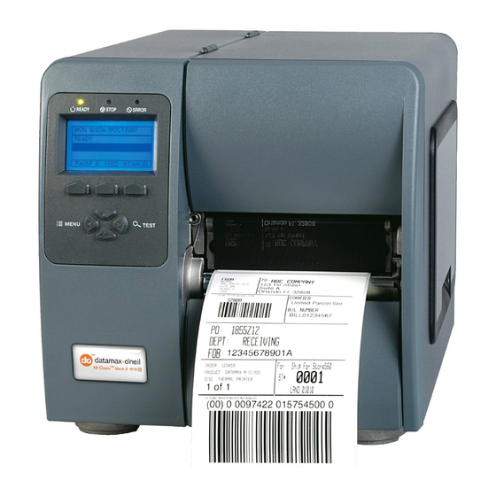
Overview 1.1 About this Printer The following drawing illustrates the basic exterior components and controls of the printer. The model number can be found on the Serial Tag affixed to the rear of the unit. Use this model number when referencing specific information within this manual. (Because optional items are not present on all models, certain printer configurations may not appear in some of the illustrations in this manual.) Access Cover... -
Page 9: Table Of Contents
Adjustments and Maintenance Introduction ..................1 Maintenance ..................1 2.1.1 Cleaning the Printhead ..............2 2.1.1.1 Cotton Swab Procedure ..........3 2.1.1.2 Cleaning Card Procedure ..........4 2.1.1.3 Cleaning Film Procedure ..........5 2.1.2 Cleaning the Media Sensor ............6 2.1.3 Cleaning the Platen .............. - Page 10 Ribbon Path Alignment ............... 23 Darkness Adjustment ................. 26 Downloading Firmware and Fonts ............26 Resetting the Printer ................27 2.9.1 Non-Display Models..............27 2.9.2 Display-Equipped Models ............27 2.10 Printhead Voltage Adjustment.............. 28...
-
Page 11: Adjustments And Maintenance
Adjustments and Maintenance 2.0 Introduction This section covers maintenance and alignment procedures. 2.1 Maintenance Recommended items, techniques, and schedules to help you safely and effectively maintain the printer are detailed below. Keep the following items on hand to clean the printer: Isopropyl alcohol Soapy water/mild detergent •... -
Page 12: Cleaning The Printhead
Adjustments and Maintenance 2.1.1 Cleaning the Printhead NEVER use a sharp object to clean the Printhead; damage can result. CAUTION If print quality declines (symptoms can include non-compliant bar codes, print dropouts, streaks on the label), the typical cause is debris build-up on the printhead. Furthermore, if the build-up is not removed it may lead to element failure, greatly reducing the life of the printhead. -
Page 13: Cotton Swab Procedure
Adjustments and Maintenance 2.1.1.1 Cotton Swab Procedure This procedure is recommended if using direct thermal media, or thermal transfer media with a wax ribbon. 1. Perform the Preliminary Cleaning Steps, as described in Section 2.1.1. 2. Turn OFF and unplug the printer. Using a Cotton Swab moistened (not soaked) with isopropyl alcohol, gently clean the entire Printhead surface, paying special attention to the Burn Line, until all build-up is removed. -
Page 14: Cleaning Card Procedure
Adjustments and Maintenance 2.1.1.2 Cleaning Card Procedure This procedure is recommended for printers using direct thermal media, or thermal transfer media and a wax-based ribbon. Also use this procedure if symptoms continue after the Cotton Swab Procedure (Section 2.1.1.1) has been tried. 1. -
Page 15: Cleaning Film Procedure
Adjustments and Maintenance 2.1.1.3 Cleaning Film Procedure This procedure is recommended for printers using a resin ribbon with thermal transfer media, or for printers that typically use a Heat Value of 22 or higher. Also use this procedure if symptoms continue after the previous cleaning methods have been tried. 1. -
Page 16: Cleaning The Media Sensor
Adjustments and Maintenance 2.1.2 Cleaning the Media Sensor If paper dust or debris accumulates in the Media Sensor, it can affect label detection. To prevent problems, clean as follows: 1. Turn OFF and unplug the printer. Raise the cover. 2. Unlock and raise the Printhead Assembly. Remove any media. 3. -
Page 17: Cleaning The Ribbon Path
Adjustments and Maintenance 1. Turn OFF the Power Switch and unplug the power cord from the AC Receptacle. 2. Raise the Cover. Unlock and raise the Printhead Assembly. 3. Remove media and ribbon. 4. Using a Cotton Swab (or lint-free cloth) dampened with isopropyl alcohol, wipe the Platen clean. - Page 18 Adjustments and Maintenance 3. Using a Cotton Swab (or lint-free cloth) dampened with isopropyl alcohol, wipe the Ribbon Idler and Ribbon Post clean. 4. Using a Cotton Swab (or lint-free cloth) dampened with isopropyl alcohol, wipe the Ribbon Shield clean. Allow to dry.
-
Page 19: Media Sensor Calibration
Adjustments and Maintenance 2.2 Media Sensor Calibration This printer can use many different media compositions, configurations and colors. In addition to adjusting the Media Sensor and selecting the SENSOR TYPE, to ensure that each label is detected correctly and reliably, calibration is required. Depending upon the printer type, there are different calibration methods. -
Page 20: Manual Calibration
Adjustments and Maintenance 5. Simultaneously press PAUSE and CANCEL briefly. Wait until the STOP Light goes OFF. The printer is ready for operation. 2.2.1.2 Manual Calibration Manual Calibration should be used if Automatic Calibration fails, or in cases where sensing problems continue to occur. -
Page 21: Calibrating Display-Equipped Models
Adjustments and Maintenance 8. Install media. Test the calibration by pressing FEED. A label should feed from the printer. Press CANCEL. A Test Label should be produced. Note: To discard calibration changes and revert to the previous settings, turn OFF the ... -
Page 22: Standard Calibration
Adjustments and Maintenance Calibration Hints: In certain cases, the printer may have trouble differentiating between the label and liner. If CANNOT CALIBRATE is displayed, or if the printer stops feeding mid-label, try the following: Press and hold FEED to allow two gaps (or marks) to pass through under the sensor. If CANNOT CALIBRATE is displayed again, or if the printer stops feeding mid-label, try the following: ... - Page 23 Adjustments and Maintenance Step Action Displayed Message Comment Press MENU and then ADVANCED MENU You are in the ADVANCED raise the printhead MEDIA SETTINGS MENU. assembly. MEDIA SETTINGS You are entering MEDIA Press ENTER. MEDIA TYPE SETTINGS. Scroll to SENSOR SENSOR CALIBRATION Press EXIT to leave this CALIBRATION and...
- Page 24 Adjustments and Maintenance Step Action Displayed Message Comment PERFORM CALIBRATION Position a label (with This sets the parameter for the SCAN PAPER backing, if any) under paper value, where yyy is a the Sensor Eye Mark, numerical value representing PRESS ESC KEY the current sensor reading.
-
Page 25: Advanced Entry Calibration
Adjustments and Maintenance 2.2.2.3 Advanced Entry Calibration Note: Advanced Entry Calibration should only be used if needed, after trying Standard Calibration. Advanced Entry is an alternate calibration method for special-case media. This procedure consists of two parts: (1) compiling sensor readings using different algorithms; and, (2) determining the best algorithm then sampling and entering the values. - Page 26 Adjustments and Maintenance Step Action Displayed Message Comment Use the buttons to set the Gain Number to 00 and then press ENTER. TRAN SENSOR GAIN This is the Label Value for a Record the sensor gain setting of 00, where reading as a Label (0 - 31) “yyy”...
- Page 27 Adjustments and Maintenance Step Action Displayed Message Comment Raise the printhead assembly then proceed according to the media type: Die-cut: Peel labels • from the backing Do not position a perforation then insert the TRAN SENSOR GAIN in the Media Sensor; and if backing under the using preprinted media, Sensor Eye Mark;...
- Page 28 Adjustments and Maintenance Step Action Displayed Message Comment Increment the Gain TRAN SENSOR GAIN Number by one and Remaining TOF Values, where then press ENTER. (0 - 31) “yyy” represents the current Record the TOF Value. sensor reading. Repeat this process for each Gain Number.
- Page 29 Adjustments and Maintenance Step Action Displayed Message Comment Use the buttons to set the TRAN SENSOR GAIN Gain Number determined This example uses Gain in the previous step. Press (0 - 31) Number 18. ENTER to enable the setting. Make another table (see example below) using new measurements: (A) Raise the printhead...
- Page 30 Adjustments and Maintenance Step Action Displayed Message Comment Press ESC. Use the buttons to scroll to PAPER SENSOR LEVEL (or if using reflective media, PAPER SENSOR LEVEL REFL PAPER LEVEL) and then press ENTER. (0 - 255) This is the Paper value. Use the buttons to set the Paper value determined in Step 15 and then press...
-
Page 31: Media Width Adjustment
Adjustments and Maintenance 2.3 Media Width Adjustment To maintain print quality and prevent component wear when using less than full width media, perform a Media Width Adjustment as follows: 1. Load media, then generate a batch of labels: Non-Display Models: Simultaneously press PAUSE and FEED. •... -
Page 32: Printhead Burn Line Adjustment
Adjustments and Maintenance 2.4 Printhead Burn Line Adjustment Print quality can change when using extremely thin or thick media. Typically, thick media requires a forward adjustment, while thin media requires a backward adjustment. Perform an adjustment as follows: 1. Load media (and ribbon, if required). 2. -
Page 33: Printhead Pressure Adjustment
Adjustments and Maintenance 2.5 Printhead Pressure Adjustment The pressure applied to the media affects print quality. However, a pressure adjustment should only be performed after attempting to improve print quality using (1) HEAT and/or (2) PRINT SPEED, and then only by the minimum amount needed for improvement: 1. - Page 34 Adjustments and Maintenance A worn platen (Section 2.1.3) or associated component (e.g., bearings); and, • A dirty or worn ribbon path component (Section 2.1.4). • If all items are in good order, then Ribbon Path alignment may be needed, as follows: 1.
- Page 35 Adjustments and Maintenance 5. Attach the ribbon to the Ribbon Take-Up Hub then proceed according to printer type – Non-Display Models: Simultaneously press PAUSE and FEED. • Display-Equipped Models: Select a quantity of Ribbon Test Labels. • 6. Begin printing. Observe the ribbon for rippling and bagging as it travels from the Printhead Assembly to the Ribbon Take-Up Hub.
-
Page 36: Darkness Adjustment
Adjustments and Maintenance 2.7 Darkness Adjustment The Darkness Adjustment compensates for changes in print contrast that may occur when the printhead (or a non-display Front Panel PCB) is replaced. Compare labels printed before replacement to those printed after replacement to reveal possible contrast changes. Then, if necessary, perform a Darkness Adjustment to restore the contrast level: Non-Display Models: •... -
Page 37: Resetting The Printer
Adjustments and Maintenance 3. The READY Light will flash during the download to the printer. Following a successful download, the STOP Light will illuminate and a reset will occur. The previous setup will be unaffected unless substantial firmware structural changes have occurred. Print a Database Configuration Label to verify your new firmware version. -
Page 38: Printhead Voltage Adjustment
Adjustments and Maintenance Level Two Reset • To return the firmware default settings and clear calibration and adjustment parameters, turn OFF the printer then press and hold PAUSE, FEED, and CANCEL while turning ON the printer. Continue to depress the keys until READY appears. Note: Calibration must be performed after a Level Two Reset;... - Page 39 Adjustments and Maintenance If not equipped, connect the positive probe to the D19 Upper Lead. • Power Supply PCB Upper Lead (anode) 4. Raise the Printhead Assembly. Locate and note the Printhead Resistance Value on the printhead label. Printhead Resistance Value Printhead Assembly 5.
- Page 40 Adjustments and Maintenance 6. Wait briefly. After READY is displayed, press FEED (to temporarily enable the voltage). Adjust the voltage using RP1 on the Power Supply PCB according to the resistance range listed in the appropriate table below. Over-voltage can permanently damage or shorten printhead service life. WARNING Printhead Voltage Adjustment Printhead Resistance...
- Page 41 Troubleshooting Overview .................... 1 Troubleshooting................... 1 3.1.1 Initial Steps ................1 General Problem Resolution..............1 3.2.1 Problem Isolation................ 2 3.2.1.1 No Power ..............3 3.2.1.2 ERROR Light ON ............. 5 3.2.1.2.1 Media Sensor Fault........... 6 3.2.1.2.2 Ribbon Sensor Fault ......... 7 3.2.1.3 STOP Light ON ...............
-
Page 43: Overview
Troubleshooting 3.0 Overview This chapter covers techniques for isolating and correcting printer problems. 3.1 Troubleshooting Use the following procedures to isolate and correct malfunctions. When problems are isolated to a Printed Circuit Board (PCB), assembly replacement is suggested, as component level repair is not generally feasible in the field. -
Page 44: Problem Isolation
Troubleshooting 3.2.1 Problem Isolation Step Procedure Result Action Plug in and turn ON the printer. Wait for Replace the Main Logic initialization, about one minute. PCB; see Section 4.4. Do all three Indicator Lights remain ON? Note: (1) Initialization may take longer ... -
Page 45: No Power
Troubleshooting 3.2.1.1 No Power Note: Ensure that the AC outlet is functioning properly and that the power cord is securely connected to the outlet and printer. Also, some circuitry is protected by resettable fuses; when tripped, cycling power resets those fuses. Step Procedure Result... - Page 46 Troubleshooting Step Procedure Result Action Replace the printhead Turn OFF and unplug the printer. Disconnect (see Section 4.3) or, if the cable from J2 on the Power Supply PCB, defective, the cable. and then plug in and turn ON the printer. Is the STOP, ERROR, or READY Light ON? Go to Step 7.
-
Page 47: Error Light On
Troubleshooting 3.2.1.2 ERROR Light ON Note: If troubleshooting a display-equipped model, see the specific message (Section 3.3). Step Procedure Result Action Load media. Set the SENSOR TYPE. Ensure a Go to Step 2. correct MAXIMUM LABEL LENGTH setting. If installed, remove ribbon and set the MEDIA TYPE to Direct. -
Page 48: Media Sensor Fault
Troubleshooting 3.2.1.2.1 Media Sensor Fault Step Procedure Result Action Examine the Media Sensor for obstructions. Go to Step 2. Is the Media Sensor in good order? Clean the sensor; see Section 2.1.2. Turn OFF and unplug the printer. Remove the Go to Step 3. -
Page 49: Ribbon Sensor Fault
Troubleshooting 3.2.1.2.2 Ribbon Sensor Fault Step Procedure Result Action Install ribbon. Set the MEDIA TYPE to Thermal Go to Step 2. Transfer. Press FEED. Test complete. Is the ERROR Light ON? 1) Remove the Thermal Transfer assembly (see Section 4.9) then examine the timing disk for wear, or debris build-up on... -
Page 50: Stop Light On
Troubleshooting 3.2.1.3 STOP Light ON Note: If troubleshooting a display-equipped model, see the specific message (Section 3.3). Procedure Result Action 1) Stuck button or loose cable. If necessary, replace the Front Panel PCB (see Section 4.2.1); Reset the printer to factory defaults (see Section 2.9.1). - Page 51 Troubleshooting Step Procedure Result Action 1) Bad media. Switch sources then retest; 2) Wrong firmware (see Section 2.8); 3) Wrong, dirty, or defective printhead. Clean (see Section 2.1.1) or replace it Do streaks or dropouts run in the direction of (see Section 4.3);...
- Page 52 Troubleshooting Step Procedure Result Action 1) Misadjusted Media Width (see Section 2.3); 2) Misaligned printhead (see Section 2.4); or, Does the print fade across the width of the label? 3) Dirty or worn platen. Clean (see Section 2.1.3) or replace it (see Section 4.8).
-
Page 53: No Communications
Troubleshooting 3.2.1.5 No Communications Note: If troubleshooting an Ethernet equipped printer, refer to the documentation that accompanied the option. Step Procedure Result Action Turn OFF the printer. Connect an interface Go to Step 2. cable between the host and printer. Turn ON the printer, and then send it a label format. -
Page 54: Message Resolution
Troubleshooting 3.3 Message Resolution All functions are monitored during operation and when a problem is detected a corresponding message will be displayed. (If no messages accompany the problem, see Section 3.2.) In the tables below locate the Displayed Message, the Description, and then use the Possible Solutions (listed by probability) to isolate the malfunction. -
Page 55: Fault Messages
Troubleshooting Warning Messages (continued) Displayed Message Description Possible Solution(s) Possible low or fluctuating AC line voltage; try moving the printer to +24 VDC has dipped LOW VOLTAGE another circuit. Other causes can below threshold. include a faulty Power Supply PCB, Main Logic PCB, or printhead. - Page 56 Troubleshooting Fault Messages (continued) Displayed Message Description Possible Solution(s) Cycle power OFF and ON. Then, ensure that media thickness is within specification for the cutter. Retry. If the fault continues, try the following: WARNING! Turn OFF and unplug the printer before proceeding.
- Page 57 Troubleshooting Fault Messages (continued) Displayed Message Description Possible Solution(s) Press any key to continue then try the following: 1) Retry calibration, ensuring that media was removed from the sensor during the appropriate calibration steps. Consistently high GAP MODE sensor readings have FAULTY SENSOR 2) Clean the sensor (see Section occurred.
- Page 58 Troubleshooting Fault Messages (continued) Displayed Message Description Possible Solution(s) Calibration was incomplete; power was removed or a Press FEED. If the fault does not POSITION FAULT reset occurred during clear, calibrate the printer; see a fault; or, an update Section 2.2.2. was made to the Application Version.
- Page 59 Troubleshooting Fault Messages (continued) Displayed Message Description Possible Solution(s) Press any key to continue then try the following: 1) Retry calibration, ensuring the reflective mark was inserted facedown in the sensor during the appropriate calibration step. Consistently high 2) Ensure that the reflective mark is REFLECTIVE MODE sensor readings have made of carbon-based ink.
- Page 60 Troubleshooting Fault Messages (continued) Displayed Message Description Possible Solution(s) Wait. Allow the printhead to cool. If the condition persists, verify that The printhead the environment is within TEMPERATURE FAULT temperature limit has specification; also, possible been exceeded. defective printhead or printhead cable;...
-
Page 61: Hex Dump Mode
Troubleshooting 3.4 Hex Dump Mode Hex Dump Mode is a diagnostic tool for isolating communications and DPL syntax errors, by allowing input (host) data to output (printer) data comparisons. All data received by the printer will be output in hexadecimal code along with the printable ASCII equivalents, as shown below. - Page 62 Troubleshooting 3-20...
-
Page 63: Removal And Replacement
Removal and Replacement Introduction ..................1 Side Cover Assembly................1 Front Cover..................3 4.2.1 Front Panel PCB................ 4 Printhead.................... 5 4.3.1 Printhead Assembly ..............6 4.3.1.1 Head Pressure Cams and Springs ........9 Main Logic PCB .................. 11 Power Supply PCB................13 4.5.1 Fuses.................. - Page 64 4.11 Media Supply Assembly ..............28 4.11.1 Media Hanger................. 28 4.11.2 Media Hub ................29...
-
Page 65: Introduction
Removal and Replacement 4.0 Introduction This section details removal and replacement methods for various printer components; where multiple equipment types or options are available, use the procedure that best matches the configuration. Always disconnect AC power before performing service. Wear a wrist strap and follow all ESD prevention measures. - Page 66 Removal and Replacement 3. Loosen the two Screws that secure the Side Cover Assembly to the Centerplate. Side Cover Assembly Centerplate Screws 4. Lift the Side Cover Assembly off the printer. Side Cover Assembly...
-
Page 67: Front Cover
Removal and Replacement Installation: Lower the Side Cover Assembly onto the printer. Install the three removed Screws into the rear and base of the printer, and tighten the two Screws on the Centerplate. 4.2 Front Cover Removal: 1. Turn OFF and unplug the printer. 2. -
Page 68: Front Panel Pcb
Removal and Replacement 4.2.1 Front Panel PCB Removal: 1. Remove the Front Panel; see Section 4.2. 2. Proceed according to equipped type: Front Panel If servicing a non-display • Cable model, remove the two Screws that secure the Front Panel PCB. Disconnect the Front Panel Cable. -
Page 69: Printhead
Removal and Replacement 2. Secure the Front Panel PCB to the chassis using the two Screws. 3. If servicing a display-equipped model, install the Bezel over the Front Panel PCB; otherwise, go to Step 4. 4. Install the Front Panel; see Section 4.2. 5. -
Page 70: Printhead Assembly
Removal and Replacement Installation: 1. While carefully holding the Printhead, connect both cables. 2. Carefully slide the Printhead under the Guard and onto the Locator Pins in the Printhead Assembly. Secure the Printhead with the Printhead Mounting Screw (do not over- tighten). - Page 71 Removal and Replacement 4. Remove the Pivot Pin Screw from the Platen Block Hinge. Platen Block Hinge Centerplate Pivot Pin Screw Drive Gear Idler Post Drive Gear Screw 5. Extract the Pivot Pin from the Platen Block Hinge and Printhead Assembly. Then, remove the Printhead Assembly (the Front Lift Spring and the Rear Lift Spring will follow) and route the printhead cables out of the Guard;...
- Page 72 Removal and Replacement Installation: 1. Place the Rear Lift Spring (short leg toward the Centerplate) onto the shoulder of the Platen Block Hinge then lower the Printhead Assembly until aligned with the Plate Block Hinge. 2. Place the Front Lift Spring (bent leg to captivate the Printhead Assembly) inline, against the Printhead Assembly, then insert the Pivot Pin (solid end forward).
-
Page 73: Head Pressure Cams And Springs
Removal and Replacement 4.3.1.1 Head Pressure Cams and Springs Removal: 1. Remove the Printhead Assembly; see Section 4.3.1. 2. Remove the two Screws that secure the Ribbon Shield and then remove it from the Printhead Assembly. Screws Ribbon Shield Printhead Assembly 3. - Page 74 Removal and Replacement 4. Slide the Bottom Carriage backward until the Catches are free and then separate the Bottom Carriage from the Top Carriage. Catches Bottom Carriage Carriage 5. Remove the Cams and Springs from the Top and Bottom Carriages. Bottom Carriage Cams...
-
Page 75: Main Logic Pcb
Removal and Replacement 2. Place the Bottom Carriage into the Top Carriage, sliding it forward until the Catches engage, and then tighten the Locking Screws. 3. Snug, but do not tighten, the Adjustment Screws. 4. Install the Ribbon Shield onto the Top Carriage and secure it using the two Screws. Screws Carriage Ribbon... - Page 76 Removal and Replacement 4. Remove the two Screws on the PCB Back Plate of the Main Logic PCB then slide out the Main Logic PCB. Main Logic PCB PCB Back Plate Screws Installation: 1. Position the Main Logic PCB in the printer. Using the two Screws, secure the PCB Back Plate to the printer.
-
Page 77: Power Supply Pcb
Removal and Replacement 4.5 Power Supply PCB Removal: 1. Turn OFF and unplug the printer. 2. Remove the Side Cover Assembly; see Section 4.1. 3. Remove all cables connected to the Power Supply PCB. 4. Remove the two Screws that secure Screws AC Input the AC Input Connector and Retainer... -
Page 78: Fuses
Removal and Replacement 2. Secure the Ground Wire using the Screw and Lock Washer to the chassis. 3. Position the AC Input Retainer onto the AC Input Connector then secure it using the two Screws. 4. Connect the cables to the Power Supply PCB. Power Supply PCB 5. -
Page 79: Media Sensor
Removal and Replacement Power Supply PCB Fuse F2 Fuse F1 Installation: 1. Only replace the defective fuse(s) with the same type and rating as the factory original: Fuse F1: Medium acting, 3 amps @ 250 Volts, 5 x 20 mm; and, •... - Page 80 Removal and Replacement Media Sensor & Cable Assembly Outer Bearing Plate Screw Installation: 1. Route the Cable Assembly through the Centerplate opening and then slide in Media Sensor. Media Sensor Centerplate 2. Replace the Outer Bearing Plate and start, but do NOT tighten, the Screw. 3.
-
Page 81: Drive Motor
Removal and Replacement Printhead Assembly Leveling Cam Screw Outer Bearing Plate 5. Connect the Media Sensor Cable to J7 on the Main Logic PCB; see Section 4.4. Press the connector lock down and then close the Strain Relief. 6. Install the Side Cover Assembly; see Section 4.1. 7. - Page 82 Removal and Replacement Printhead Assembly Screw Platen Block Assist Inner Roller Bearing Plate 4. Disconnect the Drive Motor Cable from the Power Supply PCB. 5. Remove the two Screws and Lock Washers that secure the Drive Motor then carefully remove the Drive Motor. Isolator Drive Motor...
-
Page 83: Isolator
Removal and Replacement 2. Secure the Drive Motor to the Isolator using the two Lock Washers and Screws. 3. Connect the Drive Motor Cable to the J6 of the Power Supply PCB; see Section 4.5. 4. Proceed according to equipped type: If equipped with an Assist Roller, replace the Inner Bearing Plate and secure it to the Platen Block using the Screw;... -
Page 84: Platen And Assist Roller
Removal and Replacement Installation: 1. Place the Isolator against the Centerplate opening as shown and secure it using the two Screws. 2. Install the Drive Motor; see Section 4.7. 4.8 Platen and Assist Roller Removal: Turn OFF and unplug the printer. 2. - Page 85 Removal and Replacement Screw Inner Platen Bearing Plate Block 4. Remove the Screw that secures the Outer Bearing Plate then remove the Outer Bearing Plate and slide the Bushing(s) out of the Platen Block. Outer Bearing Plate Platen & Assist Rollers Screw Bushings Platen...
- Page 86 Removal and Replacement 5. Remove the Platen and / or Assist Roller from the Platen Block. Installation: 1. Position the Platen and / or Assist Roller into the Platen Block. 2. While holding the roller(s) in place, meshed with the drive gear, install the Inner Bearing Plate and Screw.
-
Page 87: Thermal Transfer Assembly
Removal and Replacement 4.9 Thermal Transfer Assembly Removal: 1. Turn OFF and unplug the printer. 2. Remove the three Screws that secure the Thermal Transfer Assembly and then remove the Thermal Transfer Assembly from the Centerplate. Thermal Transfer Assembly Screws Centerplate Installation: Position the Thermal Transfer Assembly over the opening in the Centerplate and secure it... -
Page 88: Supply Hub
Removal and Replacement Take-up Hub Take-up Hub Shaft Inner Bearing Outer Bearing Assembly Casting C-Clip Clutch Assembly Installation: 1. Position the Clutch Assembly and the Inner and Outer Bearings, as shown, in the Assembly Casting. 2. Slide the Take-up Hub Shaft through the Inner Bearing, Clutch Assembly, and Outer Bearing then insert the C-Clip onto the Take-up Hub Shaft to secure the components within the Assembly Casting. - Page 89 Removal and Replacement 3. Slide the Supply Hub and Plastic Spacer out of the Assembly Casting. Screw Supply Hub Shaft Washer Supply Assembly Casting Plastic Spacer Installation: 1. Slide the Supply Hub Shaft through the Plastic Spacer and partially into the Assembly Casting.
-
Page 90: Internal Rewinder
Removal and Replacement 4.10 Internal Rewinder Removal: 1. Turn OFF and unplug the printer. 2. Remove the three Screws that secure the Internal Rewinder and then remove the Internal Rewinder from the Centerplate. Centerplate Screws Internal Rewinder Installation: Position the Internal Rewinder over the opening in the Centerplate and secure it using the three Screws. -
Page 91: Spur Gear
Removal and Replacement 3. Slide out the Rewind Hub and Inner Bearing, and then remove the Clutch Assembly from the Assembly Casting. Rewind Rewind Hub Shaft Clutch Assembly Inner Bearing Outer Bearing Assembly Casting C-Clip Installation: 1. Position the Clutch Assembly in the Assembly Casting. 2. -
Page 92: Media Supply Assembly
Removal and Replacement Assembly Casting Spur Gear Screw Idler Post Installation: 1. Place the Idler Post into the Spur Gear, and then secure the components in the Assembly Casting with the Screw. 2. Install the Internal Rewinder; see Section 4.10. 4.11 Media Supply Assembly 4.11.1 Media Hanger... -
Page 93: Media Hub
Removal and Replacement Installation: 1. Position the Media Hanger against the Centerplate and then secure it in place using the three Screws. 2. Install the Main Logic PCB; see Section 4.4. 4.11.2 Media Hub Removal: 1. Remove the Power Supply PCB; see Section 4.5. 2. - Page 94 Removal and Replacement 4-30...