Table of Contents
Advertisement
Quick Links
Advertisement
Table of Contents

Related Manuals for Datamax H-4212X


Summary of Contents for Datamax H-4212X
- Page 1 Operator’s Manual...
-
Page 3: Copyright Information
Information in this document is subject to change without notice and does not represent a commitment on the part of Datamax Barcode Products Corporation. No part of this manual may be reproduced or transmitted in any form or by any means, for any purpose other than the purchaser's personal use, without the expressed written permission of Datamax Corporation. - Page 4 Agency Compliance and Approvals UL60950-1: 2003 1st Edition Information Technology Equipment CSA C22.2 No. 60950-1-03 1st Edition; April 2003 Listed EN60950 For 230 Volt Operation (Europe): Use a cord set, marked "HAR," consisting of a min H05VV-F cord which has a minimum 0.75 square mm diameter conductors, provided with an IEC 320 receptacle and a male plug for the country of installation rated 6A, 250V Für 230 Volt (Europa): Benützen Sie ein Kabel, das mit "HAR"...
-
Page 6: Important Safety Instructions
Never insert anything into the ventilation slots and openings of the printer. Do not use the printer near water or spill liquid into it. Ensure that the AC power source matches the ratings listed for the printer. (If unsure, check with your dealer or local utility provider.) Do not step on the AC power cord. -
Page 7: Table Of Contents
Contents Overview ...1 1.1 About the Printer ... 1 1.1.1 Standard Features ... 2 1.1.2 Optional Features ... 3 Getting Started ...7 2.1 Unpacking... 7 2.1.1 Additional Requirements ... 8 2.2 Installation ... 8 2.2.1 Connecting the Power Cord ... 8 2.2.2 Connecting the Interface Cable(s) ... - Page 8 4.3.4 Validation Label ... 72 4.3.5 Print Configuration ... 73 4.3.6 Print Last Label ... 73 4.3.7 User-Defined Label ... 73 Operating, Adjusting and Maintaining the Printer...75 5.1 Display Messages... 75 5.1.1 Prompts and Condition Messages ... 75 5.2 Calibration ... 78 5.2.1 Standard Calibration ...
- Page 9 5.3.2 Level One Reset ... 88 5.3.3 Level Two Reset ... 88 5.4 Printhead Assembly Adjustments... 88 5.4.1 Leveling Cam Adjustment ... 88 5.4.2 Printhead Pressure Adjustment ... 90 5.5 Printhead Removal and Replacement ... 91 5.6 Maintenance... 92 5.6.1 Cleaning the Exterior Surfaces ... 94 5.6.2 Cleaning the Fan Filter...
- Page 10 Changing the Display Language ...141 Appendix E ...145 Saving a Configuration File...145 Appendix F ...147 Ethernet Setup ...147 Appendix G ...149 Using the HTML Pages ...149 Appendix H ...157 Printer Driver and Port Setup ...157 Warranty Information ...171 Glossary ...173...
-
Page 11: Overview
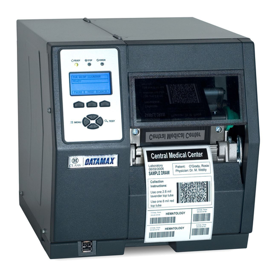
Overview 1.1 About the Printer Congratulations on your purchase of an H-Class printer (hereafter referred to as ‘the printer’). This manual provides information regarding printer setup, operation, and care. To print label formats, refer to the instructions provided with your labeling software; or if you wish to write custom programs, a copy of the Class Series Programmer’s Manual can be... -
Page 12: Standard Features
1.1.1 Standard Features Depending upon the model and type, the printer offers the following standard features: Feature Control Panel Security Default Configuration Restorable Diagnostic Display and Modes Die Cast Media Hub Direct Thermal Printing Downloadable Firmware Upgrades DRAM Memory (MB) -
Page 13: Optional Features
USB Host Ports (2) (internal remote) 1.1.2 Optional Features The following optional features are offered for the printer: 40 mm Media Hub (H-4xxx and H-4xxxX models only) A media hub that accommodates 40-millimeter cores. Cover Dampener (H-6xxx, H-6xxxX, and H-8308X models only) A hydraulic mechanism that stalls sudden cover closures. - Page 14 External Media Rewinders Precision-crafted, bi-directional rewinding mechanisms with device-dependant features: DMXREW1 - accommodates 1 to 4-inch (25 to 101 mm) diameter cores, accepts a • maximum label width of 4.5 inches (114 mm), and rewinds to an 8-inch (203 mm) maximum outer diameter at 10 inches per second.
-
Page 15: Option Installation
A hub assembly that allows printing with ribbon for exceptional image clarity and durability, as compared to most direct thermal media types. Option Installation The table below lists the experience needed to install the options described above. For more information, contact your dealer or Datamax. Option 40 mm Media Hub Cover Dampener... - Page 16 Option Installation (continued) Option Peel and Present Mechanism Present Sensor RFID (Ready and Full Upgrade) SDIO Interface and USB Host Ports Thermal Transfer Recommended Installer Operator Operator DMX Certified Technician DMX Certified Technician Operator H-Class...
-
Page 17: Getting Started
Getting Started 2.1 Unpacking The printer has been carefully packaged to prevent transit damage. (Inspect the container for damage and, if evident, notify the shipping company before acceptance.) After removing the packaging, check the contents of the shipment. The following items are included: Printer •... -
Page 18: Additional Requirements
With printer placed upon a firm and level surface, connect the Power Cord as follows: A. Ensure that the Power Switch is turned OFF. B. Connect the Power Cord to the AC receptacle on the printer, and then to a properly rated and grounded AC outlet. -
Page 19: Connecting The Interface Cable(S)
2.2.2 Connecting the Interface Cable(s) The printer can be interfaced to your host system via the Ethernet, Parallel, Serial, and USB ports. Following power-up (or after a period of inactivity) communications will automatically be established through the first port that receives valid host data. -
Page 20: Usb Connection
"Off the shelf" serial cables can be used with Xon/Xoff handshaking. USB Connection The USB interface connection may differ slightly depending upon the operating system and hardware configuration of the host computer. Basic connections are shown below. H-Class... -
Page 21: Connecting To The Sdio Slot And Usb Host Ports
SDIO Slot Connections: • When installing an SDIO Card, turn OFF the printer then slide the card into the SDIO Slot. After turning ON the printer, Module F will be recognized. When removing an SDIO Card, turn OFF the printer then press the SDIO Card inward to release. - Page 22 USB Host Port Connections: • The USB Host Ports support "plug and play" USB Memory Drives. After installing the drive in the printer, Module H will be recognized. Only one USB Memory Drive at a time will be recognized. •...
-
Page 23: Setting Up The Printer
Setting up the Printer 3.1 Media Loading Load media according to its type and source, after performing these prerequisites: A. Raise the cover. B. Rotate the Printhead Latch counterclockwise then raise the Printhead Assembly. H-Class... - Page 24 C. Slide the Media Guide outward. D. Rotate the Media Guide upward. E. Proceed according to the source of the media being installed: If using internally supplied (roll media) sources, see Section 3.1.1; or, • If using externally supplied sources (e.g., boxed fanfold stock), see Section 3.1.2. •...
-
Page 25: Internal Media Sources
Internal Media Sources A. Slide Roll Media completely onto the Media Hub. B. Route the media under the Media Guide Extrusion then out the front of the printer, as shown. C. Rotate the Media Guide into the DOWN position and then slide the guide inward until it rests lightly against the edge of the media. - Page 26 D. If loading media for the first time, or if switching media types, widths, or configurations, position the Media Sensor as detailed in Section 3.2; otherwise, go to Step E. If loading thermal transfer media, also load ribbon; see Section 3.3. E.
-
Page 27: External Media Sources
B. Route the media into the printer through the Rear Media Loading Slot or Bottom Media Loading Slot, and if equipped over the Rewind Hub. C. Route the media under the Media Guide Extrusion then out of the printer, as shown in the previous section. - Page 28 E. If loading media for the first time, or when switching media types, widths, or configurations, position the Media Sensor as detailed in Section 3.2; otherwise, go to Step F. If loading thermal transfer media, also load ribbon; see Section 3.3. F.
-
Page 29: Rewinding Media
3.1.3 Rewinding Media When equipped with the Internal Rewind option, outputs can be rewound or, with the addition of a Peel and Present option, dispensed automatically for application. If equipped, follow the instructions below to begin using the Internal Rewinder: A. - Page 30 C. Place the Arcplate on the front of the printer (as shown below) and tighten the Phillips Head Screw to secure it; or, to use the Peel and Present option attach that device. D. Proceed according to your application: To rewind labels onto an empty media core (tall models only), go to Step E.
- Page 31 F. Align the Tabs on the Rewind Core Adapter to the Slots in the hub, and then slide the Rewind Core Adapter onto the middle of the hub. G. Grasp the end of the hub and, while pulling outward, squeeze the hub together until it collapses then slide Rewind Core Adapter toward the Centerplate until it locks in place.
- Page 32 H. Slide an Empty Media Core (3” diameter) onto the Rewind Core Adapter. I. Slide the Rewind Retainer into the Empty Media Core then close the Locking Lever. J. H-8308X users (all others go to Step K), close the Rewind Support then rotate the latch 1/4 turn clockwise to lock the Rewind Support.
- Page 33 L. Route the media back into the printer and around the media core (as shown below) then tape the leading edge to the media core. M. Enter the menu, go to PRINTER OPTIONS / REWINDER, and select Enable. Exit the menu and save your changes.
- Page 34 Unloading the Internal Rewinder To unload the Internal Rewinder, open the Locking Lever, remove the Rewind Retainer, and slip the roll of labels (and core) off the Rewind Core Adapter. Removing the Adapter Core To switch from label rewinding to label peeling, remove the Rewind Adapter Core as follows: A.
-
Page 35: Media Sensor Adjustment
3.2 Media Sensor Adjustment Position the Media Sensor for proper label detection: A. Raise the Printhead Assembly. Note the Red Dot (see illustration below) that identifies the location of the Media Sensor. B. Grasp the Slide Tab to position the Red Dot according to the Media Type, as detailed below. -
Page 36: Ribbon Loading
C. Lower the Printhead Assembly then rotate the Printhead Latch completely clockwise. D. If necessary, return to Media Loading to complete the setup process; otherwise, close the cover. With READY displayed, press and hold the FEED Key until at least one gap (or mark) advances;... - Page 37 Side Out), slide a Ribbon Roll completely onto the Ribbon Supply Hub, as shown below. The coated (inked) side of the ribbon must face the media. Coated Side In (CSI) Ribbon Coated Side Out (CSO) Ribbon C. Route the ribbon under the Ribbon Idler then out the front of the printer. H-Class...
- Page 38 E. Route the ribbon up and around the Ribbon Take-Up Hub. Wrap the ribbon several times clockwise (as indicated by the directional arrows) around the hub to secure it. F. Lower the Printhead Assembly then rotate the Printhead Latch completely clockwise. G.
-
Page 39: Quick Calibration
Quick Calibration fine-tunes the printer for your media and should be performed during initial setup or after switching media. With media installed and the sensor position adjusted, perform calibration as follows: With the printer idle, press and hold the FEED Key until one complete label advances • and then release the key. - Page 40 H-Class...
-
Page 41: Using The Control Panel
Using the Control Panel 4.1 Layout The Control Panel is an event-driven user interface composed of a graphics display and keyboard. Note that depending upon the display size the layout and composition differs: Small Display Control Panel Large Display Control Panel H-Class... -
Page 42: The Display, Icons And Indicators, And Keys And Buttons
RFID is detected. A wired network is detected. WLAN is associated with a WLAN Access Point. WLAN is enabled, but the printer is NOT associated with a WLAN Access Point. WLAN is in ADHOC mode. The printer is receiving data. -
Page 43: The Menu System
COMMUNICATIONS • DIAGNOSTICS • MCL OPTIONS • Entering the menu system takes the printer off-line and halts the processing of • new data. Prompts may appear before menu access is granted and changes enacted; see • Section 5.1.1. The MENU MODE setting controls menu level access; see, Section 4.2.4. - Page 44 Press the Menu Button to enter Menu Mode. The following designations denote setting icons used in the menu listing below: Symbol Definition Default setting ♦ Setting can only be changed via the Menu System. H-Class...
-
Page 45: Media Settings
Determines the length of the label when the SENSOR TYPE is set to CONTINUOUS, where: Is the desired length of the format. Sets the distance that the printer will feed GAP or REFLECTIVE media before declaring a TOF fault, where: Is the length of travel to detect a TOF gap or mark. - Page 46 Sets the threshold that will trigger a Low Ribbon Warning prompt, where: Is the outer diameter size of the ribbon roll. Sets the printer to pause when the Ribbon Low Diameter setting is met, where: Forces the user to press the PAUSE Key to proceed with the print job.
- Page 47 Media Settings (continued) Menu Item PRINTHEAD CLEANING CLEAN HEAD SCHEDULE 000 0 – 200 in. (* 1000) CLEAN HEAD COUNTER RESET COUNTER CLEAN HEAD NOW H-Class Details Controls printhead cleaning alerts and functions, where: Specifies the inch (or centimeter) count (multiplied by one thousand) at which to clean the printhead.
-
Page 48: Print Control
4.2.2 Print Control The Print Control menu contains print quality, throughput, formatting, and custom setup functions: Menu Item HEAT 10 (0 – 30) PRINT SPEED XX.Xin/sec FEED SPEED XX.Xin/sec REVERSE SPEED X.Xin/sec SLEW SPEED XX.Xin/sec ROW OFFSET 00.00 (0 – 99.99 in.) COLUMN OFFSET 00.00 (0 –... - Page 49 These selections independently change the listed parameters, allowing slight mechanical compensations sometimes evident when multiple printers share label formats or for special printer-specific formatting adjustments, where: Controls the printhead strobe time (see HEAT, above) to fine-tune the solid areas of an image.
-
Page 50: Printer Options
4.2.3 Printer Options The Printer Options menu contains module, file handling, and option functions: Menu Item MODULES DIRECTORY PRINT FILE PROCESS FILE FORMAT MODULE DELETE FILE COPY FILE UNPROTECT MODULE Details Controls memory handling functions, where: Allows viewing and printing of available space and file types (including plug-ins) present on a module. - Page 51 H-Class Details Controls the Present Sensor or the Peel and Present option, where: Sets the detection method and response of the printer, where: Disables the option. Detects, enables, and sets the label stop location for the sensor option; if not detected, the option will be ignored.
- Page 52 UPC(A/E)+5 BARCODE COUNT (0 - 99) Details Controls the Linear Scanner option, where: Sets the detection method and response of the printer, where: Disables the option. Detects and enables the scanner; if not detected, the option will be ignored. Enables the scanner; if not detected, a fault will be generated.
- Page 53 Printer Options (continued) Menu Item MIN READABLE HEIGHT DISABLED 1/16 – ½ in. (1.5 – 12.5 mm) REDUNDANCY LEVEL READ BARCODE 2X (1X – 6X) AUTO SET DEFAULTS H-Class Details Ensures bar code integrity by setting a minimum distance for identical decodes, where: Uses REDUNDANCY LEVEL to ensure bar code integrity.
- Page 54 Sets the RFID encoding position, where: Is the inlay location (as referenced from the leading edge of the tag moving forward through the printer), where 0.00 uses the print position to encode tag and values greater use the present position (subject to change).
- Page 55 Printer Options (continued) Menu Item AFI LOCK ENABLED DISABLED DSFID VALUE (00 – FF) DSFID LOCK ENABLED DISABLED EAS VALUE (00 – FF) AUDIO INDICATOR ENABLED DISABLED ERASE ON FAULT ENABLED DISABLED H-Class Details Locks the Application Family Identifier value, where: Is write-protected.
- Page 56 Printer Options (continued) Menu Item UHF SETTINGS TAG TYPE EPC 0 EPC 0+ MATRICS EPC 0+ IMPINJ EPC 1 UCODE EPC 1.19 EM 4022/4222 GEN 2 TAG DATA SIZE 96-BIT 64-BIT POWER ADJUST (dBm) 000 (-04 KILL CODE 00 00 00 00...
- Page 57 Does not lock the tag. Sets the number of retry attempts, where: Is the retry count before a fault is declared. Allows the printer to establish the tag to transducer distance and nominal power setting, where: Initiates the process; CALIBRATING RFID will be...
- Page 58 Printer Options (continued) Menu Item GPIO PORT GPIO DEVICE DISABLED APPLICATOR APPLICATOR 2 BARCODE VERIFIER START OF PRINT LOW PULSE HIGH PULSE ACTIVE LOW ACTIVE HIGH EDGE Details Controls the optional Applicator Interface Card’s GPIO function, where: Sets the option to work with a specific device type, where: Disables the option.
- Page 59 Printer Options (continued) Menu Item END OF PRINT LOW PULSE HIGH PULSE ACTIVE LOW ACTIVE HIGH RIBBON LOW ACTIVE LOW ACTIVE HIGH SLEW ENABLE STANDARD LOW PULSE HIGH PULSE ACTIVE LOW ACTIVE HIGH H-Class Details Sets the type of output signal generated to indicate End of Print (EOP), where: Outputs a low pulse upon completion.
- Page 60 REWINDER ADJUSTMENT 00 (-30 – 15 %) Details Controls the Powered Internal Rewinder option, where: Sets the detection method and response of the printer, where: Disables the option. Enables the rewinder only when a Peel and Present option is installed; however, no error will be generated when the Peel and Present option is not attached.
-
Page 61: System Settings
Sets the menu system access level, where: Accesses limited basic menu items. Accesses all menu items. Controls the creation, storage, and recall of printer configuration files (see Appendix E), where: Lists the files available and then, after selection, reconfigures the printer according to that file. - Page 62 System Settings (continued) Menu Item DOUBLE BYTE SYMBOLS SHIFT JIS UNICODE BIG 5 TIME AND DATE SET HOUR 06:30 PM 20 AUG 2007 MEDIA COUNTERS ABSOLUTE COUNTER PRINTHEAD COUNTER RESETTABLE COUNTER RESET COUNTER PRINT CONFIGURATION Details Selects the code page (see the Class Series Programmer’s Manual) used for the ILPC option (unless otherwise specified), where: Selects Japanese Industry Standard.
- Page 63 Details Displays the hardware and software levels of the printer, where: This data is also provided on the Configuration Label. Identifies the unique key number of the printer, in the form: vvvv-cwxx-yyyyyy-zzz Where: – Represents the printer model number. vvvv –...
- Page 64 System Settings (continued) Menu Item SET FACTORY DEFAULTS FORMAT ATTRIBUTES TRANSPARENT OPAQUE LABEL ROTATION ENABLED DISABLED IMAGING MODE MULTIPLE LABEL SINGLE LABEL PAUSE MODE ENABLED DISABLED Details Returns the factory-programmed values or the Factory Setting File values, where: Restores the default settings, or if selected the Factory Setting File.
- Page 65 Modifies the security password, where: Allows entry four-digit confirmation). To be activated, the default password (0000) must be changed. Exits the menu item without changing the current settings. Sets the measurement standard of the printer, where: Uses inches. Uses millimeters and centimeters. password (after...
- Page 66 System Settings (continued) Menu Item INPUT MODE LINE PL-Z COLUMN EMULATION XXX (XXX – XXX DOTS) ROW EMULATION XXX (XXX – XXX DOTS) SOP EMULATION DISABLED 110 (PRODPLUS) 220 (ALLEGRO) 250 (PRODIGY) Details Defines the type of processing that occurs when data is received, where: See the Class Series Programmer’s Manual for detailed information.
- Page 67 Prints using a downloaded font. Determines the command recall level when retrieving stored label formats, where: Recalls the printer state (i.e., heat, speeds, etc.) and the formatting commands for a stored label. Recalls the formatting commands for a stored label.
- Page 68 Selects the user action and reprint status upon declaration of a fault, where: Without the Linear Scanner option, the printer will perform in the STANDARD setting and VOID will be printed on the faulted label.
- Page 69 Counts greater than one are only valid when equipped with the Linear Scanner or RFID option. Determines the printer's action after a fault is cleared, where: Positions the label after the fault is cleared. Does not position the label; the current position is assumed correct.
-
Page 70: Communications
4.2.5 Communications The Communications menu contains interface port and host control functions: Menu Item SERIAL PORT A ♦ BAUD RATE 9600 BPS 115000 BPS 57600 BPS 38400 BPS 28800 BPS 19200 BPS 4800 BPS 2400 BPS 1200 BPS PROTOCOL BOTH SOFTWARE HARDWARE NONE... - Page 71 The maximum baud is 38.4K BPS. Controls the communications settings for Parallel Port A, where: Allows printer data to be returned to the host, where: Returns no data (one-way communication). Returns data (compliant back-channel operation); see Section 2.2.2 for cable requirements.
- Page 72 Communications (continued) Menu Item WLAN MODE ENABLED DISABLED BSS ADDRESS 192.168.010.001 SIGNAL READINGS IP ADDRESS 192.168.010.026 SUBNET MASK 255.255.255.000 GATEWAY 192.168.010.026 SNMPTRAP DESTINATION 000.000.000.000 Details Controls the communications settings for the optional DMXrfNETII Card, where: Selects between wired and WiFi operation, where: Enables the WiFi interface.
- Page 73 Sends messages to SNMP-compliant devices. Sends no messages. Allows a network status report to be viewed or printed, with content similar to the example below: NETWORK REPORT PRINTER STATUS MACO: NOT SET IP ADDRESS: 192.168.10.26 SUBNET MASK: 255.255.255.0 GATEWAY: 192.168.10.26...
- Page 74 Are the codes according to your definitions. Standard codes serve as default placeholders. Allows the return of printer codes, where: Sends the host a Hex 1E (RS) after each label and a Hex 1F (US) after each batch successfully prints.
- Page 75 Communications (continued) Menu Item HEAT COMMAND ENABLED DISABLED SPEED COMMANDS ENABLED DISABLED TOF SENSING COMMANDS ENABLED DISABLED SYMBOL SET COMMAND ENABLED DISABLED CNTRL-CODES (DATA) ENABLED DISABLED STX-V SW SETTINGS ENABLED DISABLED H-Class Details Determines how host Heat commands are handled, where: Processes software commands normally.
- Page 76 D - Is the number of good reads for bar codes or tags, given in two characters. E - Is the printer’s internal Job and Sub Job Identifier, given in four characters each. F - Is the data that was read, delimited with semicolons (;) on multiple reads.
-
Page 77: Diagnostics
TEST REWINDER PERFORM TEST 001 TIMES H-Class Details Determines how the printer handles host data, where: Processes data normally. Prints received ASCII data without interpretation or processing; see Section 6.3. Saves received data to Module G (or Module H, if present) in the form dmx_xxx_yyy.dpl... - Page 78 Diagnostics (continued) Menu Item TEST GPIO MONITOR GPIO INPUT FEED PAUSE REPRT TEST GPIO OUTPUT EP RL SR MO RO DR OF PRINT SIGNAL INFO Details Tests the Applicator Interface Card’s GPIO function, where: Displays input signal logic values for Start of Print (SOP), Feed, Pause, Reprint, and six unassigned input lines.
- Page 79 Diagnostics (continued) Menu Item TEST SCANNER ALIGNMENT TEST SCAN TEST TEST RFID TAG DATA DEVICE VERSION TAG ID – HF ONLY PRINT TEST RATE (min) 000 (0 – 120) SENSOR READINGS TRAN RIBM RANK RIBBON SENSOR LIMITS RIBBON ADC LOW RIBBON ADC HIGH H-Class Details...
-
Page 80: Mcl Options
CLEAN COUNTER RESET 5 NUMBER OF INCHES LAST- 0 Details Allows the printer to use the optional MCL tool suite to accept peripheral device input data, where: Allows MCL start-up, where: Sets MCL operation after power is cycled OFF and ON,... -
Page 81: The Test Menu
The (Quick) Test Menu contains internally generated setup and informational format selections that are printed at pre-selected heat and speed settings. When printing, use full width media to capture the entire format; otherwise, adjust the printer and set the Label Width. -
Page 82: Ribbon Test Label
4.3.2 Ribbon Test Label The Ribbon Test Label serves as a transfer function indicator for printers equipped with the thermal transfer option. Consisting of a fence-oriented bar code, this format can be used to ensure component functions and ribbon path alignment. -
Page 83: Print Configuration
The User-Defined Label allows a template to be populated by variable data (via the printer's control panel or a USB qwerty keyboard). The template is a stored label format, where fields delimited by the "&" become variable. The printer will prompt the user to enter these variable field data. - Page 84 H-Class...
-
Page 85: Operating, Adjusting And Maintaining The Printer
Operating, Adjusting and Maintaining the Printer 5.1 Display Messages During operation the printer (when not in Menu or Test Mode) displays several types of information: Prompts and Condition Messages (see Section 5.1.1); • Firmware Downloading Messages (see Section 5.7); •... - Page 86 This is the menu gateway. An incorrect entry has been made. The selected option or feature cannot be found. The printer is in Menu or Test Mode. The printer is in a paused condition. Automatic printhead cleaning is in progress.
- Page 87 The Media Sensor is not calibrated. Start of Print signal has been received, but the printer awaits label data. The printer awaits a Start of Print signal from the host. The print job is underway. Action / State Ribbon must be removed and a key pressed to proceed with cleaning.
-
Page 88: Calibration
Before proceeding, ensure that the ADVANCED MENU is enabled (see Section 4.2.4) and that the SENSOR TYPE is selected (see Section 4.2.1). Step Action Turn ON the printer. Press ENTER to access MEDIA SETTINGS. Then using the UP Button, scroll to SENSOR CALIBRATION. - Page 89 Media Sensor after this step. media, ensure that the area placed over the sensor is free of text, graphics, or borders.
-
Page 90: Advanced Entry Calibration
Calibrate the Media Sensor using the steps below: Displayed Message Calibration was successful. CALIBRATION COMPLETE Backing’ is displayed, calibration was successful (for possible messages see Section 5.1). CALIBRATION COMPLETE The printer is now ready Followed by... for use. READY Comment If ‘Warning Low H-Class... - Page 91 Advanced Entry Calibration Step Action Turn ON the printer. Press ENTER to access MEDIA SETTINGS. Then using the UP Button, scroll to SENSOR CALIBRATION. Press ENTER to access SENSOR CALIBRATION. Using the DOWN Button, highlight ADVANCED ENTRY then press ENTER.
- Page 92 Advanced Entry Calibration (continued) Step Action Use the buttons to set the Gain Number to 00 and then press ENTER. Record the sensor reading as a Label Value for Gain Number 00 in a table (32 rows by four columns, with headings similar to those shown below.) Gain Number...
- Page 93 Advanced Entry Calibration (continued) Step Action Raise the printhead assembly then proceed according to the media type: Die-cut – Remove a label • or two from the liner then position that area over the Media Sensor. Adjust the Media Sensor under the liner area.
- Page 94 Advanced Entry Calibration (continued) Step Action Use the buttons to increment the Gain Number by one and then press ENTER. Record the TOF Value. Repeat this process for each Gain Number. Gain Number … Step Action In your sample calibration table, where both the Label Value and TOF Value are at least 20, subtract...
- Page 95 Advanced Entry Calibration (continued) Step Action Use the buttons to set the Gain Number determined in the previous step. Press ENTER to enable the setting. Complete a table (see example below) using new measurements, as follows: (A) Raise the Printhead Assembly.
- Page 96 Advanced Entry Calibration (continued) Step Action Press the ESC Key. Use the buttons to scroll to PAPER SENSOR LEVEL (or if using reflective media, REFL PAPER LEVEL) and then press ENTER. Use the buttons to set the Paper value determined in Step M and then press ENTER.
- Page 97 Advanced Entry Calibration (continued) Step Action Press and hold the FEED Key until at least one label has been output. H-Class Displayed Message The printer is ready for use. CALIBRATION COMPLETE Followed by... READY Comment If the calibration attempt fails, try...
-
Page 98: Reset Methods
Level Two Reset Level Two returns the factory default settings and clears all parameters. To perform a Level Two Reset: While turning ON the printer, press and hold the three Soft Keys (see Section 4.1) • until the SYSTEM RESET message flashes. - Page 99 Adjust the Printhead Leveling Cam as follows: A. With media loaded, download your label format (or use a Test Menu format) then begin printing a small batch of labels. B. While observing the printed output, rotate the Leveling Cam counter-clockwise until the image fades across the label, as shown in Example 1 (below).
-
Page 100: Printhead Pressure Adjustment
5.4.2 Printhead Pressure Adjustment Printhead Pressure Adjustment should only be performed after attempting to improve print quality through the use of other print quality controls (see Section 7.4). A. With media loaded, download your label format (or use a Test Menu format) then begin printing a small batch of labels. -
Page 101: Printhead Removal And Replacement
• Technical Support before proceeding. A. Turn OFF the power switch then touch a bare metal printer surface (e.g., the frame) to discharge any static electricity present on your body. B. Unplug the printer and open the access cover. If ribbon is installed, remove it. -
Page 102: Maintenance
G. Using a Cotton Swab moistened (not soaked) with isopropyl alcohol, gently clean the printhead then allow it to dry. H. If removed, reinstall ribbon. Lower and lock the Printhead Assembly. Plug in the printer and turn ON the power switch. Print a Validation Label (see Section 4.3.4) then compare the contrast levels between the current label and a previously printed label;... - Page 103 Schedule The following table details the recommended cleaning schedules for various printer parts. Recommended Cleaning Schedule* Component / Area As needed, based on a weekly visual Exterior Surfaces inspection. Fan Filter As needed, based on a weekly visual inspection. (tall models only)
-
Page 104: Cleaning The Exterior Surfaces
5.6.2 Cleaning the Fan Filter On equipped models, a Fan Filter keeps dust and debris from entering the printer. To assure continued airflow through the printer, clean the Fan Filter as follows: A. Turn OFF the Power Switch and unplug the power cord from the AC Receptacle. -
Page 105: Cleaning The Interior Compartment
5.6.3 Cleaning the Interior Compartment Inside the printer, paper dust from the media can accumulate to produce small voids in the print. To assure continued void free printing, clean the Interior Compartment as follows: A. Turn OFF the Power Switch and unplug the power cord from the AC Receptacle. -
Page 106: Cleaning The Platen And Assist Rollers
5.6.5 Cleaning the Platen and Assist Rollers Rollers contaminated with grit, label adhesive, or ink can lead to a decline in print quality and, in extreme cases, cause labels to adhere and wrap the roller. Clean the Platen and Assist Rollers as follows: A. -
Page 107: Cleaning The Printhead
To help you remember this important maintenance procedure, the printer can be programmed to prompt you for cleaning; see Section 4.2.1. Depending upon to the supplies and printing parameters used, different methods are recommended for cleaning. - Page 108 A. Perform the Preliminary Cleaning Steps, as described above. B. Turn OFF the power switch and unplug the printer. Using a Cotton Swab moistened (not soaked) with isopropyl alcohol, gently clean the printhead surface of all build-up.
-
Page 109: Cleaning The Ribbon Path Components
Allow the printhead to dry. F. Reinstall media (and ribbon, if necessary). Plug in and turn ON the printer. Run a few sample labels and examine them. If streaking is still present the printhead may need to be replaced;... -
Page 110: Updating The Firmware
B. Turn OFF the printer. Connect your computer to the printer via the parallel or USB port, and then turn ON the printer. C. Using the Windows print driver, open the Printer Properties box and select the 'Tools' tab. - Page 111 Following a successful download, the printer will reset. Unless substantial data structure changes have occurred as a result of the firmware upgrade, the previous printer setup will remain intact; otherwise, you may need to calibrate the printer and enter any custom settings.
-
Page 112: Updating The Boot Loader
5.8 Updating the Boot Loader Updates for the Boot Loader program can be found at Before performing an update, identify the printer’s current Boot Loader version by printing a Configuration Label (see Section 4.2.4) and comparing the installed version to those available from the FTP site. -
Page 113: Downloading Fonts
B. Call to get the unlock code and enter it into the printer. Turn OFF the printer. C. Turn OFF the printer. Connect your computer to the printer via the parallel or USB port, and then turn ON the printer. - Page 114 Try the download again; however, if the problem continues call for service. The file was successfully installed; the printer will perform an SUCCESSFUL automatic reset. Insufficient memory space for the file exists in the destination SYSTEM FAULT module.
-
Page 115: Troubleshooting
Depending on your labeling program and the printer's menu settings, some commands and selections can be ignored. See HOST SETTINGS (Section 4.2.5) for more information and consult your software vendor for program information. If you have questions or if problems persist, contact a qualified technician or Datamax Technical Support. 6.1.1... - Page 116 • You may be using an incorrect type – Intellifont ™ Intellifont will not Little/Big Endian specific and the printer uses Big Endian; refer print: to your font supplier for information. Check the following possibilities: Light print on the side •...
- Page 117 Verify that the AC power cord is connected to the outlet and to the printer, and that the power switch is ON; Verify that the AC outlet is functioning, or move the printer to another location on a different circuit;...
- Page 118 General Resolutions (continued) If experiencing this problem… Ensure that the printer is at READY then observe the display when sending your label format to the printer and proceed accordingly: • No print when using a software program (Test labels print normally): •...
-
Page 119: Warning And Fault Messages
Warning Messages Displayed for about three seconds, Warning Messages assume a low priority and are meant to alert you to a pending change in printer configuration, or to a current operating condition that could lead to a fault. Displayed Message... - Page 120 Possible low or fluctuating line voltage levels have been The printer has detected sensed. If the condition a low operating voltage. persists, try moving the printer to another outlet, or call for service. The internal rewinder is Unload the internal rewinder nearing capacity.
-
Page 121: Fault Messages
Fault Messages These high priority messages alert you to a printer fault condition. Use the table below to locate the displayed message, associated description of the problem and possible solution. (Alternate messages may occur when downloading font, firmware, or boot loader files.) To return operation after a fault occurs, the fault must be corrected and the FEED Key pressed. - Page 122 A memory failure has ON. If the fault does not clear, been detected. call for service. Possible Solution(s) If the printer is out of stock, load media; or, If stock is loaded, ensure that the Media Sensor is calibrated (see Section 3.4), properly positioned...
- Page 123 Possible Solution(s) If full, unload the internal rewinder then press the FEED Key to clear the fault; If not full, cycle printer power OFF and ON. If the fault does not clear, call for service. To continue printing, enter...
- Page 124 FEED Key until at least three labels have been output. If the fault does not clear, call for service. Turn OFF the printer. Ensure The printer has that the printer has been shutdown due to the installed within an acceptable printhead temperature.
- Page 125 TOP OF FORM FAULT H-Class Fault Messages (continued) Description Check the following possibilities: • • The printer could not find a TOF mark within the maximum length setting, or TOF was encountered • in an unexpected place. When the SENSOR TYPE is REFLECTIVE, •...
-
Page 126: Hex Dump Mode
To decode data strings the Class Series Programmer’s Manual is an essential reference (see the Accessories CD-ROM). Also, some software programs use bit mapping, which can make diagnosis difficult – contact Datamax Technical Support with any questions. To return the normal operating mode, enter the DIAGNOSTICS and disable HEX DUMP MODE. -
Page 127: Specifications
Specifications 7.1 General This section identifies shared parameters and features of the printer models. Embedded Bar Codes & Fonts See Appendix B for a listing and samples (and the Class Series Programmer’s Manual for details). Communications Interface Types: Serial Data Rates (RS-232):... -
Page 128: Model-Specific Specifications
Storage Temperature: Humidity Range: Dust: Electromagnetic Radiation: 7.2 Model-Specific Specifications This section identifies unique parameters and features of the printer models, where the “X” suffix also denotes the tall version of the model. H-4212, H-4310, H-4408, & H-4606 Models Mechanical Height:... - Page 129 Printing (continued) Resolution: Dot Size (nominal): Tear Bar: Media Types: Internal Capacity: Ribbon Width Range: Ribbon Length: Dimensions: Side View H-Class 203 DPI (8 dots/mm); H-4212 300 DPI (12 dots/mm); H-4310 406 DPI (16 dots/mm); H-4408 600 DPI (23.6 dots/mm); H-4606 .0043"...
- Page 130 The reflective (black) mark must be carbon based, placed on the backside of the stock, and the reflectance shall be less than 10% at wavelengths of 950 and 640 nm. The maximum allowable length of the combined label and gap (or mark) measurement cannot exceed 99.99 inches. H-4212X, H-4310X, & H-4606X Models Mechanical Height: Width:...
- Page 131 Side View H-Class Direct Thermal or (optional) Thermal Transfer 2 - 12 IPS (51 - 305 mmps); H-4212X 2 - 10 IPS (51 - 254 mmps); H-4310X 2 - 6 IPS (51 - 152 mmps); H-4606X 203 DPI (8 dots/mm); H-4212X 300 DPI (12 dots/mm);...
- Page 132 Media (continued) H-4212X, H-4310X, & H-4606X Media Dimensional Requirements Designator Description Label width Liner width Gap (or notch) between labels Label length Media thickness Notch opening width Media edge to sensor aperture Reflective mark width Distance between reflective marks Reflective mark length Label repeat distance Units of measure are referenced by the direction of label feed.
- Page 133 Printing Method: Speed: Resolution: Dot Size (nominal): Tear Bar: Media Types: Internal Capacity: Ribbon Width Range: Ribbon Length: Dimensions: Side View H-Class Direct Thermal or (optional) Thermal Transfer 2 - 10 IPS (51 - 254 mmps); H-6210 2 - 8 IPS (51 - 203 mmps); H-6308 203 DPI (8 dots/mm);...
- Page 134 Media (continued) H-6210 & H-6308 Media Dimensional Requirements Designator Description Label width Liner width Gap (or notch) between labels Label length Media thickness Notch opening width Media edge to sensor aperture Reflective mark width Distance between reflective marks Reflective mark length Label repeat distance Units of measure are referenced by the direction of label feed.
- Page 135 Printing Method: Speed: Resolution: Dot Size (nominal): Tear Bar: Media Types: Internal Capacity: Ribbon Width Range: Ribbon Length: Dimensions: Side View H-Class Direct Thermal or (optional) Thermal Transfer 2 - 12 IPS (51 - 305 mmps); H-6212X 2 - 10 IPS (51 - 254 mmps); H-6310X 203 DPI (8 dots/mm);...
- Page 136 Media (continued) H-6212X & H-6310X Media Dimensional Requirements Designator Description Label width Liner width Gap (or notch) between labels Label length Media thickness Notch opening width Media edge to sensor aperture Reflective mark width Distance between reflective marks Reflective mark length Label repeat distance Units of measure are referenced by the direction of label feed.
- Page 137 Printing Method: Speed: Resolution: Dot Size (nominal): Tear Bar: Media Types: Internal Capacity: Ribbon Width Range: Ribbon Length: Dimensions: Side View H-Class Direct Thermal or (optional) Thermal Transfer 2 - 8 IPS (51 – 203 mmps) 300 DPI (12 dots/mm) .0027"...
-
Page 138: Approved Media And Ribbon
For complete information and advice regarding a specific application, consult a qualified media specialist or a Datamax Media Representative. Also available is an informative white paper, "A Brief Introduction to Media,"... -
Page 139: Media And Ribbon Selection
These supplies are specially formulated for use in our printers; use of non-Datamax supplies may affect the print quality, performance, and life of the printer or its components. For a current list of approved media, please contact a Media Representative at (407) 523-5650. -
Page 140: Print Quality Controls
7.4 Print Quality Controls The printer provides flexible print controls. Of these, the amount of heat applied and the rate of media movement will have the most effect on the printed output. Four settings are available via PRINT CONTROL (see Section 4.2.2): HEAT -- adjust this setting to lighten or darken the print contrast;... -
Page 141: Appendix A
USB Thumbdrive (Optional, for port-equipped models only) FLASH (Main Logic Card) FLASH (Main Logic Card) File Handling Definitions The following file types are supported and, as noted, converted by the printer. Process File Handling (see Section 4.2.3) File Type BMP, PCX, and IMG Industry standard black and white graphics formats. - Page 142 A true type or scalable font file created after download using the <STX>i command (see the Programmer's Manual) or "Process File" (see the Printer Options / Modules menu). This can be used for label or display fonts. A converted PLG file. (Encrypted types cannot be copied.)
- Page 143 File Handling Messages (continued) Displayed Message The request has been MODULE PROTECTED denied because the module is protected. No associated files can NO FILES AVAILABLE be found to perform the requested action. The file requested is NOT SUPPORTED not a supported type. The file requested will PROTECTED, PROTECTED be copied to a...
- Page 144 H-Class...
-
Page 145: Resolutions, Widths, Speeds, Emulations, And Custom Adjustment Settings
Appendix B Resolutions, Widths, Speeds, Emulations, & Custom Adjustments Print Resolutions and Widths Printhead Model Resolution H-4212 & 203 dots/inch H-4212X (8 dots/mm) H-4310 & 300 dots/inch H-4310X (12 dots/mm) 406 dots/inch H-4408 (16 dots/mm) H-4606 & 600 dots/inch H-4606X (23.6 dots/mm) - Page 146 Speed Ranges Model Function Print Feed H-4212 & H-4212X Reverse Slew Print Feed H-4310 & H-4310X Reverse Slew Print Feed H-4408 Reverse Slew Print Feed H-4606 & H-4606X Reverse Slew Print Feed H-6210 Reverse Slew Print Feed H-6212X Reverse Slew...
- Page 147 Custom Adjustment Ranges Row, Column, and Present Adjust Ranges (in dots) Model H-4212, H-4212X & H-6212X H-4310, H-4310X, H-6308, H-6310X, & H-8308X H-4408 H-4606 & H-4606X Column & Row Emulation Ranges Model H-4212, H-4212X & H-6212X H-4310, H-4310X, H-6308, H-6310X, & H-8308X H-4408 H-4606 &...
- Page 148 H-Class...
-
Page 149: Appendix C
2. Remove the communication cables from the Main Board. 3. Loosen and remove the two Screws securing the Main Board to the printer. 4. Slide the Main Board out of the printer then move the jumpers according the needs of the application: For RS-422/485 operation, place the jumper across pins E4 and E5;... - Page 150 Communication Jumper locations: +5 Volts Jumper location: 5. Slide the Main Board into the printer and secure it with the two previously removed Screws. 6. Connect communication cables to the Main Board and plug in the power cord. For RS-422/485 communications, ensure that your cable meets the requirements for proper data transfer (per the table, right).
-
Page 151: Appendix D
Appendix D Changing the Display Language Different languages and / or Datamax-provided translations can be downloaded to replace the standard English menu by constructing a spreadsheet that defines the printer dictionary. To change the language you will add a new language column (or modify the existing column) in the spreadsheet, click on the ‘Generate DPL file(s)’... - Page 152 B. Click the “Enable Macro” box. The following screen appears: C. Click On Column J and enter your new language, or modify an existing one. Some tips on this process: Message Size – When entering new messages, reference the ‘MAX’ column: this is •...
- Page 153 An error has occurred if the menu system displays the new language selection, but all the displayed messages remain in English. In this case, re-check your process or contact Datamax Technical Support (be prepared to provide the Common.xls and DPL download files created). Other possible error messages are as follows:...
- Page 154 To restore the factory generated EFIGS image, download the file *832296.01A to the • printer. This file is located on the Datamax FTP site. The letter at the end of the file name (e.g., A) specifies the revision. The latest revision will be available on the FTP site.
-
Page 155: Appendix E
Configuration files save and restore printer settings, eliminating the need for special repeated printer setups. Unique filenames can be assigned and settings restored via the host or printer menu. The following example saves a media calibration as a configuration file: If file sharing among multiple printers, DO NOT include unique parameters (such as calibrations and adjustments). - Page 156 H-Class...
-
Page 157: Appendix F
HTML pages, see Appendix G). G. After entering the addresses, press EXIT and save your changes when prompted. H. Turn OFF the printer and connect the Ethernet cable. Turn ON the printer and then install the port and printer driver using the Windows and Port Setup (see Appendix H). - Page 158 Depending upon your server, you may have to wait a minute or two for the Assigned IP Address to appear on the Configuration Label. F. After the Assigned IP Address has been obtained, install the port and printer driver using ®...
-
Page 159: Appendix G
The resident HTML (Web) pages allow configuration of network and printer settings, status queries, and diagnostic tests. To configure the Print Server and other internal printer settings, you can access the printer via HTML pages using any Web browser. Samples and comment text is given in the screenshots that follow. - Page 160 Network Status page: TCP/IP Configuration page: H-Class...
- Page 161 System Settings, Media Settings, and Print Control pages: Many internal settings can be controlled remotely. For more information on the function of these settings see the corresponding function description in the Menu (Section 4.2). H-Class...
- Page 162 H-Class...
- Page 163 Printer Options, Communications, and Diagnostics pages: H-Class...
- Page 164 Network Print Options page: H-Class...
- Page 165 Reset Network Parameters page: Change Password page: H-Class...
- Page 166 H-Class...
-
Page 167: Appendix H
Appendix H Printer Driver and Port Setup Install the Printer Driver and Port software according to the host’s operating system. Windows 95/98 Driver and Port Installation Start the Windows “Add Printer Wizard” and this screen should appear. Click ‘Next>’. Click on ‘Have Disk’. - Page 168 Windows 95/98 Driver and Port Installation (continued) Browse to the “\DRIVERS\Seagull” folder on the CD- ROM, ensure the file “Datamax for 95, 98, ME, 2000, and xp.inf” is selected and click ‘OK’. Select your printer from the list and then click ‘Next’.
- Page 169 Click on the ‘Details’ tab and then click ‘Add Port’. H-Class Once the Printers window opens, right-click on the printer icon and select ‘Properties’ from the drop down menu. In the ‘Add Port’ window, Select ‘Other’ and “Seagull Scientific Port” and...
- Page 170 Windows 95/98 Driver and Port Installation (continued) In the ‘Name or IP Address:’ field, enter the IP address of your printer. The ‘Port Number’ and ‘Port Name’ fields do not need to be changed. When finished click “OK’ Windows NT 4.0 Driver and Port Installation Start the Windows “Add Printer...
- Page 171 Double-click ‘LPR Port’. Click ‘Close’. Click on ‘Have Disk’. H-Class In the top field enter the IP address of your printer. In the bottom field enter PORT1. When finished click “OK’. Click ‘Next’. Insert the Accessories CD- ROM and click ‘Browse’.
- Page 172 Windows NT 4.0 Driver and Port Installation (continued) Browse to the “\DRIVERS\Seagull\ Nt4\” folder on the CD-ROM, ensure the file “Datamax for nt 4.0 only…” is selected and click ‘Open’. Select your printer from the list and then click ‘Next’.
- Page 173 Your computer will now copy the necessary files from the CD-ROM. The driver and port installation is now complete. The printer can be selected through any Window’s application. Windows 2000 Driver and Port Installation Start the Windows “Add Printer Wizard”. The...
- Page 174 Windows 2000 Driver and Port Installation (continued) Select on ‘Create a new port:’ and then select ‘Standard TCP/IP Port’ from the drop down menu. Click ‘Next’. In the ‘Printer Name or IP Address:’ field enter the IP address of your printer. The ‘Port Name’ field does not need to be changed.
- Page 175 Then Click ‘Next’. H-Class Browse to the “\DRIVERS\Seagull” folder on the CD- ROM, ensure the file “Datamax for 95, 98, ME, 2000, and xp.inf” is selected and click ‘OK’. Select your printer from the list and then click ‘Next’.
- Page 176 ‘Yes’ to continue installation. Confirm your settings and then click ‘Finish’. Your computer will now copy the necessary files from the CD-ROM. The driver and port installation is now complete. The printer can be selected through any Window’s application. H-Class...
- Page 177 Select on ‘Create a new port:’ and then select ‘Standard TCP/IP Port’ from the drop down menu. Click ‘Next’. In the ‘Printer Name or IP Address’ field enter the IP address of your printer. The ‘Port Name’ field does not need to be changed.
- Page 178 Click ‘OK’. Click on ‘Have Disk’. Browse to the “\DRIVERS\Seagull” folder on the CD- ROM, ensure the file “Datamax for 95, 98, ME, 2000, and xp.inf” is selected and click ‘OK’. Select your printer from the list and then click ‘Next’.
- Page 179 Windows XP Driver and Port Installation (continued) Name your printer in the ‘Printer name:’ field. Next select whether or not to set this printer as your default printer. Then Click ‘Next’. Select ‘No’ then Click ‘Next’. If prompted with the "Digital Signature Not Found"...
- Page 180 H-Class...
-
Page 181: Warranty Information
H-Class™ IntelliSEAQ™ thermal printhead. This warranty is valid only if Datamax-approved thermal label media is used, as defined in the then current Datamax list of approved thermal/thermal transfer media, a copy of which is available from Datamax. -
Page 182: Limitation Of Liability
General Warranty Provisions Datamax makes no warranty as to the design, capability, capacity or suitability of any of its hardware, supplies, or software. Software is licensed on an “as is” basis without warranty. Except and to the extent... -
Page 183: Glossary
The row of thermal elements in the printhead that create the images on the media. calibration The process through which sample values are entered into the printer for correct sensor function (for example, detection of a given media type) and TOF positioning. - Page 184 Also referred to as “resolution”. DPL (Datamax Programming Language) programming commands used specifically for control of and label production in Datamax printers. A complete listing of commands can be found in the Class Series Programmer’s Manual.
- Page 185 Media, typically tag stock, with holes or notches in the material that is used to signal the top-of-form. The printer must be set to ‘gap’ to use this media type. on demand An output regulator (i.e., the Present Sensor) that inhibits printing when a label is already present.
- Page 186 H-Class...