
Related Manuals for ZyXEL Communications IES-22A


Summary of Contents for ZyXEL Communications IES-22A
- Page 1 IES-708-22A 8-port G.bis mini-DSLAM User’s Guide Version 3.52 10/2007 Edition 1 DEFAULT LOGIN IP Address http://192.168.1.1 User Name admin Password 1234 www.zyxel.com...
-
Page 3: About This User's Guide
• Supporting Disk Refer to the included CD for support documents. • ZyXEL Web Site Please refer to www.zyxel.com for additional support documentation and product certifications. User Guide Feedback Help us help you. Send all User Guide-related comments, questions or suggestions for improvement to the following address, or use e-mail instead. -
Page 4: Document Conventions
Document Conventions Document Conventions Warnings and Notes These are how warnings and notes are shown in this User’s Guide. Warnings tell you about things that could harm you or your device. Notes tell you other important information (for example, other things you may need to configure or helpful tips) or recommendations. - Page 5 Document Conventions Icons Used in Figures Figures in this User’s Guide may use the following generic icons. The IES-708-22A icon is not an exact representation of your device. IES-708-22A Computer Server Central Office/ ISP DSLAM Firewall Telephone Switch Router IES-708-22A User’s Guide...
-
Page 6: Safety Warnings
Safety Warnings Safety Warnings For your safety, be sure to read and follow all warning notices and instructions. • Do NOT use this product near water, for example, in a wet basement or near a swimming pool. • Do NOT expose your device to dampness, dust or corrosive liquids. •... - Page 7 Safety Warnings IES-708-22A User’s Guide...
- Page 8 Safety Warnings IES-708-22A User’s Guide...
-
Page 9: Table Of Contents
Contents Overview Contents Overview Introduction ..........................37 Introducing the IES-708-22A ..................... 39 Hardware ..........................43 Hardware Installation and Connection ..................45 Front Panel ..........................49 Web Configurator ........................55 Introducing the Web Configurator ....................57 Initial Configuration ........................65 Home and Port Statistics Screens ..................... 71 System Information ........................ - Page 10 Contents Overview Downstream Broadcast ......................215 SysLog ............................. 217 Access Control ........................219 Static Routing .......................... 227 Alarm ............................229 Maintenance ..........................235 Diagnostic ..........................239 MAC Table ..........................241 ARP Table ..........................243 CLI ............................245 Commands ..........................247 Command Examples .......................
-
Page 11: Table Of Contents
Table of Contents Table of Contents About This User's Guide ......................3 Document Conventions......................4 Safety Warnings........................6 Contents Overview ........................9 Table of Contents........................11 List of Figures ......................... 27 List of Tables........................... 33 Part I: Introduction................. 37 Chapter 1 Introducing the IES-708-22A .................... - Page 12 Table of Contents Chapter 3 Front Panel ..........................49 3.1 LEDs ............................ 49 3.2 Front Panel Ports ......................... 50 3.2.1 Power Connection ...................... 50 3.2.2 Console Port ......................50 3.2.3 LAN (Ethernet) Ports ....................50 3.2.4 USER/CO Ports ......................51 Part III: Web Configurator ..............
- Page 13 Table of Contents Chapter 9 User Account........................... 89 9.1 User Account Screen ......................89 9.2 Authentication Screen ......................90 Chapter 10 Switch Setup ........................... 93 10.1 GARP Timer Setup ......................93 10.2 Switch Modes ........................93 10.2.1 Standalone Switch Mode ..................93 10.2.2 Port Isolation with Standalone Switch Mode Example ..........
- Page 14 Table of Contents 14.4 ATM QoS ..........................119 14.5 Traffic Shaping ........................119 14.5.1 ATM Traffic Classes ....................120 14.5.2 Traffic Parameters ....................120 14.6 Upstream Policing ......................122 14.7 VC Profile Screen ......................123 14.8 Alarm Profile Screen ......................124 14.8.1 Alarm Profile Map Screen ..................126 14.9 IGMP Filtering ........................
- Page 15 Table of Contents 18.6 IGMP Filter Setup Screen ....................153 18.7 IGMP Count Screen ......................153 18.8 IGMP Port Info Screen ....................154 18.9 IGMP Port Group Screen ....................155 Chapter 19 Static Multicast........................157 19.1 Static Multicast ......................... 157 19.2 Static Multicast Screen ....................
- Page 16 Table of Contents 25.2 Port Security Screen ......................179 Chapter 26 DHCP Relay ........................... 181 26.1 DHCP Relay ........................181 26.2 DHCP Relay Agent Information Option (Option 82) ............181 26.2.1 DHCP Relay Agent Circuit ID and Remote ID Sub-option Formats ....... 181 26.3 DHCP Relay Screen ......................
- Page 17 Table of Contents Chapter 32 ACL............................209 32.1 Access Control Logic (ACL) Overview ................209 32.1.1 ACL Profile Rules ....................209 32.1.2 ACL Profile Actions ....................210 32.2 ACL Setup Screen ......................210 32.3 ACL Profile Setup Screen ....................212 32.4 ACL Profile Map Screen ....................
- Page 18 Table of Contents 38.1 Maintenance Screen ......................235 38.2 Firmware Upgrade Screen ....................235 38.3 Restore Configuration Screen ..................236 38.4 Backing up a Configuration File ..................236 38.5 Load Factory Defaults ..................... 237 38.6 Reboot System ........................ 238 38.7 Command Line FTP ......................238 Chapter 39 Diagnostic..........................
- Page 19 Table of Contents 43.3.2 Isolation Enable Command ..................266 43.3.3 Isolation Disable Command ................... 267 43.4 Statistics Monitor Command .................... 267 43.5 Statistics Port Command ....................267 Chapter 44 Alarm Commands ......................... 269 44.1 Alarm Commands ......................269 44.2 General Alarm Command Parameters ................269 44.3 Alarm Show Command ....................
- Page 20 Table of Contents 45.4.5 DHCP Counter Statistics Command ..............282 45.4.6 DHCP Snoop Statistics Command ................. 283 Chapter 46 IEEE 802.1Q Tagged VLAN Commands ................285 46.1 Introduction to VLANs ...................... 285 46.2 IEEE 802.1Q Tagging Types ................... 285 46.3 Filtering Databases ......................285 46.3.1 Static Entries (SVLAN Table) .................
- Page 21 Table of Contents 48.2.1 IGMP Snoop Show Command ................299 48.2.2 IGMP Snoop Enable Command ................299 48.2.3 IGMP Snoop Disable Command ................300 48.3 IGMP Filter Commands ....................300 48.3.1 IGMP Filter Show Command ................. 300 48.3.2 IGMP Filter Set Command ..................301 48.3.3 IGMP Filter Profile Set Command ................
- Page 22 Table of Contents 50.3.3 Route Set Command ....................316 50.3.4 Route Delete Command ..................317 50.3.5 Route Show Command ..................317 50.3.6 ARP Show Command .................... 318 50.3.7 ARP Flush Command .................... 318 50.4 Statistics IP Command ....................318 Chapter 51 Firmware and Configuration File Maintenance ..............
- Page 23 Table of Contents 53.2.3 DSL Port Lineinfo Command ................. 336 53.2.4 DSL Port Lineperf Command ................. 337 53.2.5 DSL Port 15 Minute Performance Command ............338 53.2.6 DSL Port 1 Day Performance Command ............... 339 53.3 Alarm Profile Commands ....................340 53.3.1 Alarm Profile Show Command ................
- Page 24 Table of Contents 54.5.14 RPVC ARP Flush Command ................361 54.6 PPPoA to PPPoE (PAE) Commands ................362 54.6.1 PAE PVC Delete Command ................... 362 54.6.2 PAE PVC Set Command ..................362 54.6.3 PAE PVC Show Command ..................363 54.6.4 PAE PVC Session Command ................364 54.6.5 PAE PVC Counter Command ................
- Page 25 Table of Contents 57.2 Cable Pin Assignments ....................392 Part VI: Appendices and Index ............395 Appendix A Setting up Your Computer’s IP Address............397 Appendix B Pop-up Windows, JavaScripts and Java Permissions ........419 Appendix C Common Services .................... 427 Appendix D Virtual Circuit Topology ..................
- Page 26 Table of Contents IES-708-22A User’s Guide...
-
Page 27: List Of Figures
List of Figures List of Figures Figure 1 High-speed, Point-to-point Connections (STU-C/STU-R) ............39 Figure 2 End-to-end, High-speed Network Connections (STU-R) ............40 Figure 3 High-speed Internet Access (STU-C) ..................40 Figure 4 Attaching Rubber Feet ......................45 Figure 5 Attaching the Mounting Brackets ....................46 Figure 6 Mounting the IES-708-22A on a Rack .................. - Page 28 List of Figures Figure 39 Basic Setting > Switch Setup ....................96 Figure 40 Basic Setting > IP Setup ......................99 Figure 41 Basic Setting > ENET Port Setup ..................101 Figure 42 Basic Setting > xDSL Port Setup ..................104 Figure 43 Select Ports ..........................
- Page 29 List of Figures Figure 82 Advanced Application > Spanning Tree Protocol > STP Config ........... 173 Figure 83 RADIUS Server ........................175 Figure 84 Advanced Application > Port Authentication ................ 176 Figure 85 Advanced Application > Port Authentication > 802.1x ............177 Figure 86 Advanced Application >...
- Page 30 List of Figures Figure 125 Management > Maintenance > Click Here (Restore Default Configuration) > Reboot ..238 Figure 126 Management > Maintenance > Click Here (Reboot System) ..........238 Figure 127 Management > Diagnostic ....................239 Figure 128 MAC Table Filtering Flowchart ................... 241 Figure 129 Management >...
- Page 31 List of Figures Figure 168 Red Hat 9.0: Restart Ethernet Card ................. 416 Figure 169 Red Hat 9.0: Checking TCP/IP Properties ............... 417 Figure 170 Pop-up Blocker ........................419 Figure 171 Internet Options: Privacy ....................420 Figure 172 Internet Options: Privacy ....................421 Figure 173 Pop-up Blocker Settings .....................
- Page 32 List of Figures IES-708-22A User’s Guide...
-
Page 33: List Of Tables
List of Tables List of Tables Table 1 LEDs ............................49 Table 2 Front Panel Ports ........................50 Table 3 Navigation Panel Submenu Links ..................... 59 Table 4 Web Configurator Screens ......................59 Table 5 Home ............................71 Table 6 Home > Port Statistics (Ethernet) ....................73 Table 7 Home >... - Page 34 List of Tables Table 39 Advanced Application > IGMP > IGMP Setup ..............152 Table 40 Advanced Application > IGMP > Count Setup ..............154 Table 41 Advanced Application > IGMP > IGMP Port Info ..............155 Table 42 Advanced Application > IGMP > IGMP Port Group .............. 155 Table 43 Advanced Application >...
- Page 35 List of Tables Table 82 Alarm Descriptions ........................ 230 Table 83 Alarm > Alarm Event Setup ....................232 Table 84 Alarm > Alarm Event Setup > Edit ..................233 Table 85 Alarm > Alarm Port Setup ..................... 234 Table 86 Management > Diagnostic ....................240 Table 87 Management >...
- Page 36 List of Tables IES-708-22A User’s Guide...
-
Page 37: Introduction
Introduction Introducing the IES-708-22A (39) -
Page 39: Introducing The Ies-708-22A
H A P T E R Introducing the IES-708-22A This chapter introduces the main applications and features of the IES-708-22A. It also introduces the ways you can manage the IES-708-22A. 1.1 Overview The IES-708-22A is an 8-port G.SHDSL device. The IES-708-22A aggregates traffic from 8 SHDSL lines to two Ethernet ports, and the eight G.bis ports can be bonded together to provide up to 40 Mbps (8 x 5.69 Mbps) symmetric bandwidth to subscribers. -
Page 40: High-Speed, Point-To-Point Connections (Stu-R)
Chapter 1 Introducing the IES-708-22A 1.1.2 High-speed, Point-to-point Connections (STU-R) Connect the IES-708-22A to another DSLAM, such as a chassis-based system, to create a cost-effective, high-speed connection for high-bandwidth applications, such as videoconferencing and distance learning. In this case, the IES-708-22A is the STU-R device. In the following example, the IES-708-22A connects a branch to the existing chassis-based system at headquarters. - Page 41 Chapter 1 Introducing the IES-708-22A • Login screen • System Information screen • General Setup screen • sys info show command ras> sys info show Hostname: Location: Contact: Model: IES-708-22A STU-R ZyNOS version: V3.52(AYT.0)b2 | 08/29/2007 F/W size: 2310154 MAC address: 00:13:49:02:02:02 System up time: 1(days) : 5:22:44...
-
Page 42: Changing The Current Mode
Chapter 1 Introducing the IES-708-22A 1.2.2 Changing the Current Mode You have to upload new firmware to change the STU-C/STU-R mode. 1 Go to http://www.zyxel.com. 2 Download the desired firmware. 3 Use the web configurator (Section 38.2 on page 235) or FTP... -
Page 43: Hardware
Hardware Hardware Installation and Connection (45) Front Panel (49) -
Page 45: Hardware Installation And Connection
H A P T E R Hardware Installation and Connection This chapter shows you how to install and connect the IES-708-22A. 2.1 Freestanding Installation 1 Make sure the IES-708-22A is clean and dry. 2 Set the IES-708-22A on a smooth, level surface strong enough to support the weight of the IES-708-22A and the connected cables. -
Page 46: Mounting The Ies-708-22A On A Rack
Chapter 2 Hardware Installation and Connection Do NOT block the ventilation holes. Leave space between devices when stacking. For proper ventilation, allow at least 4 inches (10 cm) of clearance at the front and 3.4 inches (8 cm) at the back of the IES-708-22A. This is especially important for enclosed rack installations. -
Page 47: Mounting The Ies-708-22A On A Rack
Chapter 2 Hardware Installation and Connection 2 Using a #2 Phillips screwdriver, install the M3 flat head screws through the mounting bracket holes into the IES-708-22A. 3 Repeat steps to install the second mounting bracket on the other side of the IES- 708-22A. - Page 48 Chapter 2 Hardware Installation and Connection IES-708-22A User’s Guide...
-
Page 49: Front Panel
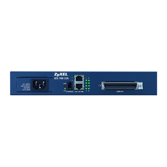
H A P T E R Front Panel This chapter describes the front panel of the IES-708-22A, shown below. Figure 7 Front Panel The LEDs and ports are discussed in the following sections. 3.1 LEDs The following table describes the LED indicators on the IES-708-22A. Table 1 LEDs COLOR STATUS... -
Page 50: Front Panel Ports
Chapter 3 Front Panel 3.2 Front Panel Ports The following table describes the port labels on the front panel. Table 2 Front Panel Ports LABEL DESCRIPTION POWER Connect an appropriate power source to the IES-708-22A. CONSOLE Only connect this port if you want to configure the IES-708-22A using the command line interface (CLI) via the console port. -
Page 51: User/Co Ports
Chapter 3 Front Panel 3.2.4 USER/CO Ports Use a Telco-50 connector to connect the USER/CO ports to other SHDSL devices. The rest of this section introduces Telco-50 cables, MDF (Main Distribution Frames), and explains how to connect the USER/CO ports to MDF. 3.2.4.1 Telco-50 Cables Telco-50 cables are used for data and voice applications with MDFs (Main Distribution Frame), patch panels and distribution boxes. -
Page 52: Figure 9 Mdf Wiring
Chapter 3 Front Panel Figure 9 MDF Wiring • Connect wiring from end-user equipment to the lower ports of an MDF using a telephone wire. Connect wiring from the telephone company to the upper ports of an MDF (see the previous figure). -
Page 53: Figure 10 Mdf Installation Scenario
Chapter 3 Front Panel Figure 10 MDF Installation Scenario 1 Connect the Telco-50 connector end of the cable to the Telco-50 connector. 2 Connect the USER/CO wiring on the other end of the Telco-50 cable to the upper ports of the MDF using a punch-down tool. 3 Connect the telephone wiring from each end-user's DSL modem to the lower ports of the MDF. - Page 54 Chapter 3 Front Panel IES-708-22A User’s Guide...
-
Page 55: Web Configurator
Web Configurator Introducing the Web Configurator (57) Initial Configuration (65) Home and Port Statistics Screens (71) System Information (83) General Setup (87) User Account (89) Switch Setup (93) IP Setup (99) ENET Port Setup (101) xDSL Port Setup (103) xDSL Profiles Setup (117) xDSL Line Data (131) G.bond (135) VLAN (139) - Page 56 DHCP Snoop (185) 2684 Routed Mode (189) PPPoA to PPPoE (197) DSCP (203) TLS PVC (205) ACL (209) Downstream Broadcast (215) SysLog (217) Access Control (219) Static Routing (227) Alarm (229) Maintenance (235) Diagnostic (239) MAC Table (241) ARP Table (243)
-
Page 57: Introducing The Web Configurator
H A P T E R Introducing the Web Configurator This chapter tells how to access and navigate the web configurator. 4.1 Introduction The web configurator is an HTML-based management interface that allows easy IES-708-22A setup and management via Internet browser. Use Internet Explorer 6.0 and later or Netscape Navigator 7.0 and later versions. -
Page 58: Status Screen
Chapter 4 Introducing the Web Configurator 3 The login screen appears. The default username is admin and associated default password is 1234. The date and time display as shown if you have not configured a time server nor manually entered a time and date in the General Setup screen. Figure 11 Login 4 Click OK to view the first web configurator screen. -
Page 59: Navigation Panel
Chapter 4 Introducing the Web Configurator B - Click this to open the Home screen. (This is the same screen that is displayed above.) See Chapter 6 on page 71 for more information. C - Click this to log out of the web configurator. 4.5 Navigation Panel In the navigation panel, click a menu item to reveal a list of submenu links. - Page 60 Chapter 4 Introducing the Web Configurator Table 4 Web Configurator Screens (continued) LABEL DESCRIPTION General Setup Use this screen to configure general identification information about the device and the time and date settings. User Account Use this screen to configure system administrator accounts. Switch Setup Use this screen to set up system-wide parameters such as MAC address learning and priority queues.
-
Page 61: Changing Your Password
Chapter 4 Introducing the Web Configurator Table 4 Web Configurator Screens (continued) LABEL DESCRIPTION Access Control Use this screen to configure service access control and configure SNMP and remote management. Routing Protocol Static Routing Use this screen to configure static routes. A static route defines how the IES- 708-22A should forward traffic by configuring the TCP/IP parameters manually. -
Page 62: Saving Your Configuration
Chapter 4 Introducing the Web Configurator Figure 14 User Account Enter the new password in the Password and Retype Password to confirm fields, and click Modify. Do not forget to click Config Save before you exit the web configurator. See Section 4.7 on page 4.7 Saving Your Configuration... -
Page 63: Figure 15 Logout
Chapter 4 Introducing the Web Configurator Figure 15 Logout IES-708-22A User’s Guide... - Page 64 Chapter 4 Introducing the Web Configurator IES-708-22A User’s Guide...
-
Page 65: Initial Configuration
H A P T E R Initial Configuration This chapter describes initial configuration for the IES-708-22A. See Chapter 57 on page 387 for various default settings of the IES-708-22A. 5.1 Initial Configuration Overview This chapter shows what you first need to do to provide service to DSL subscribers. 5.2 Initial Configuration This chapter uses the web configurator for initial configuration. -
Page 66: Figure 17 Xdsl Port Setup
Chapter 5 Initial Configuration If you change the IP address of the IES-708-22A, after you click Apply IP setting, you have to use the new IP address to log into the web configurator again. 4 If your subscribers use VPI 0 and VCI 33 (the default for all of the DSL ports), go to step 13. -
Page 67: Figure 18 Vc Setup
Chapter 5 Initial Configuration Figure 18 VC Setup 7 Select any virtual channel’s Select radio button, and click Delete. The following screen appears. Figure 19 VC Setup, Delete 8 Click OK. The following screen appears. Figure 20 Select Ports 9 Click All, and then click Apply. The VC Setup screen is updated. IES-708-22A User’s Guide... -
Page 68: Figure 21 Vc Setup
Chapter 5 Initial Configuration Figure 21 VC Setup 10 Select Super Channel to allow the channel to forward frames belonging to multiple VLAN groups (that are not assigned to other channels). Then, enter the VPI and VCI that you use. Leave the other default settings, and click Add. The VC Setup screen is updated. -
Page 69: Figure 23 Select Ports
Chapter 5 Initial Configuration Figure 23 Select Ports 12 Click All, and then click Apply. The VC Setup screen is updated. Figure 24 VC Setup 13 Click Config Save > Config Save. The Config Save screen appears. Figure 25 Config Save 14 Click Save. -
Page 70: Figure 26 Config Save > Save Successful
Chapter 5 Initial Configuration Figure 26 Config Save > Save Successful You can now use the device (with the other settings set to the defaults) to provide service to DSL subscribers. See Chapter 57 on page 387 for information on other default settings. IES-708-22A User’s Guide... -
Page 71: Home And Port Statistics Screens
H A P T E R Home and Port Statistics Screens This chapter describes the Home (status), Port Statistics, and RMON screens. 6.1 Home Screen The Home screen of the web configurator displays a port statistical summary with links to each port showing statistical details. -
Page 72: Ethernet Port Statistics Screen
Chapter 6 Home and Port Statistics Screens Table 5 Home (continued) LABEL DESCRIPTION Media This field displays the type of media that this Ethernet port is using for a connection. “-“ displays when the port is disabled or not connected. Duplex This field displays whether the port is using half or full-duplex communication. -
Page 73: Figure 28 Home > Port Statistics (Ethernet)
Chapter 6 Home and Port Statistics Screens Figure 28 Home > Port Statistics (Ethernet) The following table describes the labels in this screen. Table 6 Home > Port Statistics (Ethernet) LABEL DESCRIPTION RMON Click this to open the RMON Statistics screen. Click this to go back to the Home screen. - Page 74 Chapter 6 Home and Port Statistics Screens Table 6 Home > Port Statistics (Ethernet) (continued) LABEL DESCRIPTION Rx broadcast This field shows the number of good broadcast frames received of 64 to 1518 octets in length (for non VLAN) or 1522 octets (for VLAN), not including multicast frames.
-
Page 75: Dsl Port Statistics Screen
Chapter 6 Home and Port Statistics Screens Table 6 Home > Port Statistics (Ethernet) (continued) LABEL DESCRIPTION packet(<=64) This field shows the number of frames received and transmitted (including bad frames) that were 64 octets or less in length (this includes FCS octets but excludes framing bits). -
Page 76: Figure 29 Home > Port Statistics (Dsl)
Chapter 6 Home and Port Statistics Screens Figure 29 Home > Port Statistics (DSL) The following table describes the labels in this screen. Table 7 Home > Port Statistics (DSL) LABEL DESCRIPTION RMON Click this to open the RMON Statistics screen. Click this to go back to the Home screen. -
Page 77: Rmon Statistics Screen
Chapter 6 Home and Port Statistics Screens Table 7 Home > Port Statistics (DSL) (continued) LABEL DESCRIPTION Rx discard packets This field shows the number of received packets that were dropped on this port. Some of the possible reasons for the discarding of received (rx) packets are: •... -
Page 78: Figure 30 Home > Port Statistics > Rmon
Chapter 6 Home and Port Statistics Screens Figure 30 Home > Port Statistics > RMON The following table describes the labels in this screen. Table 8 Home > Port Statistics > RMON LABEL DESCRIPTION Port Statistics Click this to go back to the previous screen. Enet1 Click this to look at the RMON history for this port. -
Page 79: Rmon History Screen
Chapter 6 Home and Port Statistics Screens Table 8 Home > Port Statistics > RMON (continued) LABEL DESCRIPTION EtherStatsOversizePkts This field displays the total number of packets that were too big received/transmitted on this port. EtherStatsFragments This is the number of frames received/transmitted that were less than 64 octets long, and contained an invalid FCS, including non-integral and integral lengths. -
Page 80: Rmon History Detail Screen
Chapter 6 Home and Port Statistics Screens Figure 31 Home > Port Statistics > RMON > RMON History The following table describes the labels in this screen. Table 9 Home > Port Statistics > RMON > RMON History LABEL DESCRIPTION Index:Interval Select the index of the sample interval and the desired data sampling time (in seconds). -
Page 81: Figure 32 Home > Port Statistics > Rmon > Rmon History > Detail
Chapter 6 Home and Port Statistics Screens Figure 32 Home > Port Statistics > RMON > RMON History > Detail The following table describes the labels in this screen. Table 10 Home > Port Statistics > RMON > RMON History > Detail LABEL DESCRIPTION Click this to return to the previous screen. - Page 82 Chapter 6 Home and Port Statistics Screens Table 10 Home > Port Statistics > RMON > RMON History > Detail (continued) LABEL DESCRIPTION Jabbers This is the number of frames received/transmitted that were longer than 1518 octets (non VLAN) or 1522 octets (VLAN) and contained an invalid FCS, including alignment errors.
-
Page 83: System Information
H A P T E R System Information The System Information screen displays general device information (such as firmware version number) and hardware polling information (such as temperature status). You can check the firmware version number and monitor the hardware status in this screen. To open this screen, click Basic Setting >... -
Page 84: Table 11 Basic Setting > System Information
Chapter 7 System Information The following table describes the labels in this screen. Table 11 Basic Setting > System Information LABEL DESCRIPTION System Name This field displays the device's model name, including STU-R/STU-C mode. ZyNOS F/W Version This field displays the version number of the device’s current firmware including the date created. - Page 85 Chapter 7 System Information Table 11 Basic Setting > System Information (continued) LABEL DESCRIPTION Temperature (Hi) Use these fields to configure the highest temperature limit at each sensor. Temperature (Lo) Use these fields to configure the lowest temperature limit at each sensor. Volt.
- Page 86 Chapter 7 System Information IES-708-22A User’s Guide...
-
Page 87: General Setup
H A P T E R General Setup The General Setup screen allows you to configure general device identification information. It also allows you to set the system time manually or get the current time and date from an external server when you turn on your device. The real time is then displayed in the logs. To open this screen, click Basic Setting >... - Page 88 Chapter 8 General Setup Table 12 Basic Setting > General Setup (continued) LABEL DESCRIPTION Use Time Server Select the time service protocol that the timeserver uses. Not all time servers When Bootup support all protocols, so you may have to use trial and error to find a protocol that works.
-
Page 89: User Account
H A P T E R User Account The User Account screens allows you to set up and configure system administrator accounts for the IES-708-22A. You can also configure the authentication policy for IES-708-22A administrators. This is different than port authentication in Chapter 24 on page 175. -
Page 90: Authentication Screen
Chapter 9 User Account Table 13 Basic Setting > User Account (continued) LABEL DESCRIPTION Privilege Select a privilege level to determine which screens the administrator can use. There is a high, medium or low privilege level for each command. Select high to allow the administrator to use all commands including the lower privilege commands. -
Page 91: Table 14 Basic Setting > User Account > Authentication
Chapter 9 User Account The following table describes the labels in this screen. Table 14 Basic Setting > User Account > Authentication LABEL DESCRIPTION User account Click this to open the User Account screen. See Section 9.1 on page Authentication Mode Select the process by which the IES-708-22A authenticates administrators. local - Search the local database. - Page 92 Chapter 9 User Account IES-708-22A User’s Guide...
-
Page 93: Switch Setup
H A P T E R Switch Setup The Switch Setup screen allows you to set up and configure global device features. 10.1 GARP Timer Setup GARP (Generic Attribute Registration Protocol) allows network devices to register and de- register attribute values with other GARP participants within a bridged LAN. GARP is a protocol that provides a generic mechanism for protocols that serve a more specific application, for example, GVRP (GARP VLAN Registration Protocol). -
Page 94: Port Isolation With Standalone Switch Mode Example
Chapter 10 Switch Setup 10.2.2 Port Isolation with Standalone Switch Mode Example The following graphic shows IES-708-22A 1 and 2 connected to each other and the Ethernet backbone switch (3) in a network topology that creates a loop. The IES-708-22A are using the standalone switch mode and have RSTP enabled. -
Page 95: Switch Setup Screen
Chapter 10 Switch Setup With port isolation turned on, communications between A and B must first go through another switch or router (3 in the figure). A and B also cannot communicate with C without their communications going through another switch or router. Figure 38 Port Isolation with Daisychain Switch Mode Example 10.3 Switch Setup Screen To open this screen, click Basic Setting >... -
Page 96: Figure 39 Basic Setting > Switch Setup
Chapter 10 Switch Setup Figure 39 Basic Setting > Switch Setup The following table describes the labels in this screen. Table 15 Basic Setting > Switch Setup LABEL DESCRIPTION MAC Address Enter a time from 10 to 10,000 seconds. This is how long all dynamically Learning learned MAC addresses remain in the MAC address table before they age out (and must be relearned). - Page 97 Chapter 10 Switch Setup Table 15 Basic Setting > Switch Setup (continued) LABEL DESCRIPTION MAC Anti-Spoofing (STU-C mode only) Select this if you want the IES-708-22A to generate an alarm and issue a SNMP trap when an existing MAC address appears on another port.
- Page 98 Chapter 10 Switch Setup IES-708-22A User’s Guide...
-
Page 99: Ip Setup
H A P T E R IP Setup The IP Setup screen allows you to configure a device IP address, subnet mask and DNS (domain name server) for management purposes. To open this screen, click Basic Setting > IP Setup. Figure 40 Basic Setting >... - Page 100 Chapter 11 IP Setup IES-708-22A User’s Guide...
-
Page 101: Enet Port Setup
H A P T E R ENET Port Setup The ENET Port Setup screen allows you to configure settings for the Ethernet ports. To open this screen, click Basic Setting > ENET Port Setup. Figure 41 Basic Setting > ENET Port Setup The following table describes the labels in this screen. - Page 102 Chapter 12 ENET Port Setup IES-708-22A User’s Guide...
-
Page 103: Xdsl Port Setup
H A P T E R xDSL Port Setup This chapter explains how to configure settings for profiles and individual DSL ports. It also covers how to configure virtual channels and virtual channel profiles. 13.1 DSL Profiles A DSL profile is a table that contains a list of pre-configured DSL settings. Each DSL port has one (and only one) profile assigned to it at any given time. -
Page 104: Xdsl Port Setup Screen
Chapter 13 xDSL Port Setup Chapter 57 on page 387 for the settings of the default profile and DSL port default settings. 13.5 xDSL Port Setup Screen To open this screen, click Basic Setting > xDSL Port Setup. Figure 42 Basic Setting > xDSL Port Setup The following table describes the labels in this screen. -
Page 105: Xdsl Port Setting Screen
Chapter 13 xDSL Port Setup Table 18 Basic Setting > xDSL Port Setup (continued) LABEL DESCRIPTION Active Select this check box to copy this port’s active setting. This is configured in the xDSL Port Setting screen (see Section 13.5.1 on page 105). -
Page 106: Figure 44 Basic Setting > Xdsl Port Setup > Xdsl Port Setting
Chapter 13 xDSL Port Setup Figure 44 Basic Setting > xDSL Port Setup > xDSL Port Setting The following table describes the labels in this screen. Table 19 Basic Setting > xDSL Port Setup > xDSL Port Setting LABEL DESCRIPTION Last Page Click this to return to the previous screen. -
Page 107: Virtual Channels
Chapter 13 xDSL Port Setup Table 19 Basic Setting > xDSL Port Setup > xDSL Port Setting (continued) LABEL DESCRIPTION Stur Alarm Profile Select an alarm profile to define the thresholds that trigger an alarm on the port when exceeded. This alarm profile is for the STU-R (SHDSL Termination Unit - Remote) end point. -
Page 108: Super Channel
Chapter 13 xDSL Port Setup Use the Edit Static VLAN screen to configure a static VLAN on the IES-708-22A for voice on the port. Use the DSL Edit Port Channel Setup screen to: • Configure a channel on the port for voice service. •... -
Page 109: Figure 45 Basic Setting > Xdsl Port Setup > Vc Setup
Chapter 13 xDSL Port Setup Figure 45 Basic Setting > xDSL Port Setup > VC Setup The following table describes the labels in this screen. Table 20 Basic Setting > xDSL Port Setup > VC Setup LABEL DESCRIPTION xDSL Port Setup Click xDSL Port Setup to go to the screen where you can configure DSL port settings (see Section 13.5 on page... - Page 110 Chapter 13 xDSL Port Setup Table 20 Basic Setting > xDSL Port Setup > VC Setup (continued) LABEL DESCRIPTION PVID Type a PVID (Port VLAN ID) to assign to untagged frames received on this channel. Priority Use the drop-down list box to select the priority value (0 to 7) to add to incoming frames without a (IEEE 802.1p) priority tag.
-
Page 111: Figure 46 Basic Setting, Xdsl Port Setup, Vc Setup, Delete
Chapter 13 xDSL Port Setup Table 20 Basic Setting > xDSL Port Setup > VC Setup (continued) LABEL DESCRIPTION Select Do the following to remove one or more PVCs. Delete 1. Select a PVC’s Select radio button. 2. Click Delete. 3. -
Page 112: Priority-Based Pvcs
Chapter 13 xDSL Port Setup Table 20 Basic Setting > xDSL Port Setup > VC Setup (continued) LABEL DESCRIPTION Select Do the following to copy settings from one PVC to another port or ports. Copy 1. Click the Select radio button of the PVC from which you want to copy settings. -
Page 113: Ppvc Setup Screen
Chapter 13 xDSL Port Setup 13.9 PPVC Setup Screen Use this screen to view and configure PPVCs. To open this screen, click Basic Setting > xDSL Port Setup > PPVC Setup. Figure 49 Basic Setting > xDSL Port Setup > PPVC Setup The following table describes the labels in this screen. -
Page 114: Ppvc Setup Members Screen
Chapter 13 xDSL Port Setup Table 22 Basic Setting > xDSL Port Setup > PPVC Setup (continued) LABEL DESCRIPTION Show Port Select the number of a DSL port for which to display PPVC settings (or display all of them). Index This field displays the number of the PPVC. -
Page 115: Table 23 Basic Setting > Xdsl Port Setup > Ppvc Setup > Edit
Chapter 13 xDSL Port Setup The following table describes the labels in this screen. Table 23 Basic Setting > xDSL Port Setup > PPVC Setup > Edit LABEL DESCRIPTION Port This is the port for which you are viewing or configuring settings. Index This field displays the number of the member PVC. - Page 116 Chapter 13 xDSL Port Setup IES-708-22A User’s Guide...
-
Page 117: Xdsl Profiles Setup
H A P T E R xDSL Profiles Setup A profile is a list of settings that you define. Then you can assign them to one or more individual ports. For background information about many of these settings, see Chapter 13 on page 103. -
Page 118: Port Profile Screen
Chapter 14 xDSL Profiles Setup 14.3 Port Profile Screen To open this screen, click Basic Setting > xDSL Profiles Setup. Figure 51 Basic Setting > xDSL Profiles Setup The following table describes the labels in this screen. Table 24 Basic Setting > xDSL Profiles Setup LABEL DESCRIPTION VC Profile... -
Page 119: Atm Qos
Chapter 14 xDSL Profiles Setup Table 24 Basic Setting > xDSL Profiles Setup (continued) LABEL DESCRIPTION Min Rate Type the minimum upstream transfer rate for this profile. Annex Mode Select the region setting. Select annex_a to use DSL over POTS (G.992.1 Annex A). Select annex_b to use DSL over ISDN (G.992.1 Annex B). -
Page 120: Atm Traffic Classes
Chapter 14 xDSL Profiles Setup Traffic shaping controls outgoing (downstream) traffic, not incoming (upstream). 14.5.1 ATM Traffic Classes These are the basic ATM traffic classes defined by the ATM Forum Traffic Management 4.0 Specification. 14.5.1.1 Constant Bit Rate (CBR) Constant Bit Rate (CBR) is an ATM traffic class that provides fixed bandwidth. CBR traffic is generally time-sensitive (doesn’t tolerate delay). -
Page 121: Figure 52 Pcr, Scr And Mbs In Traffic Shaping
Chapter 14 xDSL Profiles Setup 14.5.2.2 Sustained Cell Rate (SCR) Sustained Cell Rate (SCR) is the mean cell rate of each bursty traffic source. It specifies the maximum average rate at which cells can be sent over the virtual connection. SCR may not be greater than the PCR. -
Page 122: Upstream Policing
Chapter 14 xDSL Profiles Setup Figure 53 TAT, CDVT and BT in Traffic Shaping 14.6 Upstream Policing Upstream policing is an agreement between the carrier and the subscriber to regulate the average rate and fluctuations of data transmission coming from the subscriber's device to the IES-708-22A. -
Page 123: Vc Profile Screen
Chapter 14 xDSL Profiles Setup 14.7 VC Profile Screen To open this screen, click Basic Setting >xDSL Profiles Setup > VC Profile. Figure 54 Basic Setting > xDSL Profiles Setup > VC Profile The following table describes the labels in this screen. Table 25 Basic Setting >... -
Page 124: Alarm Profile Screen
Chapter 14 xDSL Profiles Setup Table 25 Basic Setting > xDSL Profiles Setup > VC Profile (continued) LABEL DESCRIPTION The rest of the screen is for PVC configuration. Name When editing a profile, this is the name of this profile. When adding a profile, type a name for the profile. -
Page 125: Figure 55 Basic Setting > Xdsl Profiles Setup > Alarm Profile
Chapter 14 xDSL Profiles Setup Figure 55 Basic Setting > xDSL Profiles Setup > Alarm Profile The following table describes the labels in this screen. Table 26 Basic Setting > xDSL Profiles Setup > Alarm Profile LABEL DESCRIPTION Port Profile Click Port Profile to open the Port Profile screen (see Section 14.3 on page 118). -
Page 126: Alarm Profile Map Screen
Chapter 14 xDSL Profiles Setup Table 26 Basic Setting > xDSL Profiles Setup > Alarm Profile (continued) LABEL DESCRIPTION The number of UnAvailable Seconds (0~900) that are permitted to occur within 15 minutes. Index This is the index number of the alarm profile. Name This is the name of the alarm profile. -
Page 127: Igmp Filtering
Chapter 14 xDSL Profiles Setup Table 27 Basic Setting > xDSL Profiles Setup > Alarm Profile > Map (continued) LABEL DESCRIPTION Span This field displays whether or not the alarm profile is assigned to this port as the alarm profile for the whole span. It displays V if it is assigned, and it displays - if it is not assigned. -
Page 128: Figure 57 Basic Setting > Xdsl Profiles Setup > Igmp Filter Profile
Chapter 14 xDSL Profiles Setup Figure 57 Basic Setting > xDSL Profiles Setup > IGMP Filter Profile The following table describes the labels in this screen. Table 28 Basic Setting > xDSL Profiles Setup > IGMP Filter Profile LABEL DESCRIPTION Port Profile Click Port Profile to configure port profiles and assign them to individual ports (see... - Page 129 Chapter 14 xDSL Profiles Setup Table 28 Basic Setting > xDSL Profiles Setup > IGMP Filter Profile (continued) LABEL DESCRIPTION End IP Enter the ending multicast IP address for a range of IP addresses to which you want this IGMP filter profile to allow access. If you want to add a single multicast IP address, enter it in both the Start IP and End IP fields.
- Page 130 Chapter 14 xDSL Profiles Setup IES-708-22A User’s Guide...
-
Page 131: Xdsl Line Data
H A P T E R xDSL Line Data 15.1 xDSL Line Rate Info Screen This screen displays a DSL port’s line operating values. Information obtained prior to training to steady state transition will not be valid or will be old information. To open this screen, click Basic Setting >... -
Page 132: Xdsl Performance Screen
Chapter 15 xDSL Line Data Table 29 Basic Setting > xDSL Line Data (continued) LABEL DESCRIPTION Actual This is the rate (in Kbps) at which the port has been sending and receiving data. Rate(kbps) Noise This is the DSL line’s noise margin measured in decibels (dB). Margin(dB) Attenuation(dB) This is the reduction in amplitude of the DSL signals, measured in decibels (dB). -
Page 133: Figure 59 Basic Setting > Xdsl Line Data > Line Performance
Chapter 15 xDSL Line Data Figure 59 Basic Setting > xDSL Line Data > Line Performance The following table describes the labels in this screen. Table 30 Basic Setting > xDSL Line Data > Line Performance LABEL DESCRIPTION Line Rate Click Line Rate to display a DSL port’s line operating values (see Section 15.1 on page... - Page 134 Chapter 15 xDSL Line Data Table 30 Basic Setting > xDSL Line Data > Line Performance (continued) LABEL DESCRIPTION Stuc/Stur SES The number of Severely Errored Seconds detected by the STU-C and the STU- R on this DSL port. A Severely Errored Second is defined as a count of 1- second intervals during which at least 50 CRC anomalies are declared or one or more LOSW defects are declared.
-
Page 135: G.bond
H A P T E R G.bond This chapter explains how to combine multiple ports into a logical link. 16.1 Bonding Overview Bonding combines multiple ports into a logical link. This lets the IES-708-22A transmit at higher bandwidths over longer distances. In addition, bonding is a cheaper alternative than installing fiber. -
Page 136: Figure 60 Basic Setting > G.bond
Chapter 16 G.bond Figure 60 Basic Setting > G.bond The following table describes the labels in this screen. Table 31 Basic Setting > G.bond LABEL DESCRIPTION G.bond Status Click G.bond Status to look at the status of each port in each bond (see Section 16.2.1 on page 137). -
Page 137: G.bond Status Screen
Chapter 16 G.bond Table 31 Basic Setting > G.bond (continued) LABEL DESCRIPTION Select this to add or update the bond. Apply Cancel Select this to clear the fields in this screen without saving any changes. 16.2.1 G.bond Status Screen Use this screen to look at the status of each port in each bond. To open this screen, click Basic Setting >... - Page 138 Chapter 16 G.bond IES-708-22A User’s Guide...
-
Page 139: Vlan
H A P T E R VLAN This chapter shows you how to configure IEEE 802.1Q tagged VLANs. 17.1 Introduction to VLANs A VLAN (Virtual Local Area Network) allows a physical network to be partitioned into multiple logical networks. Devices on a logical network belong to one group. A device can belong to more than one group. -
Page 140: Forwarding Tagged And Untagged Frames
Chapter 17 VLAN priority frame, meaning that only the priority level is significant and the default VID of the ingress port is given as the VID of the frame. Of the 4096 possible VIDs, a VID of 0 is used to identify priority frames and value 4095 (FFF) is reserved, so the maximum possible VLAN configurations are 4,094. -
Page 141: Figure 62 Advanced Application > Vlan
Chapter 17 VLAN Figure 62 Advanced Application > VLAN The following table describes the labels in this screen. Table 33 Advanced Application > VLAN LABEL DESCRIPTION Static VLAN Setting Click Static VLAN Setting to configure ports to dynamically join a VLAN group or permanently assign ports to a VLAN group or prohibit ports from joining a VLAN group (see Section 17.4 on page... -
Page 142: Static Vlan Setting Screen
Chapter 17 VLAN Table 33 Advanced Application > VLAN (continued) LABEL DESCRIPTION Stop Click Stop to halt polling statistics. Previous Page Click one of these buttons to show the preceding/following screen if the information cannot be displayed in one screen. Next Page 17.4 Static VLAN Setting Screen You can assign a port to be a member of a VLAN group or prohibit a port from joining a... -
Page 143: Vlan Port Setting Screen
Chapter 17 VLAN Table 34 Advanced Application > VLAN > Static VLAN Setting (continued) LABEL DESCRIPTION Name This field displays the descriptive name for this VLAN group. Delete Select the check boxes of the rule(s) that you want to remove in the Delete column and then click the Delete button. -
Page 144: Figure 64 Advanced Application > Vlan > Vlan Port Setting
Chapter 17 VLAN Figure 64 Advanced Application > VLAN > VLAN Port Setting The following table describes the labels in this screen. Table 35 Advanced Application > VLAN > VLAN Port Setting LABEL DESCRIPTION VLAN Status Click VLAN Status to see which of the IES-708-22A’s ports are members of which VLANs (see Section 17.3 on page 140). -
Page 145: Figure 65 Select Ports
Chapter 17 VLAN Table 35 Advanced Application > VLAN > VLAN Port Setting (continued) LABEL DESCRIPTION Cancel Click Cancel to begin configuring this screen afresh. Copy port Do the following to copy settings from one port to another port or ports. Paste 1. - Page 146 Chapter 17 VLAN IES-708-22A User’s Guide...
-
Page 147: Igmp
H A P T E R IGMP This chapter describes the IGMP screens. 18.1 IGMP Traditionally, IP packets are transmitted in one of either two ways - Unicast (1 sender to 1 recipient) or Broadcast (1 sender to everybody on the network). Multicast delivers IP packets to just a group of hosts on the network. -
Page 148: Igmp Status Screen
Chapter 18 IGMP In IGMP proxy, an upstream interface is the port that is closer to the source (or the root of the multicast tree) and is able to receive multicast traffic. There should only be one upstream interface (also known as the query port) for one query VLAN on the IES-708-22A. A downstream interface is a port that connects to a host (such as a computer). -
Page 149: Figure 67 Advanced Application > Igmp
Chapter 18 IGMP Figure 67 Advanced Application > IGMP The following table describes the labels in this screen. Table 36 Advanced Application > IGMP LABEL DESCRIPTION Bandwidth Setup (STU-C mode only) Click Bandwidth Setup to open the IGMP Bandwidth screen where you can set up bandwidth requirements for multicast channels (see Section 18.4 on page 150). -
Page 150: Igmp Bandwidth Screen
Chapter 18 IGMP Table 36 Advanced Application > IGMP (continued) LABEL DESCRIPTION Index This is the IGMP group index number. The VID is the VLAN ID on which the IGMP group is created. IP Address This is the IP address of an IP multicast group member. 1~8, enet1, enet2 These columns indicate whether or not each port is a member of the IGMP snooping group. -
Page 151: Bandwidth Port Setup Screen
Chapter 18 IGMP Table 37 Advanced Application > IGMP > Bandwidth Setup (continued) LABEL DESCRIPTION Index Select a unique number for this setting. If you select a number that is already used, the new setting overwrites the old one when you click Apply. Start Multicast IP Enter the beginning of the multicast range. -
Page 152: Igmp Setup Screen
Chapter 18 IGMP The following table describes the labels in this screen. Table 38 Advanced Application > IGMP > Bandwidth Setup > Port Setup LABEL DESCRIPTION Bandwidth Setup Click Bandwidth Setup to open the IGMP Bandwidth screen where you can set up bandwidth requirements for multicast channels (see Section 18.4 on page... -
Page 153: Igmp Filter Setup Screen
Chapter 18 IGMP Table 39 Advanced Application > IGMP > IGMP Setup (continued) LABEL DESCRIPTION IGMP Mode (STU-R mode only) Select Enable to have the device use IGMP snooping. Select Disable to have the device not use IGMP snooping. (STU-C mode only) Select Proxy to have the device use IGMP proxy. -
Page 154: Igmp Port Info Screen
Chapter 18 IGMP Figure 71 Advanced Application > IGMP > Count Setup The following table describes the labels in this screen. Table 40 Advanced Application > IGMP > Count Setup LABEL DESCRIPTION IGMP Status Click IGMP Status to open the IGMP Setup screen where you can view current IGMP information (see Section 18.3 on page 148). -
Page 155: Igmp Port Group Screen
Chapter 18 IGMP The following table describes the labels in this screen. Table 41 Advanced Application > IGMP > IGMP Port Info LABEL DESCRIPTION IGMP Status Click IGMP Status to open the IGMP Setup screen where you can view current IGMP information (see Section 18.3 on page 148). - Page 156 Chapter 18 IGMP IES-708-22A User’s Guide...
-
Page 157: Static Multicast
H A P T E R Static Multicast This chapter describes the Static Multicast screen. 19.1 Static Multicast Use static multicast to allow incoming frames based on multicast MAC address(es) that you specify. This feature can be used in conjunction with IGMP snooping to allow multicast MAC address(es) that are not learned by IGMP snooping. - Page 158 Chapter 19 Static Multicast Table 43 Advanced Application > Static Multicast (continued) LABEL DESCRIPTION Index This is the static multicast group index number. MAC Address This is the multicast MAC address. These fields display the static multicast group membership status of the DSL ports.
-
Page 159: Multicast Vlan
H A P T E R Multicast VLAN This feature is available in STU-C mode only. This chapter describes the Multicast VLAN screens. 20.1 Multicast VLAN Overview Multicast VLAN allows one single multicast VLAN to be shared among different subscriber VLANs on the network. -
Page 160: Mvlan Setup Screen
Chapter 20 Multicast VLAN The following table describes the labels in this screen. Table 44 Advanced Application > Multicast VLAN LABEL DESCRIPTION MVLAN Setup Click MVLAN Setup to open the MVLAN Setup screen where you can configure basic settings and port members for each multicast VLAN (see Section 20.3 on page 160). -
Page 161: Figure 76 Advanced Application > Multicast Vlan > Mvlan Setup
Chapter 20 Multicast VLAN Figure 76 Advanced Application > Multicast VLAN > MVLAN Setup The following table describes the labels in this screen. Table 45 Advanced Application > Multicast VLAN > MVLAN Setup LABEL DESCRIPTION MVLAN Status Click MVLAN Status to open the MVLAN Status screen where you can view a summary of all multicast VLAN on the IES-708-22A (see Section 20.2 on page 159). -
Page 162: Mvlan Group Screen
Chapter 20 Multicast VLAN Table 45 Advanced Application > Multicast VLAN > MVLAN Setup (continued) LABEL DESCRIPTION Control Select Fixed for the port to be a permanent member of this multicast VLAN. Use the Select All button to include every port. Select Forbidden if you want to prohibit the port from joining this multicast VLAN. - Page 163 Chapter 20 Multicast VLAN Table 46 Advanced Application > Multicast VLAN > MVLAN Group (continued) LABEL DESCRIPTION MVLAN ID Select the VLAN ID of the multicast VLAN for which you want to configure a range of multicast IP addresses. Index Select the index number of the multicast VLAN group (the range of multicast IP addresses) you want to configure for this multicast VLAN.
- Page 164 Chapter 20 Multicast VLAN IES-708-22A User’s Guide...
-
Page 165: Packet Filtering
H A P T E R Packet Filtering This feature is available in STU-C mode only. This chapter describes how to configure the Packet Filter screen. 21.1 Packet Filter Screen Use this screen to set which types of packets the IES-708-22A accepts on individual DSL ports. - Page 166 Chapter 21 Packet Filtering Table 47 Advanced Application > Filtering (continued) LABEL DESCRIPTION PPPoE Pass Point-to-Point Protocol over Ethernet relies on PPP and Ethernet. It is a through specification for connecting the users on an Ethernet to the Internet through a common broadband medium, such as a single DSL line, wireless device or cable modem.
-
Page 167: Mac Filter
H A P T E R MAC Filter This feature is available in STU-C mode only. This chapter introduces the MAC filter. 22.1 MAC Filter Introduction Use the MAC filter to control from which MAC (Media Access Control) addresses frames can (or cannot) come in through a port. -
Page 168: Table 48 Advanced Application > Mac Filter
Chapter 22 MAC Filter The following table describes the labels in this screen. Table 48 Advanced Application > MAC Filter LABEL DESCRIPTION Port Use this drop-down list box to select a DSL port for which you wish to configure MAC filtering. Type a device’s MAC address in hexadecimal notation (xx:xx:xx:xx:xx:xx, where x is a number from 0 to 9 or a letter from a to f) in this field. -
Page 169: Spanning Tree Protocol
H A P T E R Spanning Tree Protocol This feature is available in STU-C mode only. This chapter introduces the Spanning Tree Protocol (STP) and Rapid Spanning Tree Protocol (RSTP). 23.1 RSTP and STP RSTP adds rapid reconfiguration capability to STP. The IES-708-22A supports RSTP and the earlier STP. -
Page 170: Figure 80 Stp Root Ports And Designated Ports
Chapter 23 Spanning Tree Protocol After a bridge determines the lowest cost-spanning tree with RSTP, it enables the root port and the ports that are the designated ports for the connected LANs, and disables all other ports that participate in RSTP. Network packets are therefore only forwarded between enabled ports, eliminating any possible network loops. -
Page 171: Spanning Tree Protocol Status Screen
Chapter 23 Spanning Tree Protocol Table 50 RSTP Port States (continued) RSTP PORT STATE STP PORT STATE DESCRIPTION Learning Learning All BPDUs are received and processed. Information frames are submitted to the learning process but not forwarded. Forwarding Forwarding All BPDUs are received and processed. All information frames are received and forwarded. - Page 172 Chapter 23 Spanning Tree Protocol Table 51 Advanced Application > Spanning Tree Protocol (continued) LABEL DESCRIPTION Bridge Status If STP is activated, the following fields appear. If STP is not activated, Disabled appears. Our bridge ID This is the unique identifier for this bridge, consisting of bridge priority plus MAC address.
-
Page 173: Spanning Tree Protocol Screen
Chapter 23 Spanning Tree Protocol Table 51 Advanced Application > Spanning Tree Protocol (continued) LABEL DESCRIPTION Poll Interval(s) The text box displays how often (in seconds) this screen refreshes. You may change the refresh interval by typing a new number in the text box and then Set Interval clicking Set Interval. - Page 174 Chapter 23 Spanning Tree Protocol Table 52 Advanced Application > Spanning Tree Protocol > STP Config (continued) LABEL DESCRIPTION Hello Time This is the time interval in seconds between BPDU (Bridge Protocol Data Units) configuration message generations by the root switch. The allowed range is 1 to 10 seconds.
-
Page 175: Port Authentication
H A P T E R Port Authentication This feature is available in STU-C mode only. This chapter describes the 802.1x authentication method and RADIUS server connection setup. 24.1 Introduction to Authentication IEEE 802.1x is an extended authentication protocol that allows support of RADIUS (Remote Authentication Dial In User Service, RFC 2138, 2139) for centralized user profile management on a network RADIUS server. -
Page 176: Radius Screen
Chapter 24 Port Authentication 24.2 RADIUS Screen To open this screen, click Advanced Application > Port Authentication. Figure 84 Advanced Application > Port Authentication The following table describes the labels in this screen. Table 53 Advanced Application > Port Authentication LABEL DESCRIPTION 802.1x... -
Page 177: Screen
Chapter 24 Port Authentication Table 53 Advanced Application > Port Authentication (continued) LABEL DESCRIPTION Retype Password to Type the password again to make sure you have entered it properly. confirm Click Add to save your changes to the IES-708-22A’s volatile memory. The IES- 708-22A loses these changes if it is turned off or loses power, so use the Config Save link on the navigation panel to save your changes to the non-volatile memory when you are done configuring. - Page 178 Chapter 24 Port Authentication Table 54 Advanced Application > Port Authentication > 802.1x (continued) LABEL DESCRIPTION Cancel Click Cancel to begin configuring this screen afresh. Port This field displays a port number. Enable Select this check box to turn on IEEE 802.1x authentication on this port. Control Select AUTO to authenticate all subscribers before they can access the network through this port.
-
Page 179: Port Security
H A P T E R Port Security This feature is available in STU-C mode only. This chapter shows you how to set up port security. 25.1 Port Security Overview Port security allows you to restrict the number of MAC addresses that can be learned on a port. 25.2 Port Security Screen To open this screen, click Advanced Application >... -
Page 180: Figure 87 Select Ports
Chapter 25 Port Security Table 55 Advanced Application > Port Security (continued) LABEL DESCRIPTION Apply Click Apply to save your changes to the IES-708-22A’s volatile memory. The IES-708-22A loses these changes if it is turned off or loses power, so use the Config Save link on the navigation panel to save your changes to the non- volatile memory when you are done configuring. -
Page 181: Dhcp Relay
H A P T E R DHCP Relay This feature is available in STU-C mode only. This chapter shows you how to set up DHCP relays for each VLAN. 26.1 DHCP Relay DHCP (Dynamic Host Configuration Protocol, RFC 2131 and RFC 2132) allows individual clients to obtain TCP/IP configuration at start-up from a DHCP server. -
Page 182: Dhcp Relay Screen
Chapter 26 DHCP Relay Figure 88 DHCP Relay Agent Circuit ID Sub-option Format The Agent Information field that the IES-708-22A adds also contains an “Agent Remote-ID sub-option” of information that you specify. The following figure shows the format of the Agent Remote ID sub-option. The 2 in the first field identifies this as an Agent Remote ID sub-option. -
Page 183: Figure 90 Advanced Application > Dhcp Relay
Chapter 26 DHCP Relay Figure 90 Advanced Application > DHCP Relay The following table describes the labels in this screen. Table 56 Advanced Application > DHCP Relay LABEL DESCRIPTION Enable DHCP Enable DHCP relay to have the IES-708-22A relay DHCP requests to a DHCP Relay: server and the server’s responses back to the clients. - Page 184 Chapter 26 DHCP Relay Table 56 Advanced Application > DHCP Relay (continued) LABEL DESCRIPTION Apply Click Apply to save your changes to the IES-708-22A’s volatile memory. The IES-708-22A loses these changes if it is turned off or loses power, so use the Config Save link on the navigation panel to save your changes to the non- volatile memory when you are done configuring.
-
Page 185: Dhcp Snoop
H A P T E R DHCP Snoop This feature is available in STU-C mode only. This chapter shows you how to set up DHCP snooping settings on the subscriber ports. 27.1 DHCP Snoop Overview DHCP snooping prevents clients from assigning their own IP addresses. The IES-708-22A can store every (DSL port, MAC address, IP address) tuple offered by the DHCP server. -
Page 186: Dhcp Snoop Status Screen
Chapter 27 DHCP Snoop Table 57 Advanced Application > DHCP Snoop (continued) LABEL DESCRIPTION Select Select this, and click Active or Inactive to enable or disable the DHCP snooping on this port. Active Click this to enable DHCP snooping on the selected ports. Inactive Click this to disable DHCP snooping on the selected ports. -
Page 187: Dhcp Counter Screen
Chapter 27 DHCP Snoop 27.4 DHCP Counter Screen Use this screen to look at a summary of the DHCP packets on each port. To open this screen, click Advanced Application > DHCP Snoop > DHCP Counter. Figure 93 Advanced Application > DHCP Snoop > DHCP Counter The following table describes the labels in this screen. - Page 188 Chapter 27 DHCP Snoop IES-708-22A User’s Guide...
-
Page 189: 2684 Routed Mode
H A P T E R 2684 Routed Mode This feature is available in STU-C mode only. This chapter shows you how to set up 2684 routed mode service. 28.1 2684 Routed Mode Use the 2684 (formerly 1483) routed mode to have the IES-708-22A add MAC address headers to 2684 routed mode traffic from a PVC that connects to a subscriber device that uses 2684 routed mode. -
Page 190: 2684 Routed Pvc Screen
Chapter 28 2684 Routed Mode WAN IP address is 192.168.10.200. The routed domain is the LAN IP addresses behind the CPE device. The CPE device’s LAN IP address is 10.10.10.10 and the LAN computer’s IP address is 10.10.10.1. This includes the CPE device’s LAN IP addresses and the IP addresses of the LAN computers. -
Page 191: Figure 95 Advanced Application > 2684 Routed Pvc
Chapter 28 2684 Routed Mode To open this screen, click Advanced Application > 2684 Routed Mode. Figure 95 Advanced Application > 2684 Routed PVC The following table describes the labels in this screen. Table 60 Advanced Application > 2684 Routed PVC LABEL DESCRIPTION Routed Domain... -
Page 192: 2684 Routed Domain Screen
Chapter 28 2684 Routed Mode Table 60 Advanced Application > 2684 Routed PVC (continued) LABEL DESCRIPTION Port This field displays the number of the DSL port on which the routed PVC is configured. This field displays the Virtual Path Identifier (VPI) The VPI and VCI identify a channel on this port. -
Page 193: Rpvc Arp Proxy Screen
Chapter 28 2684 Routed Mode The following table describes the labels in this screen. Table 61 Advanced Application > 2684 Routed Mode > Routed Domain LABEL DESCRIPTION RPVC ARP Proxy Click RPVC ARP Proxy to go to the screen where you can view the Address Resolution Protocol table of IP addresses of CPE devices using 2684 routed mode and configure how long the device is to store them (see Section 28.4 on... -
Page 194: 2684 Routed Gateway Screen
Chapter 28 2684 Routed Mode To open this screen, click Advanced Application > 2684 Routed Mode > RPVC ARP Proxy. Figure 97 Advanced Application > 2684 Routed Mode > RPVC Arp Proxy The following table describes the labels in this screen. Table 62 Advanced Application >... -
Page 195: Figure 98 Advanced Application > 2684 Routed Mode > Routed Gateway
Chapter 28 2684 Routed Mode Figure 98 Advanced Application > 2684 Routed Mode > Routed Gateway The following table describes the labels in this screen. Table 63 Advanced Application > 2684 Routed Mode > Routed Gateway LABEL DESCRIPTION Routed PVC Click Routed PVC to go to the screen where you can configure routed PVC settings (see Section 28.2 on page... - Page 196 Chapter 28 2684 Routed Mode IES-708-22A User’s Guide...
-
Page 197: Pppoa To Pppoe
H A P T E R PPPoA to PPPoE This feature is available in STU-C mode only. This chapter shows you how to set up the IES-708-22A to convert PPPoA frames to PPPoE traffic and vice versa. 29.1 PPPoA to PPPoE Overview Before migrating to an Ethernet infrastructure, a broadband network might consist of PPPoA connections between the CPE devices and the DSLAM and PPPoE connections from the DSLAM to the Broadband Remote Access Server (BRAS). -
Page 198: Figure 100 Advanced Application > Pppoa To Pppoe
Chapter 29 PPPoA to PPPoE Figure 100 Advanced Application > PPPoA to PPPoE The following table describes the labels in this screen. Table 64 Advanced Application > PPPoA to PPPoE LABEL DESCRIPTION Port Use this drop-down list box to select a port for which you wish to set up PPPoA to PPPoE conversions. - Page 199 Chapter 29 PPPoA to PPPoE Table 64 Advanced Application > PPPoA to PPPoE (continued) LABEL DESCRIPTION AC Name This field is optional. Specify the hostname of a remote access concentrator if there are two access concentrators (or BRAS) on the network or if you want to allow PAE translation to the specified access concentrator.
-
Page 200: Pppoa To Pppoe Status Screen
Chapter 29 PPPoA to PPPoE 29.3 PPPoA to PPPoE Status Screen Use this screen to look at the current status of each PPPoA to PPPoE conversion. To open this screen, click Advanced Application > PPPoA to PPPoE, and then click an index number. Figure 101 Advanced Application >... - Page 201 Chapter 29 PPPoA to PPPoE Table 65 Advanced Application > PPPoA to PPPoE > Status (continued) LABEL DESCRIPTION Service Name This field specifies the name of the service that uses this PVC. Counter Status Tx/Rx The values in these columns are for packets transmitted ( ) or received ( by the IES-708-22A.
- Page 202 Chapter 29 PPPoA to PPPoE IES-708-22A User’s Guide...
-
Page 203: Dscp
H A P T E R DSCP This feature is available in STU-C mode only. This chapter shows you how to set up DSCP on each port and how to convert DSCP values to IEEE 802.1p values. 30.1 DSCP Overview DiffServ Code Point (DSCP) is a field used for packet classification on DiffServ networks. -
Page 204: Dscp Map Screen
Chapter 30 DSCP Table 66 Advanced Application > DSCP (continued) LABEL DESCRIPTION Select Select this, and click Active or Inactive to enable or disable the DSCP on this port. Active Click this to enable DSCP on the selected ports. Inactive Click this to disable DSCP on the selected ports. -
Page 205: Tls Pvc
H A P T E R TLS PVC This feature is available in STU-C mode only. This chapter shows you how to set up Transparent LAN Service (VLAN stacking, Q-in-Q) on each port. 31.1 Transparent LAN Service (TLS) Overview Transparent LAN Service (also known as VLAN stacking or Q-in-Q) allows a service provider to distinguish multiple customers VLANs, even those with the same (customer-assigned) VLAN ID, within its network. -
Page 206: Tls Pvc Screen
Chapter 31 TLS PVC Figure 104 Transparent LAN Service Network Example 31.2 TLS PVC Screen Use this screen to set up Transparent LAN Services on each port. This is set up by creating a TLS PVC. See Chapter 13 on page 103 for background information about creating PVCs. -
Page 207: Figure 105 Advanced Application > Tls Pvc
Chapter 31 TLS PVC Figure 105 Advanced Application > TLS PVC The following table describes the labels in this screen. Table 68 Advanced Application > TLS PVC LABEL DESCRIPTION Port Use this drop-down list box to select a port for which you wish to set up a TLS PVC. - Page 208 Chapter 31 TLS PVC Table 68 Advanced Application > TLS PVC (continued) LABEL DESCRIPTION Show Port Select which DSL port(s) for which to display TLS PVC settings. Index This field displays the number of the PVC. Click a PVC’s index number to use the top of the screen to edit the PVC.
-
Page 209: Acl
H A P T E R This feature is available in STU-C mode only. This chapter shows you how to set up ACL profiles on each port. 32.1 Access Control Logic (ACL) Overview An ACL (Access Control Logic) profile allows the IES-708-22A to classify and perform actions on the upstream traffic. -
Page 210: Acl Profile Actions
Chapter 32 ACL • <mask>: 0~32 • <tos>: 0~255 • <port>: 0~65535 If you apply multiple profiles to a PVC, the IES-708-22A checks the profiles by rule number. The lower the rule number, the higher the priority the rule (and profile) has. For example, there are two ACL profiles assigned to a PVC. -
Page 211: Figure 106 Advanced Application > Acl
Chapter 32 ACL Figure 106 Advanced Application > ACL The following table describes the labels in this screen. Table 69 Advanced Application > ACL LABEL DESCRIPTION ACL Profile Setup Click ACL Profile Setup to open the screen where you can set up ACL profiles (see Section 32.3 on page 212). -
Page 212: Acl Profile Setup Screen
Chapter 32 ACL 32.3 ACL Profile Setup Screen Use this screen to set up ACL profiles. To open this screen, click Advanced Application > ACL > ACL Profile Setup. Figure 107 Advanced Application > ACL > ACL Profile Setup The following table describes the labels in this screen. Table 70 Advanced Application >... -
Page 213: Acl Profile Map Screen
Chapter 32 ACL Table 70 Advanced Application > ACL > ACL Profile Setup (continued) LABEL DESCRIPTION Profile Name Enter a descriptive name for the ACL profile. The name can be 1-31 printable English keyboard characters long. Spaces are not allowed. Rule Select which type of rule to use. -
Page 214: Figure 108 Advanced Application > Acl > Acl Profile Map
Chapter 32 ACL Figure 108 Advanced Application > ACL > ACL Profile Map The following table describes the labels in this screen. Table 71 Advanced Application > ACL > ACL Profile Map LABEL DESCRIPTION ACL Setup Click ACL Setup to open the screen where you can assign ACL profiles to PVCs (see Section 32.2 on page 210). -
Page 215: Downstream Broadcast
H A P T E R Downstream Broadcast This feature is available in STU-C mode only. This chapter shows you how to allow or block downstream broadcast traffic. 33.1 Downstream Broadcast Downstream broadcast allows you to block downstream broadcast packets from being sent to specified VLANs on specified ports. - Page 216 Chapter 33 Downstream Broadcast Table 72 Advanced Application > Downstream Broadcast (continued) LABEL DESCRIPTION Port Use this drop-down list box to select a port for which you wish to display settings. Index This field displays the number of the downstream broadcast blocking entry. Port This is the number of a DSL port through which you will block downstream broadcast traffic (on a specific VLAN).
-
Page 217: Syslog
H A P T E R SysLog This chapter explains how to set the syslog parameters. 34.1 Syslog The syslog feature sends logs to an external syslog server. 34.2 SysLog Screen To open this screen, click Advanced Application > SysLog. Figure 110 Advanced Application >... - Page 218 Chapter 34 SysLog IES-708-22A User’s Guide...
-
Page 219: Access Control
H A P T E R Access Control This chapter describes how to configure access control. 35.1 Access Control Screen Use this screen to configure SNMP and enable/disable remote service access. To open this screen, click Advanced Application > Access Control. Figure 111 Advanced Application >... -
Page 220: Figure 112 Snmp Management Model
Chapter 35 Access Control Figure 112 SNMP Management Model An SNMP managed network consists of two main components: agents and a manager. An agent is a management software module that resides in a managed device (the IES-708- 22A). An agent translates the local management information from the managed device into a form compatible with SNMP. -
Page 221: Supported Mibs
Chapter 35 Access Control 35.3.1 Supported MIBs MIBs let administrators collect statistics and monitor status and performance. See Chapter 57 on page 387 for the list of MIBs the IES-708-22A supports. 35.3.2 SNMP Traps The IES-708-22A can send the following SNMP traps to an SNMP manager when an event occurs. - Page 222 Chapter 35 Access Control Table 76 SNMP Traps (continued) TRAP NAME DESCRIPTION reboot Send a message to the manager that the system STU-C: is going to reboot. The variable is the reason why 1.3.6.1.4.1.890.1.5.5.7.1 the system reboots. STU-R: 1.3.6.1.4.1.890.1.5.5.8.1 overheat Send a message to the manager that the system STU-C: is overheated.
-
Page 223: Snmp Screen
Chapter 35 Access Control Table 76 SNMP Traps (continued) TRAP NAME DESCRIPTION alarmRisingThreshold A threshold for the sampled statistic. When the 1.3.6.1.2.1.16.0.1 current sampled value is greater than or equal to this threshold, and the value at the last sampling interval was less than this threshold, a single event will be generated. -
Page 224: Service Access Control Screen
Chapter 35 Access Control The following table describes the labels in this screen. Table 77 Advanced Application > Access Control > SNMP LABEL DESCRIPTION Click U to go back to the previous screen. Get Community Enter the get community, which is the password for the incoming Get- and GetNext- requests from the management station. -
Page 225: Remote Management Screen
Chapter 35 Access Control Table 78 Advanced Application > Access Control > Service Access Control (continued) LABEL DESCRIPTION Server Port For Telnet, FTP or web services, you may change the default service port by typing the new port number in the Server Port field. If you change the default port number then you will have to let people (who wish to use the service) know the new port number for that service. - Page 226 Chapter 35 Access Control Table 79 Advanced Application > Access Control > Secured Client (continued) LABEL DESCRIPTION Telnet/FTP/Web/ Select services that may be used for managing the IES-708-22A from the ICMP/SNMP specified trusted computers. Apply Click Apply to save your changes to the IES-708-22A’s volatile memory. The IES-708-22A loses these changes if it is turned off or loses power, so use the Config Save link on the navigation panel to save your changes to the non- volatile memory when you are done configuring.
-
Page 227: Static Routing
H A P T E R Static Routing This chapter shows you how to configure the static routing function. Static routes tell the IES-708-22A how to forward the IES-708-22A’s own IP traffic when you configure the TCP/IP parameters manually. This is generally useful for allowing management of the device from a device with an IP address on a different subnet from that of the device’s IP address (remote management). - Page 228 Chapter 36 Static Routing Table 80 Routing Protocol > Static Routing (continued) LABEL DESCRIPTION Metric The metric represents the “cost” of transmission for routing purposes. IP routing uses hop count as the measurement of cost, with a minimum of 1 for directly connected networks.
-
Page 229: Alarm
H A P T E R Alarm This chapter shows you how to display the alarms, sets the severity level of an alarm(s) and where the system is to send the alarm(s) and set port alarm severity level threshold settings. 37.1 Alarm The IES-708-22A monitors for equipment, DSL and system alarms and can report them via SNMP or syslog. -
Page 230: Alarm Descriptions
Chapter 37 Alarm Table 81 Alarm > Alarm Status (continued) LABEL DESCRIPTION Refresh Click this button to update this screen. Clear Click this button to erase the clearable alarm entries. This field displays the index number of the alarm entry in the system. Alarm This field displays the alarm category to which the alarm belongs. -
Page 231: Alarm Event Setup Screen
Chapter 37 Alarm Table 82 Alarm Descriptions (continued) CLEARAB ALARM CONDITION FACILITY SNMP SYSLOG SEVERITY eqpt (10005)warm_start local1 info (15000)reboot local1 info (15001)aco local1 info (15002)alm_clear local1 info (15003)login_fail local1 minor (15004)anti_spoofing local1 minor enet (20000)up local1 info enet (20001)down local1 major 37.4 Alarm Event Setup Screen... -
Page 232: Edit Alarm Event Setup Screen
Chapter 37 Alarm The following table describes the labels in this screen. Table 83 Alarm > Alarm Event Setup LABEL DESCRIPTION Alarm Status Click Alarm Status to go to a screen that displays the alarms that are currently in the system (see Section 37.2 on page 229). -
Page 233: Alarm Port Setup Screen
Chapter 37 Alarm The following table describes the labels in this screen. Table 84 Alarm > Alarm Event Setup > Edit LABEL DESCRIPTION Alarm This field displays the alarm category to which the alarm belongs. eqpt represents equipment alarms. dsl represents Digital Subscriber Line (DSL) alarms. enet represents Ethernet alarms. -
Page 234: Figure 120 Alarm > Alarm Port Setup
Chapter 37 Alarm Figure 120 Alarm > Alarm Port Setup The following table describes the labels in this screen. Table 85 Alarm > Alarm Port Setup LABEL DESCRIPTION Alarm Status Click Alarm Status to go to a screen that displays the alarms that are currently in the system (see Section 37.2 on page 229). -
Page 235: Maintenance
H A P T E R Maintenance This chapter explains how to use the maintenance screens. 38.1 Maintenance Screen To open this screen, click Management > Maintenance. Figure 121 Management > Maintenance 38.2 Firmware Upgrade Screen Use this screen to upgrade your device firmware. See the System Info screen to verify your current firmware version number. -
Page 236: Restore Configuration Screen
Chapter 38 Maintenance Figure 122 Management > Maintenance > Click Here (Firmware Upgrade) Type the path and file name of the firmware file you wish to upload to the device in the File Path text box or click Browse to locate it. After you have specified the file, click Upgrade. 38.3 Restore Configuration Screen Use this screen to load a configuration file from your computer to the device. -
Page 237: Load Factory Defaults
Chapter 38 Maintenance Click Management > Maintenance, and do the following to save your device’s configuration to your computer. 1 Right-click the Click here (Backup Text Configuration) link and click Save Target As. Click the Click here (Backup Text Configuration) link and then click File, Save As. 2 In the Save As screen, choose a location to save the file on your computer from the Save in drop-down list box and type a descriptive name for it in the File name list box. -
Page 238: Reboot System
Chapter 38 Maintenance Figure 125 Management > Maintenance > Click Here (Restore Default Configuration) > Reboot 38.6 Reboot System Use this function to restart the device without physically turning the power off. To open this screen, click Management, Maintenance, Click here (Reboot System). Figure 126 Management >... -
Page 239: Diagnostic
H A P T E R Diagnostic This chapter explains the Diagnostic screens. 39.1 Diagnostic Screen Use this screen to check system logs, ping IP addresses or perform loopback tests. To open this screen, click Management > Diagnostic. Figure 127 Management > Diagnostic IES-708-22A User’s Guide... -
Page 240: Table 86 Management > Diagnostic
Chapter 39 Diagnostic The following table describes the labels in this screen. Table 86 Management > Diagnostic LABEL DESCRIPTION Syslog/ Event Log Click Display to display a log of events in the multi-line text box. Click Clear to empty the text box and reset the log. IP Ping Type the IP address of a device that you want to ping in order to test a connection. -
Page 241: Mac Table
H A P T E R MAC Table This chapter introduces the MAC Table. 40.1 Introduction to MAC Table The MAC table lists device MAC addresses that are dynamically learned by the IES-708-22A. The table shows the following for each MAC address: the port upon which Ethernet frames were received from the device, to which VLAN groups the device belongs (if any) and to which channel it is connected (for devices connected to DSL ports). -
Page 242: Mac Table Screen
Chapter 40 MAC Table • If the device has already learned the port for this MAC address, but the destination port is the same as the port it came in on, then it filters the frame. 40.2 MAC Table Screen To open this screen, click Management >... -
Page 243: Arp Table
H A P T E R ARP Table This chapter describes the ARP Table. 41.1 Introduction to ARP Table Address Resolution Protocol (ARP) is a protocol for mapping an Internet Protocol address (IP address) to a physical machine address, also known as a Media Access Control or MAC address, on the local area network. -
Page 244: Figure 130 Management > Arp Table
Chapter 41 ARP Table Figure 130 Management > ARP Table The following table describes the labels in this screen. Table 88 Management > ARP Table LABEL DESCRIPTION Flush Click Flush to remove all of the entries from the ARP table. Total X ARP Entries This displays the number of entries in the ARP table. -
Page 245: Cli
Commands (247) Command Examples (265) Alarm Commands (269) DHCP Commands (277) IEEE 802.1Q Tagged VLAN Commands (285) MAC Commands (293) IGMP Commands (299) Packet Filter Commands (311) IP Commands (315) Firmware and Configuration File Maintenance (321) SNMP (327) DSL Commands (329) Virtual Channel Management (345) ACL Commands (369) -
Page 247: Commands
H A P T E R Commands This chapter introduces the command line interface and lists the available commands. 42.1 Command Line Interface Overview See the previous chapters for background information on features configurable by web configurator. The web configurator is the preferred configuration tool. -
Page 248: Saving Your Configuration
Chapter 42 Commands Administrators with middle privilege access can use middle or low privilege commands. Administrators with the low privilege level are restricted to using only low privilege commands. Low privilege commands are read only. 42.3 Saving Your Configuration Use the following command to save your configuration when you are done with a configuration session. - Page 249 Chapter 42 Commands Table 89 Commands (continued) CLASS COMMAND PARAMETERS DESCRIPTION snmp getcommunity <community> Sets the SNMP GetRequest community. snmp setcommunity <community> Sets the SNMP SetRequest community. snmp trapcommunity <community> Sets the SNMP Trap community. snmp trusthost <ip> Sets the SNMP trusted host. Set 0.0.0.0 to trust all hosts.
- Page 250 Chapter 42 Commands Table 89 Commands (continued) CLASS COMMAND PARAMETERS DESCRIPTION timeserver sync Retrieves the date and time from the time server. log show Displays the device’s logs. log clear Clears the device’s logs. wdog show Displays the current watchdog firmware protection feature status and timer.
- Page 251 Chapter 42 Commands Table 89 Commands (continued) CLASS COMMAND PARAMETERS DESCRIPTION enable <portlist> Turns on the specified SHDSL ports. disable <portlist> Turns off the specified SHDSL ports. gbond set <name> <portlist> <sid> (STUC mode only) Create a stuc mode bonding group. gbond set <name>...
- Page 252 Chapter 42 Commands Table 89 Commands (continued) CLASS COMMAND PARAMETERS DESCRIPTION ppvc set <portlist> <vpi> <vci> (STUC mode only) Set priority <encap> <pvid> PVC. <priority> ppvc member show [portlist] [<vpi> <vci>] (STUC mode only) Display PPVC member settings. ppvc member set <portlist>...
- Page 253 Chapter 42 Commands Table 89 Commands (continued) CLASS COMMAND PARAMETERS DESCRIPTION alarmprofile set <profile> [atten <atten>] Configures an alarm profile. [snrmgn <snrmgn>] [es <es>] [ses <ses>] [crc <crc>] [losws <losws>] [uas <uas>] alarmprofile delete <profile> Removes an alarm profile. alarmprofile map <portlist>...
- Page 254 Chapter 42 Commands Table 89 Commands (continued) CLASS COMMAND PARAMETERS DESCRIPTION pmm set <portlist> <normal|forced> pbo show <portlist> pbo set <portlist> <normal_epl|forced_epl|f orced_no_epl> <value> alarm clear Clear current alarm cutoff Alarm cutoff xedit <alarm>|all Edit system alarm table <cond>|<condcode> <severity> <fac> <target>[,<target>] [clearable] history clear...
- Page 255 Chapter 42 Commands Table 89 Commands (continued) CLASS COMMAND PARAMETERS DESCRIPTION igmpsnoop bandwidth <index> (STUC mode only) Delete an delete entry of bandwidth budget setting specified in <index> field. igmpsnoop bandwidth <portlist> (STUC mode only) Disable port disable bandwidth budget control for a port igmpsnoop bandwidth <portlist>...
- Page 256 Chapter 42 Commands Table 89 Commands (continued) CLASS COMMAND PARAMETERS DESCRIPTION igmpsnoop mvlan group <vid> <index> (STUC mode only) Create a <start_mcast_ip> multicast to VLAN translation <end_mcast_ip> entry. up to 16 entries <index>: 1~16, Note: IP address in each entry should be disjointed igmpsnoop mvlan group <vid>...
- Page 257 Chapter 42 Commands Table 89 Commands (continued) CLASS COMMAND PARAMETERS DESCRIPTION rstp maxage <maxage sec> (STUC mode only) Set system rstp’s max age. rstp fwdelay <fwdelay sec> (STUC mode only) Set system rstp’s forward delay time. rstp port show (STUC mode only) Display enet port rstp status.
- Page 258 Chapter 42 Commands Table 89 Commands (continued) CLASS COMMAND PARAMETERS DESCRIPTION dhcprelay opt82sub2 (STUC mode only) Turns off disable option 82 sub-option 2 dhcprelay opt82sub2 set <relay info> (STUC mode only) Adds the specified information for sub- option 2 vlan show <vlanlist>...
- Page 259 Chapter 42 Commands Table 89 Commands (continued) CLASS COMMAND PARAMETERS DESCRIPTION mac count enable <portlist> (STUC mode only) Turns on the MAC address count filter for an DSL port(s). mac count disable <portlist> (STUC mode only) Turns off the MAC address count filter for an DSL port(s).
- Page 260 Chapter 42 Commands Table 89 Commands (continued) CLASS COMMAND PARAMETERS DESCRIPTION dot1x radius ip <ip> (STUC mode only) Set Radius server IP. dot1x radius port <port> (STUC mode only) Set Radius server port. dot1x radius secret <secret> (STUC mode only) Set Radius server secret.
- Page 261 Chapter 42 Commands Table 89 Commands (continued) CLASS COMMAND PARAMETERS DESCRIPTION dscp enable <portlist> (STUC mode only) Enable DSL/ ENET ports to use DSCP mapping dscp disable <portlist> (STUC mode only) Disable DSL/ ENET ports to use DSCP mapping dscp map show (STUC mode only) Displaying the DSCP code to 802.1p mapping table...
- Page 262 Chapter 42 Commands Table 89 Commands (continued) CLASS COMMAND PARAMETERS DESCRIPTION acl profile set <profile> <rule> <action> (STUC mode only) Create/modify a acl profile <rule>: <l2>|<l3_protocol>|<mfc> <l2>: Layer-2 match fields (listed in priority sequence match) etype <etype> vlan <vid> etype <etype> smac <mac> etype <etype>...
- Page 263 Chapter 42 Commands Table 89 Commands (continued) CLASS COMMAND PARAMETERS DESCRIPTION acl set <portlist> <vpi> <vci> (STUC mode only) Apply an acl <profile> profile to a PVC Max. 8 profiles per port acl show [portlist] [<vpi> <vci>] (STUC mode only) Show acl profile setting for a PVC dhcpsnoop disable <portlist>...
- Page 264 Chapter 42 Commands Table 89 Commands (continued) CLASS COMMAND PARAMETERS DESCRIPTION shdsl 15mperf <portlist> [count <0..96>] Displays line performance statistics for the current and previous 15-minute periods. shdsl 1dayperf <portlist> Displays line performance statistics for the current and previous 24 hours. igmpsnoop info [clear] Display protocol packets counters...
-
Page 265: Command Examples
H A P T E R Command Examples This chapter gives some examples of commands. 43.1 Command Examples Overview These are commands that you may use frequently in configuring and maintaining your IES- 708-22A. See Chapter 46 on page 285 for commands that deal with the IEEE 802.1Q Tagged VLAN. -
Page 266: Info Show Command
Chapter 43 Command Examples 43.2.3 Info Show Command Syntax: ras> sys info show This command shows general system settings, the BIN (firmware) version, system uptime and bootbase version. An example is shown next. ras> sys info show Hostname: Location: Contact: Model: IES-708-22A STU-R ZyNOS version: V3.52(AYT.0)b2 | 08/29/2007 F/W size: 2310154... -
Page 267: Isolation Disable Command
Chapter 43 Command Examples This command turns on the subscriber isolation feature. 43.3.3 Isolation Disable Command Syntax: ras> switch isolation disable This command turns off the subscriber isolation feature. 43.4 Statistics Monitor Command Syntax: ras> statistics monitor This command shows the current hardware status. An example is shown next. - Page 268 Chapter 43 Command Examples This command displays and/or erases port statistics. The following example displays port statistics for DSL port 1. ras> statistics port 1 [xdsl port 1] tx packets : 20 rx packets tx uni-packets rx uni-packets tx nonuni-packets : 19 rx nonuni-packets : 0 tx discard packets: 0 rx discard packets: 0...
-
Page 269: Alarm Commands
H A P T E R Alarm Commands This chapter describes the alarm management commands. 44.1 Alarm Commands Use these commands to view, customize and clear alarms. You can also set the device to report alarms to an SNMP or syslog server that you specify. 44.2 General Alarm Command Parameters The following table describes commonly used alarm command parameter notation. -
Page 270: Alarm Port Show Command
Chapter 44 Alarm Commands Start date (yyyy/mm/dd) <sdate> End date (yyyy/mm/dd) <edate> Display order. for: forward; rev: reverse. [for|rev] Display in-depth alarm information. [detail] This command displays the current alarms by severity, alarm category, alarm condition, or date. The following example displays the current critical level alarms for all alarm categories and conditions. -
Page 271: Alarm Port Set Command
Chapter 44 Alarm Commands The following example displays the port alarm thresholds for all ports. “ifindex” identifies the interface. ras> alarm port show ifindex severity ------ ------- -------- minor minor minor minor minor ==================================== SNIP ================================= 44.5 Alarm Port Set Command Syntax: ras>... -
Page 272: Log Format
Chapter 44 Alarm Commands The type of alarm messages that the device <target> snmp|syslog|all is to send (SNMP, syslog or all). Text description for the condition. <condition> This command lists alarm settings. The following example displays the supported minor level alarms for all alarm categories, facilities, types of alarm messages and conditions. -
Page 273: Alarm History Show Command
Chapter 44 Alarm Commands Table 91 Log Format (continued) LABEL DESCRIPTION This displays “V” if the system is to send this alarm to a syslog server. It displays syslog “-“ if the system does not send this alarm to a syslog server. This is the alarm severity level (critical, major, minor or info). -
Page 274: Alarm Xedit Command
Chapter 44 Alarm Commands where Alarm category. sys|eqpt|enet|dsl|voip <alarm> Text description for the condition. <condition> Alarm severity. info|minor|major|critical <severity> This command removes historic alarm entries by alarm category, alarm condition or severity. The following example removes the historic minor level alarms for all alarm categories, and all conditions. -
Page 275: Alarm Cutoff Command
Chapter 44 Alarm Commands Use the command to display alarm setting details. alarm tablelist The following example creates an alarm report entry that sets all system alarms to the major severity level and sends them to an SNMP server at the local 3 log facility. ras>... - Page 276 Chapter 44 Alarm Commands IES-708-22A User’s Guide...
-
Page 277: Dhcp Commands
H A P T E R DHCP Commands This feature is available in STU-C mode only. This chapter describes how to use the DHCP Relay and DHCP Snoop commands. 45.1 DHCP Relay Commands Use these commands to configure the DHCP relay feature. See Chapter 26 on page 181 background information on DHCP relay. -
Page 278: Disable Command
Chapter 45 DHCP Commands 45.1.3 Disable Command Syntax: ras> switch dhcprelay disable This command turns off the DHCP relay feature. 45.1.4 Server Set Command Syntax: ras> switch dhcprelay server set <vid> <primary-server> [<secondary- server>] where The ID of the VLAN served by the specified DHCP server(s). <vid>... -
Page 279: Relaymode Command
Chapter 45 DHCP Commands where The ID of the VLAN served by the specified DHCP server(s). <vid> 1: The primary DHCP server is active. <active-server> = 2: The secondary DHCP server is active. This command has no effect if the relaymode is both. If the relaymode is auto, this command specifies to which DHCP server (the primary one or the secondary one) the IES-708-22A should relay DHCP requests for the selected VLAN. -
Page 280: Option 82 Sub-Option 1 Set Command
Chapter 45 DHCP Commands This command turns off the DHCP relay agent information (Option 82, Sub-option 1) feature. 45.2.3 Option 82 Sub-option 1 Set Command Syntax: ras> switch dhcprelay option82 set <relay info> where Up to 23 English keyboard characters of additional information <relay info>... -
Page 281: Dhcp Snoop Commands
Chapter 45 DHCP Commands where Up to 23 English keyboard characters of additional information <relay info> for the IES-708-22A to add to the DHCP requests that it relays to a DHCP server. Examples of information you could add would be the name of the IES-708-22A or the ISP. -
Page 282: Dhcp Snoop Flush Command
Chapter 45 DHCP Commands 45.4.3 DHCP Snoop Flush Command Syntax: ras> switch dhcpsnoop flush <portlist> where You can specify a single port <1>, all ports <*> or a list of ports <portlist> <1,3,enet1>. You can also include a range of ports <1,5,6~8,enet1>. -
Page 283: Dhcp Snoop Statistics Command
Chapter 45 DHCP Commands Use this command to display a summary of DHCP packets on the specified port(s). The following example displays the settings of port 1. ras> switch dhcpsnoop show 1~5 port enable ----- -------- Each field is described in the following table. The selected DSL port number(s). - Page 284 Chapter 45 DHCP Commands The selected DSL port number(s). port The DHCP server can assign up to 32 IP addresses at one time overflow to each port. This field displays the number of requests from DHCP clients above this limit. The MAC address of a client on this port to which the DHCP server assigned an IP address.
-
Page 285: Ieee 802.1Q Tagged Vlan Commands
H A P T E R IEEE 802.1Q Tagged VLAN Commands This chapter describes the IEEE 802.1Q Tagged VLAN commands. 46.1 Introduction to VLANs Chapter 17 on page 139 for more background information on VLANs. 46.2 IEEE 802.1Q Tagging Types There are two kinds of tagging: •... -
Page 286: Ieee Vlan1Q Tagged Vlan Configuration Commands
Chapter 46 IEEE 802.1Q Tagged VLAN Commands 46.4 IEEE VLAN1Q Tagged VLAN Configuration Commands These commands allow you to configure and monitor the IEEE 802.1Q Tagged VLAN. 46.4.1 VLAN Port Show Command Syntax: ras> switch vlan portshow [portlist] where You can specify a single port <1>, all ports <*> or a list of ports [portlist] <1,3,enet1>. -
Page 287: Vlan Set Command
Chapter 46 IEEE 802.1Q Tagged VLAN Commands where You can specify a single port: <1>, all ports: <*>, a list of ports: <portlist> <1,3,enet1>, you can also include a range of ports: <1,5,6~8,enet1>. This is the priority value (0 to 7) to use for incoming frames <priority>... -
Page 288: Vlan Frame Type Command
Chapter 46 IEEE 802.1Q Tagged VLAN Commands 46.4.4.1 Modify a Static VLAN Table Example The following is an example of how to modify a static VLAN table. ras> switch vlan set 2000 1:FU ras> switch vlan set 2001 2:FU 46.4.4.2 Forwarding Process Example Tagged Frames 1 First the IES-708-22A checks the VLAN ID (VID) of tagged frames or assigns temporary VIDs to untagged frames (see... -
Page 289: Vlan Cpu Show Command
Chapter 46 IEEE 802.1Q Tagged VLAN Commands The IES-708-22A accepts both tagged and untagged incoming frames on the Ethernet ports. The following example sets the IES-708-22A to accept only VLAN tagged Ethernet frames on DSL port 3. ras> switch vlan frametype 3 tag 46.4.6 VLAN CPU Show Command Syntax: ras>... -
Page 290: Configuring Management Vlan Example
Chapter 46 IEEE 802.1Q Tagged VLAN Commands 46.4.8 Configuring Management VLAN Example After the following example configuration, you must connect to the first Ethernet port through a VLAN aware device that is using the proper VLAN ID in order to perform management. By default, the IES-708-22A’s DSL ports are members of the management VLAN (VID 1). -
Page 291: Vlan Enable
Chapter 46 IEEE 802.1Q Tagged VLAN Commands 46.5 VLAN Enable Syntax: ras> switch vlan enable <vid> This command enables the specified VLAN ID in the SVLAN (Static VLAN) table. 46.6 VLAN Disable Syntax: ras> switch vlan disable <vid> This command disables the specified VLAN ID in the SVLAN (Static VLAN) table. 46.6.1 VLAN Show Command Syntax: ras>... - Page 292 Chapter 46 IEEE 802.1Q Tagged VLAN Commands IES-708-22A User’s Guide...
-
Page 293: Mac Commands
H A P T E R MAC Commands This chapter describes how to configure the IES-708-22A’s MAC commands. 47.1 MAC Commands Overview Use the MAC commands to configure MAC filtering or limit the MAC count. 47.2 MAC Filter Commands This feature is available in STU-C mode only. Use the MAC filter to control from which MAC (Media Access Control) addresses frames can (or cannot) come in through a port. -
Page 294: Mac Filter Enable Command
Chapter 47 MAC Commands 47.2.2 MAC Filter Enable Command Syntax: ras> switch mac filter enable <portlist]> where You can specify a single DSL port <1>, all DSL ports <*> or a <portlist> list of DSL ports <1,3,5>. You can also include a range of ports <1,5,6~8>. -
Page 295: Mac Filter Set Command
Chapter 47 MAC Commands This command sets whether the IES-708-22A allows or blocks access for the MAC addresses you specify. The following example sets DSL port 5 to allow frames from the MAC addresses specified for DSL port 5. ras> switch mac filter mode 5 accept 47.2.5 MAC Filter Set Command Syntax: ras>... -
Page 296: Mac Count Show Command
Chapter 47 MAC Commands Use MAC count commands to limit how many MAC addresses may be dynamically learned. MAC count commands are listed next. When the MAC filter accept mode is enabled (see Section 47.2 on page 293), the IES-708-22A ignores the MAC count setting and accepts all of the MAC addresses listed for the port in the MAC filter settings. -
Page 297: Mac Count Disable Command
Chapter 47 MAC Commands 47.3.3 MAC Count Disable Command Syntax: ras> switch mac count disable <portlist> where You can specify a single DSL port <1>, all DSL ports <*> or a <portlist> list of DSL ports <1,3,5>. You can also include a range of ports <1,5,6~8>. - Page 298 Chapter 47 MAC Commands IES-708-22A User’s Guide...
-
Page 299: Igmp Commands
H A P T E R IGMP Commands This chapter describes the IGMP snooping and filtering commands. 48.1 Multicast Overview Chapter 18 on page 147 for background information on this feature. 48.2 IGMP Snoop Commands Use the IGMP snoop commands to enable or disable IGMP proxy or IGMP snooping. 48.2.1 IGMP Snoop Show Command Syntax: ras>... -
Page 300: Igmp Snoop Disable Command
Chapter 48 IGMP Commands (STU-C mode only) Syntax: ras> switch igmpsnoop enable <proxy|snooping> This command turns on IGMP proxy or snooping. Use proxy to have the device use IGMP proxy. Use IGMP snooping to have the device passively learn multicast groups. The following example sets the device to use IGMP proxy. -
Page 301: Igmp Filter Set Command
Chapter 48 IGMP Commands The following example displays which IGMP filter profile DSL port 5 is using. ras> switch igmpfilter show 5 port profile -------------------------------------- DEFVAL 48.3.2 IGMP Filter Set Command Syntax: ras> switch igmpfilter set <portlist> <name> where You can specify a single DSL port <1>, all DSL ports <*> or a <portlist>... -
Page 302: Igmp Filter Profile Delete Command
Chapter 48 IGMP Commands The following example configures an IGMP filter profile named voice with a range of multicast IP addresses (index 1) from 224.1.1.10 to 224.1.1.44. ras> switch igmpfilter profile set test1 1 224.1.1.10 224.1.1.44 48.3.4 IGMP Filter Profile Delete Command Syntax: ras>... -
Page 303: Igmp Bandwidth Commands
Chapter 48 IGMP Commands The following example displays the voice IGMP filter profile’s settings. ras> switch igmpfilter profile show voice profile index startip endip ------------------------------------------------------------------------- voice 224.1.1.10 224.1.1.44 voice 0.0.0.0 0.0.0.0 voice 0.0.0.0 0.0.0.0 voice 0.0.0.0 0.0.0.0 voice 0.0.0.0 0.0.0.0 voice 0.0.0.0 0.0.0.0... -
Page 304: Igmp Bandwidth Delete Command
Chapter 48 IGMP Commands where 1..96; a unique number for this setting. <index> 224.0.0.0..239.255.255.255; the beginning of the multicast <start-mcast- ip> range. 224.0.0.0..239.255.255.255; the end of the multicast range. It <end-mcast-ip> must be greater than <start-mcast-ip>. 1..100000, in units of kbps <bandwidth>... -
Page 305: Igmp Bandwidth Port Enable Command
Chapter 48 IGMP Commands 48.5.2 IGMP Bandwidth Port Enable Command Syntax: ras> switch igmpsnoop bandwidth port enable <portlist> where You can specify a single DSL port <1>, all DSL ports <*> or a <portlist> list of DSL ports <1,3,5>. You can also include a range of ports <1,5,6~8>. -
Page 306: Igmp Count Limit Commands
Chapter 48 IGMP Commands 48.6 IGMP Count Limit Commands This feature is available in STU-C mode only. Use these commands to limit the number of IGMP groups a subscriber on a port can join. This allows you to control the distribution of multicast services (such as content information distribution) based on service plans and types of subscription. -
Page 307: Igmp Count Set Command
Chapter 48 IGMP Commands 48.6.3 IGMP Count Set Command Syntax: ras> switch igmpsnoop igmpcount set <portlist> <count> where You can specify a single DSL port <1>, all DSL ports <*> or a <portlist> list of DSL ports <1,3,5>. You can also include a range of ports <1,5,6~8>. -
Page 308: Igmp Snoop Info Statistics Command
Chapter 48 IGMP Commands 48.7.1 IGMP Snoop Info Statistics Command Syntax: ras> statistics igmpsnoop info [clear] This command displays the current IGMP settings and the number of IGMP-related packets received. The following figure shows an example. ras> statistics igmpsnoop info IGMP Snooping/Proxy is Disable number of query number of report... -
Page 309: Igmp Port Group Statistics Command
Chapter 48 IGMP Commands This command displays the number of IGMP-related packets received on the specified port(s). Optionally, it also clears these counters. The following figure shows the number of IGMP packets for port 1. ras> statistics igmpsnoop port info 1 port group_cnt query_cnt join_cnt leave_cnt... - Page 310 Chapter 48 IGMP Commands IES-708-22A User’s Guide...
-
Page 311: Packet Filter Commands
H A P T E R Packet Filter Commands This feature is available in STU-C mode only. This chapter describes the packet filter commands. 49.1 Packet Filter Commands Use the following packet filter commands to filter out specific types of packets on specific ports. -
Page 312: Packet Filter Set Command
Chapter 49 Packet Filter Commands 49.1.2 Packet Filter Set Command Syntax: ras> switch pktfilter set <portlist> [filter] where You can specify a single DSL port <1>, all DSL ports <*> or a <portlist> list of DSL ports <1,3,5>. You can also include a range of ports <1,5,6~8>. -
Page 313: Packet Filter Pppoe Only Command
Chapter 49 Packet Filter Commands The following example sets DSL port 5 to reject ARP, PPPoE and IGMP packets. ras> switch pktfilter set 5 arp pppoe igmp 49.1.3 Packet Filter PPPoE Only Command Syntax: ras> switch pktfilter pppoeonly <portlist> This command sets the IES-708-22A to allow only PPPoE traffic on the specified DSL port(s). The system will drop any non-PPPoE packets. - Page 314 Chapter 49 Packet Filter Commands IES-708-22A User’s Guide...
-
Page 315: Ip Commands
H A P T E R IP Commands This chapter shows you how to use the (standard shell) IP commands to configure the IP (Internet Protocol) parameters. 50.1 IP Commands Introduction Use the IES-708-22A’s management IP addresses to manage it through the network. 50.2 IP Settings and Default Gateway Use the following command sequence to set the IES-708-22A’s IP settings for the Ethernet 1 and 2, and DSL ports, VID and default gateway. -
Page 316: General Ip Commands
Chapter 50 IP Commands The second command changes the default gateway (next hop). This tells the IES-708-22A where to send packets that have a destination IP address that is not on the same subnet as the IES-708-22A’s IP address. The third command saves the new configuration to the nonvolatile memory. For example, use the following command sequence sets the IES-708-22A to have 192.168.1.3 as the IP address, 255.255.255.0 for the subnet mask and 192.168.1.233 for the default gateway. -
Page 317: Route Delete Command
Chapter 50 IP Commands where The destination IP address of packets that this static route is to <dst ip> route. The destination subnet mask of packets that this static route is to [/netmask] route. The IP address of the gateway that you want to send the packets <gateway ip>... -
Page 318: Arp Show Command
Chapter 50 IP Commands 50.3.6 ARP Show Command Syntax: ras> ip arp show This command displays the IES-708-22A’s IP Address Resolution Protocol table. This is the list of IP addresses and matching MAC addresses that the IES-708-22A has resolved. An example is shown next. ras>... - Page 319 Chapter 50 IP Commands Table 92 Statistics IP Command (continued) LABEL DESCRIPTION This field displays the maximum size of each data packet, in bytes, in this network. If a larger packet arrives, the IES-708-22A divides it into smaller fragments. in octet This field displays the number of octets of data received.
- Page 320 Chapter 50 IP Commands IES-708-22A User’s Guide...
-
Page 321: Firmware And Configuration File Maintenance
H A P T E R Firmware and Configuration File Maintenance This chapter tells you how to upload a new firmware and/or configuration file for the IES-708- 22A. 51.1 Firmware and Configuration File Maintenance Overview The IES-708-22A’s built-in FTP server allows you to use any FTP client (for example, ftp.exe in Windows) to upgrade IES-708-22A firmware or configuration files. -
Page 322: Editable Configuration File
Chapter 51 Firmware and Configuration File Maintenance This is a sample from a FTP session to transfer the computer file to the IES- firmware.bin 708-22A. ftp> get config-0 config.txt This is a sample from a FTP session to transfer the IES-708-22A’s current configuration file (including the configuration files of all the IES-708-22A) to the computer file config.txt If your FTP client does not allow you to have a destination filename different than the source,... -
Page 323: Editable Configuration File Backup
Chapter 51 Firmware and Configuration File Maintenance 51.3.1 Editable Configuration File Backup Configure your system, and then use FTP to backup the plain-text configuration file onto your computer. Do the following to backup the configuration file: Use an FTP client to connect to the IES-708-22A. C:\>... -
Page 324: Editable Configuration File Upload
Chapter 51 Firmware and Configuration File Maintenance Ensure that any changes you make to the commands in the configuration file correspond to the commands documented in this User’s Guide. The wrong configuration file or an incorrectly configured configuration file can render the device inoperable. -
Page 325: Firmware File Upgrade
Chapter 51 Firmware and Configuration File Maintenance Enter the management password ( by default). 1234 Password: 1234 230 Logged in to transfer the configuration file from the computer. The configuration file on the system is named config-0 ftp> put xxx.dat config-0 Quit FTP. - Page 326 Chapter 51 Firmware and Configuration File Maintenance Quit FTP. ftp> quit Wait for the update to finish. The IES-708-22A restarts automatically. IES-708-22A User’s Guide...
-
Page 327: Snmp
H A P T E R SNMP This chapter covers Simple Network Management Protocol (SNMP) with the IES-708-22A. 52.1 SNMP Commands Use these commands to configure SNMP settings. See Chapter 35 on page 219 for more information about SNMP. 52.1.1 Get Community Command Syntax: ras>... -
Page 328: Trap Community Command
Chapter 52 SNMP where The IP address of a trusted host. <ip> Use this command to add the host IP address to the list of trusted hosts. If you enter a trusted host, your IES-708-22A will only respond to SNMP messages from this address. If you leave the trusted host set to 0.0.0.0 (default), the IES-708-22A will respond to all SNMP messages it receives, regardless of source. -
Page 329: Dsl Commands
H A P T E R DSL Commands This chapter describes some of the commands that allow you to configure and monitor the DSL ports. 53.1 DSL Port Commands Use these commands to configure the DSL ports. See Chapter 13 on page 103 for background information on DSL and SHDSL. -
Page 330: Dsl Port Disable Command
Chapter 53 DSL Commands where You can specify a single DSL port <1>, all DSL ports <*> or a <portlist> list of DSL ports <1,3,5>. You can also include a range of ports <1,5,6~8>. This command forcibly enables the specified DSL port(s). 53.1.3 DSL Port Disable Command Syntax: ras>... -
Page 331: Dsl Port Profile Set Command
Chapter 53 DSL Commands Section 53.1.5 on page 331 for a description of each attribute. 53.1.5 DSL Port Profile Set Command Syntax: shdsl profile set <profile> <min-rate> <max-rate> [annexa|annexb 2wire|4wire|mpair4 [lp_off | lp_on_cur <curr-margin> | lp_on_wc <worst-margin>]] where The descriptive name for the profile. <profile>... -
Page 332: Dsl Port Profile Delete Command
Chapter 53 DSL Commands When using 4 or 8-wire groups, you must apply the profile to every port in a specific set of ports. For example, a profile for a 4-wire group can be used with ports 1,2 or 3,4 but not with ports 2,3 or 4,5. -
Page 333: Dsl Port Name Command
Chapter 53 DSL Commands The profile that will define the settings of this port. <profile> The type of Trellis Coded Pulse Amplitude Modulation (TC- [pam mode] PAM) the IES-708-22A uses. Auto: The IES-708-22A selects the type of TC-PAM automatically. PAM16: The IES-708-22A uses 16-TCPAM. PAM32: The IES-708-22A uses 32-TCPAM. -
Page 334: Dsl Port Loopback Command
Chapter 53 DSL Commands The following example records the telephone number 12345678 for DSL port 5. ras> shdsl tel 5 12345678 53.1.10 DSL Port Loopback Command Syntax: ras> shdsl loopback <portlist> <f5> <vpi> <vci> where You can specify a single DSL port <1>, all DSL ports <*> or a <portlist>... -
Page 335: Dsl Port Linerate Command
Chapter 53 DSL Commands where You can specify a single DSL port <1>, all DSL ports <*> or a [portlist] list of DSL ports <1,3,5>. You can also include a range of ports <1,5,6~8>. This command displays DSL port connection statistics including the wire pair, status (V for enabled, - for disabled), actual rate, up time and the number of errored seconds. -
Page 336: Dsl Port Lineinfo Command
Chapter 53 DSL Commands Table 94 DSL Port Linerate Command Counters (continued) LABEL DESCRIPTION actual rate This is the rate (in Kbps) at which the port has been sending and receiving data. noise margin This is the DSL line’s noise margin measured in decibels (dB). attenuation This is the reduction in amplitude of the DSL signals, measured in decibels (dB). -
Page 337: Dsl Port Lineperf Command
Chapter 53 DSL Commands Table 95 DSL Port Lineinfo Command Counters (continued) LABEL DESCRIPTION vendor model This field displays the vendor model number. vendor serial This field displays the vendor serial number. vendor other This field displays the other vendor information. software version This field displays the vendor software version. -
Page 338: Dsl Port 15 Minute Performance Command
Chapter 53 DSL Commands These counters display line performance data that has been accumulated since the system started and since the last connection was established. In the list above, STUC refers to errors detected by the STU-C, and STUR refers to errors detected by the STU-R. The following table explains these counters. -
Page 339: Dsl Port 1 Day Performance Command
Chapter 53 DSL Commands An example is shown next. ras> statistics shdsl 15mperf 1 2 Port 1 Current 15 Min elapsed time: 605 secs (Link Down) Current 15 Min PM: STUC STUR SES: CRC: LOSWS: UAS: History 15 Min PM-1: STUC STUR SES:... -
Page 340: Alarm Profile Commands
Chapter 53 DSL Commands An example is shown next. ras> statistics shdsl 1dayperf 1 Port 1 the current day elapsed time: 23141 secs (Link Down) 1 Day Perf STUC STUR SES: CRC: LOSWS: UAS: Port 1 the previous 0 day 1 Day Perf STUC STUR... -
Page 341: Alarm Profile Set Command
Chapter 53 DSL Commands 53.3.2 Alarm Profile Set Command Syntax: ras> shdsl alarmprofile set <profile> [atten <atten>] [snrmgn <snrmgn>] --> [es <es>] [ses <ses>][crc <crc>] [losws <losws>] [uas <uas>] where A name for the alarm profile (up to 31 English keyboard <profile>... -
Page 342: Alarm Profile Map Command
Chapter 53 DSL Commands The following example deletes the alarm profile. SESalarm ras> shdsl alarm profile delete SESalarm 53.3.4 Alarm Profile Map Command Syntax: ras> shdsl alarmprofile map <portlist> <profile> <span|stuc|stur|*> where You can specify a single DSL port <1>, all DSL ports <*> or a <portlist>... - Page 343 Chapter 53 DSL Commands The following example displays which alarm profile the IES-708-22A is set to use for DSL ports 1-3. ras> shdsl alarmprofile showmap 1~3 port span/endpoint alarm profile name ---- ------------- ------------------------------- span DEFVAL stuc stur span DEFVAL stuc stur span DEFVAL...
- Page 344 Chapter 53 DSL Commands IES-708-22A User’s Guide...
-
Page 345: Virtual Channel Management
H A P T E R Virtual Channel Management This chapter shows you how to use commands to configure virtual channels. 54.1 Virtual Channel Management Overview Chapter 13 on page 103 for background information on virtual channels and ATM QoS. 54.2 Virtual Channel Profile Commands Use the following commands to configure virtual channel profiles. - Page 346 Chapter 54 Virtual Channel Management The ubr (unspecified bit rate) or cbr (constant bit rate) or ATM <ubr|cbr> traffic class. Peak Cell Rate (150 to 300000), the maximum rate (cells per <pcr> second) at which the sender can send cells. Cell Delay Variation Tolerance is the accepted tolerance of the [cdvt] difference between a cell’s transfer delay and the expected...
-
Page 347: Delete Virtual Channel Profile Command
Chapter 54 Virtual Channel Management 54.2.3 Delete Virtual Channel Profile Command Syntax: ras> shdsl vcprofile delete <vcprofile> where The name of the virtual channel profile (up to 31 English <vcprofile> keyboard characters). You cannot delete the DEFVAL or DEFVAL_VC profiles. You cannot delete a virtual channel profile that is assigned to any of the DSL ports. -
Page 348: Pvc Set Command
Chapter 54 Virtual Channel Management 54.3.2 PVC Set Command Syntax: ras> shdsl pvc set <portlist> <vpi> <vci> <super |vid = 1..4094 <priority>> <DS vcprofile[,US vcprofile]> where You can specify a single DSL port <1>, all DSL ports <*> or a <portlist>... -
Page 349: Pvc Delete Command
Chapter 54 Virtual Channel Management 54.3.3 PVC Delete Command Syntax: ras> shdsl pvc delete <portlist> <vpi> <vci> where You can specify a single DSL port <1>, all DSL ports <*> or a <portlist> list of DSL ports <1,3,5>. You can also include a range of ports <1,5,6~8>. -
Page 350: Ppvc Member Set Command
Chapter 54 Virtual Channel Management This command creates a PPVC. The following example creates a PPVC with VPI 8 and VCI 35 for port 5. The PPVC uses llc encapsulation and default VID 25. Any frames received without an IEEE 802.1p priority tag will be assigned a priority of 3. -
Page 351: Ppvc Member Delete Command
Chapter 54 Virtual Channel Management The following example adds a PVC to a PPVC with VPI 8 and VCI 35 for port 5. The PVC uses VPI 8 and VCI 36. It sets the DEFVAL profile for downstream traffic shaping and for upstream traffic policing. -
Page 352: Ppvc Show Command
Chapter 54 Virtual Channel Management The VPI of the individual PVC that you are displaying. <member vpi> The VCI of the individual PVC that you are displaying. <member vci> This command displays the PVCs that are members of a PPVC. The following example displays the PVCs that are members of a PPVC for port 5. -
Page 353: 2684 Routed Mode Commands
Chapter 54 Virtual Channel Management where The port(s) of the PPVC. <portlist> You can specify a single DSL port <1>, all DSL ports <*> or a list of DSL ports <1,3,5>. You can also include a range of ports <1,5,6~8>. The VPI of the PPVC. -
Page 354: 2684 Routed Mode Example
Chapter 54 Virtual Channel Management 54.5.1 2684 Routed Mode Example The following figure shows an example RFC 2684 (formerly RFC 1483) routed mode set up. The gateway server uses IP address 192.168.10.102 and is in VLAN 1. The IES-708-22A uses IP address 192.168.20.101. -
Page 355: Rpvc Gateway Set Command
Chapter 54 Virtual Channel Management • The subnet range of any RPVC and RPVC domain must be unique. Use the following command sequence to configure the IES-708-22A for this example set up. ras> shdsl rpvc gateway set 192.168.10.102 1 ras> shdsl rpvc set 1 8 35 DEFVAL 192.168.10.200/32 192.168.10.102 ras>... -
Page 356: Rpvc Gateway Delete Command
Chapter 54 Virtual Channel Management 54.5.4 RPVC Gateway Delete Command Syntax: ras> shdsl rpvc gateway delete <gateway ip> where The IP address of the gateway to which you no longer want the <gateway ip> device to send the traffic that the system receives from this PVC. -
Page 357: Rpvc Show Command
Chapter 54 Virtual Channel Management The bit number of the subnet mask of the subscriber’s IP /<netmask> address. To find the bit number, convert the subnet mask to binary and add all of the 1’s together. Take “255.255.255.0” for example. 255 converts to eight 1’s in binary. There are three 255’s, so add three eights together and you get the bit number (24). -
Page 358: Rpvc Delete Command
Chapter 54 Virtual Channel Management The following example displays the RPVCs for DSL port 1. ras> shdsl rpvc show 1 port vpi vci ip/netmask gateway ip DS/US vcprofile ---- --- ---- ------------------ --------------- --------------------------- 35 192.168.10.200/32 192.168.10.102 DEFVAL/DEFVAL 54.5.7 RPVC Delete Command Syntax: ras>... -
Page 359: Rpvc Route Show Command
Chapter 54 Virtual Channel Management The subscriber’s CPE LAN IP address in dotted decimal <ip> notation. The bit number of the subnet mask of the subscriber’s IP /<netmask> address. To find the bit number, convert the subnet mask to binary and add all of the 1’s together. Take “255.255.255.0” for example. -
Page 360: Rpvc Route Delete Command
Chapter 54 Virtual Channel Management The following example displays the domains for 2684 routed mode traffic for devices connected to DSL ports 1 and 2. ras> shdsl rpvc route show 1,2 port vpi vci ip/netmask ---- --- --- ------------------ 35 10.10.10.0/24 35 10.10.11.0/24 54.5.10 RPVC Route Delete Command Syntax:... -
Page 361: Rpvc Arp Agingtime Show Command
Chapter 54 Virtual Channel Management where The number of seconds (10~10000) the device is to keep the <sec> Address Resolution Protocol table’s entries of IP addresses of 2684 routed mode gateways. Use 0 to disable the aging time. This command configures how long the device stores the IP addresses of CPE devices using 2684 routed mode in the Address Resolution Protocol table. -
Page 362: Pppoa To Pppoe (Pae) Commands
Chapter 54 Virtual Channel Management 54.6 PPPoA to PPPoE (PAE) Commands This feature is available in STU-C mode only. You can use these commands to create PVCs for PAE translation. 54.6.1 PAE PVC Delete Command Syntax: ras> shdsl paepvc delete <portlist> <vpi> <vci> where The port number of the PAE PVC. -
Page 363: Pae Pvc Show Command
Chapter 54 Virtual Channel Management This field is optional. Specify the hostname of a remote access <acname> concentrator if there are two access concentrators (or BRAS) on the network or that you want to allow PAE translation to the specified access concentrator. This field is optional. -
Page 364: Pae Pvc Session Command
Chapter 54 Virtual Channel Management 54.6.4 PAE PVC Session Command Syntax: ras> shdsl paepvc session <portlist> [<vpi> <vci>] where The port number of the PAE PVC. You can specify a single DSL <portlist> port <1>, all DSL ports <*> or a list of DSL ports <1,3,5>. You can also include a range of ports <1,5,6~8>. - Page 365 Chapter 54 Virtual Channel Management The following example displays the statistics for port 1. ras> shdsl paepvc counter 1 pvc 1-1/33 ---------------- ---------------- ppp lcp config-request : ppp lcp echo-request ppp lcp echo-reply pppoe padi pppoe pado pppoe padr pppoe pads pppoe padt pppoe srvcname error pppoe ac system error...
-
Page 366: Transparent Lan Service (Tls) Commands
Chapter 54 Virtual Channel Management The number of times the access concentrator experienced an pppoe ac system error error while performing the Host request; for example, when resources are exhausted in the access concentrator. This value does not include the number of times the IES-708-22A checks the AC name field in the BRAS's reply PDU and finds a mismatch, however. -
Page 367: Tls Pvc Show Command
Chapter 54 Virtual Channel Management Assign a VC profile to use for this channel’s downstream traffic <DS vcprofile shaping. Assign a VC profile to use for policing this channel’s upstream [,US vcprofile]> traffic. The IES-708-22A does not perform upstream traffic policing if you do not specify an upstream VC profile. - Page 368 Chapter 54 Virtual Channel Management IES-708-22A User’s Guide...
-
Page 369: Acl Commands
H A P T E R ACL Commands This feature is available in STU-C mode only. An ACL (Access Control Logic) profile allows the system to classify and perform actions on the upstream traffic. Use the ACL Profile commands to set up ACL profiles and the ACL Assignment commands to apply them to PVCs. -
Page 370: Acl Profile Delete Command
Chapter 55 ACL Commands • vlan < vid > dmac <mac> • smac < mac > dmac <mac> • vlan < vid > priority <priority> • etype <etype> • vlan <vid> • smac <mac> • dmac <mac> • priority <priority> •... -
Page 371: Acl Profile Show Map Command
Chapter 55 ACL Commands where The name of the ACL profile. <profile> This command removes the specified ACL profile. You cannot remove the ACL profile(s) that is currently in use. 55.1.3 ACL Profile Show Map Command Syntax: ras> switch acl profile showmap <profile> where The name of the ACL profile. -
Page 372: Acl Assignment Commands
Chapter 55 ACL Commands This command lists the names of every ACL profile or displays the detailed settings of the specified ACL profile. ras> switch acl profile show test profile test: rule: vlan priority:2 action: rpri rate :1000 55.2 ACL Assignment Commands Use these commands to apply ACL profiles to PVCs. -
Page 373: Acl Assignment Show Command
Chapter 55 ACL Commands where The port number of the PVC. You can specify a single DSL port <portlist> <1>, all DSL ports <*> or a list of DSL ports <1,3,5>. You can also include a range of ports <1,5,6~8>. The VPI of the PVC. - Page 374 Chapter 55 ACL Commands IES-708-22A User’s Guide...
-
Page 375: Troubleshooting And Specifications
Troubleshooting and Specifications Troubleshooting (377) Product Specifications (387) -
Page 377: Troubleshooting
H A P T E R Troubleshooting This chapter offers some suggestions to solve problems you might encounter. The potential problems are divided into the following categories. • Power, Hardware Connections, and LEDs • IES-708-22A Access and Login • Internet Access 56.1 Power, Hardware Connections, and LEDs The IES-708-22A does not turn on. -
Page 378: Ies-708-22A Access And Login
Chapter 56 Troubleshooting 1 Make sure you understand the normal behavior of the LED. See Section 3.1 on page 2 Check the hardware connections. See Chapter 2 on page 3 Inspect your cables for damage. Contact the vendor to replace any damaged cables. 4 Disconnect and re-connect the power adaptor to the IES-708-22A. - Page 379 Chapter 56 Troubleshooting 3 Make sure your computer is in the same subnet as the IES-708-22A. (If you know that there are routers between your computer and the IES-708-22A, skip this step.) 4 Reset the device to its factory defaults, and try to access the IES-708-22A with the default IP address.
-
Page 380: Internet Access
Chapter 56 Troubleshooting I cannot use FTP to upload / download the configuration file. / I cannot use FTP to upload new firmware. See the troubleshooting suggestions for I cannot see or access the Login screen in the web configurator. Ignore the suggestions about your browser. -
Page 381: Password
Chapter 56 Troubleshooting The DSL link is up, but data cannot be transmitted. 1 Check the switch mode and port isolation settings. Check to see that the VPI/VCI and multiplexing mode (LLC/VC) settings in the subscriber's DSL modem or router match those of the DSL port. -
Page 382: System Lockout
Chapter 56 Troubleshooting 56.5 System Lockout Any of the following could also lock you and others out from using in-band management (managing through the data ports). 1 Deleting the management VLAN (default is VLAN 1). 2 Incorrectly configuring the CPU VLAN. 3 Incorrectly configuring the access control settings. -
Page 383: Uploading The Default Configuration File
Chapter 56 Troubleshooting 56.6.2 Uploading the Default Configuration File If you forget your password or cannot access the IES-708-22A, you will need to reload the factory-default configuration file. Uploading the factory-default configuration file replaces the current configuration file with the factory-default configuration file. This means that you will lose all previous configurations and the speed of the console port will be reset to the default of 9600 bps with 8 data bit, no parity, one stop bit and flow control set to none. -
Page 384: Recovering The Firmware
Chapter 56 Troubleshooting 56.7 Recovering the Firmware Usually you should use FTP or the web configurator to upload the IES-708-22A’s firmware. If the IES-708-22A will not start up, the firmware may be lost or corrupted. Use the following procedure to upload firmware to the IES-708-22A only when you are unable to upload firmware through FTP. - Page 385 Chapter 56 Troubleshooting 10 After a successful firmware upload, type atgo to restart the IES-708-22A. The console port speed automatically changes back to 9600 bps when the IES-708-22A restarts. IES-708-22A User’s Guide...
- Page 386 Chapter 56 Troubleshooting IES-708-22A User’s Guide...
-
Page 387: Product Specifications
H A P T E R Product Specifications This chapter gives details about your IES-708-22A’s hardware and firmware features. 57.1 General IES-708-22A Specifications The following tables summarize the IES-708-22A’s hardware and firmware features. Table 97 Hardware Specifications SPECIFICATION DESCRIPTION Weight 2.8 kg Dimensions &... -
Page 388: Table 98 Firmware Specifications
Chapter 57 Product Specifications Table 97 Hardware Specifications (continued) SPECIFICATION DESCRIPTION Telephone Wire Gauge 26 AWG or larger Temperature Operating: 0 ~ 50 ºC (32 ~ 122 ºF) Storage: -20 ~ 70 ºC (-4 ~ 158 ºF) Humidity Operating: 10 ~ 90% (non-condensing) Storage: 10 ~ 95% (non-condensing) Table 98 Firmware Specifications SPECIFICATION... - Page 389 Self diagnostics LAN port Line interface loop-back test Remote reset Supported MIB RFC1213 SNMP MIB II RFC1493 Bridge MIB RFC1643 Ethernet MIB RFC2674 Q MIB RFC 3276 SHDSL Line MIB RFC1757 RMON MIB, group 1,2,3,9 ZyXEL private MIB IES-708-22A User’s Guide...
-
Page 390: Table 99 Default Settings
Chapter 57 Product Specifications Per system limitations: • Number of VLAN: 256 • SHDSL profile: 24 • ATM profile: 48 • IGMP filter profile: 32 • SHDSL ALARM profile: 24 • Dot1X profile: 64 • DHCP relay server: 32 • IP routes: 128 •... -
Page 391: Table 100 Standards Supported
Chapter 57 Product Specifications Table 99 Default Settings (continued) Max Rate 2304 Kbps Min Rate 192 Kbps Annex Mode Annex B Wire Pair 2-wire Line Probe Current Condition SNR Margin 0 dB Worst Case SNR Margin 0 dB Virtual Channel Default Settings Super channel: Enabled... -
Page 392: Cable Pin Assignments
Chapter 57 Product Specifications Table 100 Standards Supported (continued) STANDARD DESCRIPTION RFC 1643 Ethernet MIB RFC 1757 RMON MIB, group 1,2,3,9 RFC 1901 SNMPv2c Simple Network Management Protocol version 2c RFC 2131 DHCP (Dynamic Host Configuration Protocol) RFC 2138 RADIUS (Remote Authentication Dial In User Service) RFC 2236 Internet Group Management Protocol, Version 2. -
Page 393: Figure 135 Console Cable Rj-11 Male Connector
Chapter 57 Product Specifications Figure 135 Console Cable RJ-11 Male Connector Figure 136 Console Cable DB-9 Female Connector Table 101 Console Cable Connector Pin Assignments RJ-11 MALE DB-9 FEMALE Pin 2: TXD Pin 2 Pin 3: RXD Pin 3 Pin 4: GND Pin 5 The following diagram shows the pin assignments for Ethernet connections. -
Page 394: Figure 137 Telco-50 Pin Assignments
Chapter 57 Product Specifications Figure 137 Telco-50 Pin Assignments This table lists the ports and matching pin numbers for the hardware Telco-50 connectors. Table 103 Hardware Telco-50 Connector Port and Pin Numbers PORT NUMBER PIN NUMBER 25, 50 24, 49 23, 48 22, 47 21, 46... -
Page 395: Appendices And Index
Appendices and Index The appendices provide general information. Some details may not apply to your IES-708-22A. Setting up Your Computer’s IP Address (397) Pop-up Windows, JavaScripts and Java Permissions (419) Common Services (427) Virtual Circuit Topology (431) Legal Information (433) Customer Support (437) Index (443) -
Page 397: Appendix A Setting Up Your Computer's Ip Address
P P E N D I X Setting up Your Computer’s IP Address All computers must have a 10M or 100M Ethernet adapter card and TCP/IP installed. Windows 95/98/Me/NT/2000/XP/Vista, Macintosh OS 7 and later operating systems and all versions of UNIX/LINUX include the software components you need to install and use TCP/ IP on your computer. -
Page 398: Figure 138 Windows 95/98/Me: Network: Configuration
Appendix A Setting up Your Computer’s IP Address Figure 138 Windows 95/98/Me: Network: Configuration Installing Components The Network window Configuration tab displays a list of installed components. You need a network adapter, the TCP/IP protocol and Client for Microsoft Networks. If you need the adapter: 1 In the Network window, click Add. -
Page 399: Figure 139 Windows 95/98/Me: Tcp/Ip Properties: Ip Address
Appendix A Setting up Your Computer’s IP Address Configuring 1 In the Network window Configuration tab, select your network adapter's TCP/IP entry and click Properties 2 Click the IP Address tab. • If your IP address is dynamic, select Obtain an IP address automatically. •... -
Page 400: Figure 140 Windows 95/98/Me: Tcp/Ip Properties: Dns Configuration
Appendix A Setting up Your Computer’s IP Address Figure 140 Windows 95/98/Me: TCP/IP Properties: DNS Configuration 4 Click the Gateway tab. • If you do not know your gateway’s IP address, remove previously installed gateways. • If you have a gateway IP address, type it in the New gateway field and click Add. 5 Click OK to save and close the TCP/IP Properties window. -
Page 401: Figure 141 Windows Xp: Start Menu
Appendix A Setting up Your Computer’s IP Address Figure 141 Windows XP: Start Menu 2 In the Control Panel, double-click Network Connections (Network and Dial-up Connections in Windows 2000/NT). Figure 142 Windows XP: Control Panel 3 Right-click Local Area Connection and then click Properties. IES-708-22A User’s Guide... -
Page 402: Figure 143 Windows Xp: Control Panel: Network Connections: Properties
Appendix A Setting up Your Computer’s IP Address Figure 143 Windows XP: Control Panel: Network Connections: Properties 4 Select Internet Protocol (TCP/IP) (under the General tab in Win XP) and then click Properties. Figure 144 Windows XP: Local Area Connection Properties 5 The Internet Protocol TCP/IP Properties window opens (the General tab in Windows XP). -
Page 403: Figure 145 Windows Xp: Internet Protocol (Tcp/Ip) Properties
Appendix A Setting up Your Computer’s IP Address Figure 145 Windows XP: Internet Protocol (TCP/IP) Properties 6 If you do not know your gateway's IP address, remove any previously installed gateways in the IP Settings tab and click OK. Do one or more of the following if you want to configure additional IP addresses: •... -
Page 404: Figure 146 Windows Xp: Advanced Tcp/Ip Properties
Appendix A Setting up Your Computer’s IP Address Figure 146 Windows XP: Advanced TCP/IP Properties 7 In the Internet Protocol TCP/IP Properties window (the General tab in Windows XP): • Click Obtain DNS server address automatically if you do not know your DNS server IP address(es). -
Page 405: Figure 147 Windows Xp: Internet Protocol (Tcp/Ip) Properties
Appendix A Setting up Your Computer’s IP Address Figure 147 Windows XP: Internet Protocol (TCP/IP) Properties 8 Click OK to close the Internet Protocol (TCP/IP) Properties window. 9 Click Close (OK in Windows 2000/NT) to close the Local Area Connection Properties window. -
Page 406: Figure 148 Windows Vista: Start Menu
Appendix A Setting up Your Computer’s IP Address Figure 148 Windows Vista: Start Menu 2 In the Control Panel, double-click Network and Internet. Figure 149 Windows Vista: Control Panel 3 Click Network and Sharing Center. Figure 150 Windows Vista: Network And Internet 4 Click Manage network connections. -
Page 407: Figure 152 Windows Vista: Network And Sharing Center
Appendix A Setting up Your Computer’s IP Address 5 Right-click Local Area Connection and then click Properties. During this procedure, click Continue whenever Windows displays a screen saying that it needs your permission to continue. Figure 152 Windows Vista: Network and Sharing Center 6 Select Internet Protocol Version 4 (TCP/IPv4) and click Properties. -
Page 408: Figure 154 Windows Vista: Internet Protocol Version 4 (Tcp/Ipv4) Properties
Appendix A Setting up Your Computer’s IP Address 7 The Internet Protocol Version 4 (TCP/IPv4) Properties window opens (the General tab). • If you have a dynamic IP address click Obtain an IP address automatically. • If you have a static IP address click Use the following IP address and fill in the IP address, Subnet mask, and Default gateway fields. -
Page 409: Figure 155 Windows Vista: Advanced Tcp/Ip Properties
Appendix A Setting up Your Computer’s IP Address Figure 155 Windows Vista: Advanced TCP/IP Properties 9 In the Internet Protocol Version 4 (TCP/IPv4) Properties window, (the General tab): • Click Obtain DNS server address automatically if you do not know your DNS server IP address(es). -
Page 410: Figure 156 Windows Vista: Internet Protocol Version 4 (Tcp/Ipv4) Properties
Appendix A Setting up Your Computer’s IP Address Figure 156 Windows Vista: Internet Protocol Version 4 (TCP/IPv4) Properties 10 Click OK to close the Internet Protocol Version 4 (TCP/IPv4) Properties window. 11 Click Close to close the Local Area Connection Properties window. 12 Close the Network Connections window. -
Page 411: Figure 157 Macintosh Os 8/9: Apple Menu
Appendix A Setting up Your Computer’s IP Address Figure 157 Macintosh OS 8/9: Apple Menu 2 Select Ethernet built-in from the Connect via list. Figure 158 Macintosh OS 8/9: TCP/IP 3 For dynamically assigned settings, select Using DHCP Server from the Configure: list. 4 For statically assigned settings, do the following: •... -
Page 412: Figure 159 Macintosh Os X: Apple Menu
Appendix A Setting up Your Computer’s IP Address • Type your IP address in the IP Address box. • Type your subnet mask in the Subnet mask box. • Type the IP address of your IES-708-22A in the Router address box. 5 Close the TCP/IP Control Panel. -
Page 413: Figure 160 Macintosh Os X: Network
Appendix A Setting up Your Computer’s IP Address Figure 160 Macintosh OS X: Network 4 For statically assigned settings, do the following: • From the Configure box, select Manually. • Type your IP address in the IP Address box. • Type your subnet mask in the Subnet mask box. •... -
Page 414: Figure 161 Red Hat 9.0: Kde: Network Configuration: Devices
Appendix A Setting up Your Computer’s IP Address Make sure you are logged in as the root administrator. Using the K Desktop Environment (KDE) Follow the steps below to configure your computer IP address using the KDE. 1 Click the Red Hat button (located on the bottom left corner), select System Setting and click Network. -
Page 415: Figure 163 Red Hat 9.0: Kde: Network Configuration: Dns
Appendix A Setting up Your Computer’s IP Address • If you have a dynamic IP address, click Automatically obtain IP address settings with and select dhcp from the drop down list. • If you have a static IP address, click Statically set IP Addresses and fill in the Address, Subnet mask, and Default Gateway Address fields. -
Page 416: Figure 165 Red Hat 9.0: Dynamic Ip Address Setting In Ifconfig-Eth0
Appendix A Setting up Your Computer’s IP Address Figure 165 Red Hat 9.0: Dynamic IP Address Setting in ifconfig-eth0 DEVICE=eth0 ONBOOT=yes BOOTPROTO=dhcp USERCTL=no PEERDNS=yes TYPE=Ethernet • If you have a static IP address, enter in the field. Type static BOOTPROTO= = followed by the IP address (in dotted decimal notation) and type IPADDR NETMASK... -
Page 417: Figure 169 Red Hat 9.0: Checking Tcp/Ip Properties
Appendix A Setting up Your Computer’s IP Address Verifying Settings Enter in a terminal screen to check your TCP/IP properties. ifconfig Figure 169 Red Hat 9.0: Checking TCP/IP Properties [root@localhost]# ifconfig eth0 Link encap:Ethernet HWaddr 00:50:BA:72:5B:44 inet addr:172.23.19.129 Bcast:172.23.19.255 Mask:255.255.255.0 UP BROADCAST RUNNING MULTICAST MTU:1500 Metric:1... - Page 418 Appendix A Setting up Your Computer’s IP Address IES-708-22A User’s Guide...
-
Page 419: Appendix B Pop-Up Windows, Javascripts And Java Permissions
P P E N D I X Pop-up Windows, JavaScripts and Java Permissions In order to use the web configurator you need to allow: • Web browser pop-up windows from your device. • JavaScripts (enabled by default). • Java permissions (enabled by default). Internet Explorer 6 screens are used here. -
Page 420: Figure 171 Internet Options: Privacy
Appendix B Pop-up Windows, JavaScripts and Java Permissions 2 Clear the Block pop-ups check box in the Pop-up Blocker section of the screen. This disables any web pop-up blockers you may have enabled. Figure 171 Internet Options: Privacy 3 Click Apply to save this setting. Enable Pop-up Blockers with Exceptions Alternatively, if you only want to allow pop-up windows from your device, see the following steps. -
Page 421: Figure 172 Internet Options: Privacy
Appendix B Pop-up Windows, JavaScripts and Java Permissions Figure 172 Internet Options: Privacy 3 Type the IP address of your device (the web page that you do not want to have blocked) with the prefix “http://”. For example, http://192.168.167.1. 4 Click Add to move the IP address to the list of Allowed sites. Figure 173 Pop-up Blocker Settings IES-708-22A User’s Guide... -
Page 422: Figure 174 Internet Options: Security
Appendix B Pop-up Windows, JavaScripts and Java Permissions 5 Click Close to return to the Privacy screen. 6 Click Apply to save this setting. JavaScripts If pages of the web configurator do not display properly in Internet Explorer, check that JavaScripts are allowed. -
Page 423: Figure 175 Security Settings - Java Scripting
Appendix B Pop-up Windows, JavaScripts and Java Permissions Figure 175 Security Settings - Java Scripting Java Permissions 1 From Internet Explorer, click Tools, Internet Options and then the Security tab. 2 Click the Custom Level... button. 3 Scroll down to Microsoft VM. 4 Under Java permissions make sure that a safety level is selected. -
Page 424: Figure 177 Java (Sun)
Appendix B Pop-up Windows, JavaScripts and Java Permissions JAVA (Sun) 1 From Internet Explorer, click Tools, Internet Options and then the Advanced tab. 2 Make sure that Use Java 2 for <applet> under Java (Sun) is selected. 3 Click OK to close the window. Figure 177 Java (Sun) Mozilla Firefox Mozilla Firefox 2.0 screens are used here. -
Page 425: Figure 178 Mozilla Firefox: Tools > Options
Appendix B Pop-up Windows, JavaScripts and Java Permissions Figure 178 Mozilla Firefox: Tools > Options Click Content to show the screen below. Select the check boxes as shown in the following screen. Figure 179 Mozilla Firefox Content Security IES-708-22A User’s Guide... - Page 426 Appendix B Pop-up Windows, JavaScripts and Java Permissions IES-708-22A User’s Guide...
-
Page 427: Appendix C Common Services
7648 A popular videoconferencing solution from White Pines Software. 24032 TCP/UDP Domain Name Server, a service that matches web names (for example www.zyxel.com) to IP numbers. User-Defined The IPSEC ESP (Encapsulation Security (IPSEC_TUNNEL) Protocol) tunneling protocol uses this service. FINGER... - Page 428 Appendix C Common Services Table 104 Commonly Used Services (continued) NAME PROTOCOL PORT(S) DESCRIPTION File Transfer Program, a program to enable fast transfer of files, including large files that may not be possible by e-mail. H.323 1720 NetMeeting uses this protocol. HTTP Hyper Text Transfer Protocol - a client/ server protocol for the world wide web.
- Page 429 Appendix C Common Services Table 104 Commonly Used Services (continued) NAME PROTOCOL PORT(S) DESCRIPTION RTELNET Remote Telnet. RTSP TCP/UDP The Real Time Streaming (media control) Protocol (RTSP) is a remote control for multimedia on the Internet. SFTP Simple File Transfer Protocol. SMTP Simple Mail Transfer Protocol is the message-exchange standard for the...
- Page 430 Appendix C Common Services IES-708-22A User’s Guide...
-
Page 431: Appendix D Virtual Circuit Topology
P P E N D I X Virtual Circuit Topology ATM is a connection-oriented technology, meaning that it sets up virtual circuits over which end systems communicate. The terminology for virtual circuits is as follows: • Virtual Channel Logical connections between ATM switches •... - Page 432 Appendix D Virtual Circuit Topology IES-708-22A User’s Guide...
-
Page 433: Appendix E Legal Information
Published by ZyXEL Communications Corporation. All rights reserved. Disclaimer ZyXEL does not assume any liability arising out of the application or use of any products, or software described herein. Neither does it convey any license under its patent rights nor the patent rights of others. - Page 434 3 Select the certification you wish to view from this page. ZyXEL Limited Warranty ZyXEL warrants to the original end user (purchaser) that this product is free from any defects in materials or workmanship for a period of up to two years from the date of purchase. During...
- Page 435 Any replacement will consist of a new or re-manufactured functionally equivalent product of equal or higher value, and will be solely at the discretion of ZyXEL. This warranty shall not apply if the product has been modified, misused, tampered with, damaged by an act of God, or subjected to abnormal working conditions.
- Page 436 Appendix E Legal Information IES-708-22A User’s Guide...
-
Page 437: Appendix F Customer Support
• Sales E-mail: sales@zyxel.co.cr • Telephone: +506-2017878 • Fax: +506-2015098 • Web: www.zyxel.co.cr • FTP: ftp.zyxel.co.cr • Regular Mail: ZyXEL Costa Rica, Plaza Roble Escazú, Etapa El Patio, Tercer Piso, San José, Costa Rica Czech Republic • E-mail: info@cz.zyxel.com • Telephone: +420-241-091-350 •... - Page 438 • E-mail: info@zyxel.fr • Telephone: +33-4-72-52-97-97 • Fax: +33-4-72-52-19-20 • Web: www.zyxel.fr • Regular Mail: ZyXEL France, 1 rue des Vergers, Bat. 1 / C, 69760 Limonest, France Germany • Support E-mail: support@zyxel.de • Sales E-mail: sales@zyxel.de • Telephone: +49-2405-6909-69 •...
- Page 439 • Sales E-mail: sales@zyxel.in • Telephone: +91-11-30888144 to +91-11-30888153 • Fax: +91-11-30888149, +91-11-26810715 • Web: http://www.zyxel.in • Regular Mail: India - ZyXEL Technology India Pvt Ltd., II-Floor, F2/9 Okhla Phase -1, New Delhi 110020, India Japan • Support E-mail: support@zyxel.co.jp •...
- Page 440 • Support E-mail: support@zyxel.com.sg • Sales E-mail: sales@zyxel.com.sg • Telephone: +65-6899-6678 • Fax: +65-6899-8887 • Web: http://www.zyxel.com.sg • Regular Mail: ZyXEL Singapore Pte Ltd., No. 2 International Business Park, The Strategy #03-28, Singapore 609930 Spain • Support E-mail: support@zyxel.es • Sales E-mail: sales@zyxel.es •...
- Page 441 • Support E-mail: support@zyxel.co.th • Sales E-mail: sales@zyxel.co.th • Telephone: +662-831-5315 • Fax: +662-831-5395 • Web: http://www.zyxel.co.th • Regular Mail: ZyXEL Thailand Co., Ltd., 1/1 Moo 2, Ratchaphruk Road, Bangrak-Noi, Muang, Nonthaburi 11000, Thailand. Ukraine • Support E-mail: support@ua.zyxel.com • Sales E-mail: sales@ua.zyxel.com •...
- Page 442 Appendix F Customer Support IES-708-22A User’s Guide...
-
Page 443: Index
Index Index Numerics certifications notices viewing 2684 routed mode 4-wire CI commands. See commands. 8-wire CLI commands. See commands. command interface Command Line Interface. See CI or CLI. commands 247, 248 abbreviations Access Control config save Address Resolution Protocol. See ARP. configuration aging time back up... - Page 444 Index default duplex Dynamic Host Configuration Protocol. See DHCP. hardware installation installation precautions mounting brackets rack-mounting rubber feet Home screen EAPoL host name encapsulation VC Mux Errored Seconds (ES) 133, 134, 338, 341 Estimated Power Loss IEEE 802.1D. See STP. Ethernet address.
- Page 445 Index logging out login Login screen packet filter loopback test password Loss Of Sync Word Seconds (LOSWS) Peak Cell Rate (PCR) Loss of Sync Word Seconds (LOSWS) Permanent Virtual Circuit. See PVC. ping Point-to-Point Protocol over Ethernet. See PPPoE. Port Security Port Setup MAC address Port VLAN ID.
- Page 446 Index RFC 1305. See NTP. Static VLAN. See SVLAN. RFC 2131. See DHCP. statistics DSL port RFC 2132. See DHCP. Ethernet port RFC 2138. See RADIUS. statistics dhcp commands RFC 2139. See RADIUS. statistics igmpsnoop commands RFC 2486. See EAPoL. statistics ip commands RFC 3046.
- Page 447 Index tagged VLAN. See VLAN. when VLAN ID is zero telco-50 connector VLAN stacking. See TLS. pin assignments voltage temperature terminal emulation Theoretical Arrival Time (TAT) Time (RFC-868) time server protocols supported time zone warranty note web configurator 42, 57 trademarks login traffic parameters...
- Page 448 Index IES-708-22A User’s Guide...