Table of Contents
Troubleshooting

Related Manuals for ZyXEL Communications VMG4005-B60A


Summary of Contents for ZyXEL Communications VMG4005-B60A
- Page 1 User’s Guide VMG4005-B50A/B60A VDSL2 17a Bonding and 35b Single Line Bridge Default Login Details Version 5.15 Ed 1, 9/2019 LAN IP Address http://192.168.1.1 Login admin Password See the device label Copyright © 2019 Zyxel Communications Corporation...
- Page 2 IMPORTANT! READ CAREFULLY BEFORE USE. KEEP THIS GUIDE FOR FUTURE REFERENCE. Screenshots and graphics in this book may differ slightly from what you see due to differences in your product firmware or your computer operating system. Every effort has been made to ensure that the information in this manual is accurate.
-
Page 3: Document Conventions
Document Conventions Warnings and Notes These are how warnings and notes are shown in this guide. Warnings tell you about things that could harm you or your device. Note: Notes tell you other important information (for example, other things you may need to configure or helpful tips) or recommendations. -
Page 4: Table Of Contents
Table of Contents Table of Contents Document Conventions ........................3 Table of Contents ..........................4 Part I: User’s Guide.................... 8 Chapter 1 Introducing the VMG ...........................9 1.1 Overview ............................9 1.2 Example Applications ........................9 1.2.1 Internet Access ........................9 1.3 Manage the VMG .......................... 11 1.4 Good Habits for Managing the VMG .................. - Page 5 Table of Contents 4.1 Status Overview ..........................23 4.2 System Info ............................23 Chapter 5 Log ..............................26 5.1 Log Overview ..........................26 5.1.1 What You Can Do in this Chapter ..................26 5.1.2 What You Need To Know ..................... 26 5.2 System Log ............................
- Page 6 Table of Contents Chapter 12 Remote Management ........................42 12.1 Remote Management Overview ....................42 12.1.1 What You Can Do in this Chapter ..................42 12.2 MGMT Services ..........................42 12.3 Trust Domain ..........................43 12.3.1 Add Trust Domain ........................ 44 Chapter 13 Time Settings............................45 13.1 Time Settings Overview ........................
- Page 7 Table of Contents Chapter 18 Troubleshooting..........................66 18.1 Power, Hardware Connections, and LEDs ................. 66 18.2 VMG Access and Login ....................... 67 18.3 Internet Access ..........................68 18.4 IP Address Setup ........................... 69 Appendix A Customer Support ....................... 73 Appendix B Legal Information ......................79 Index ..............................84 VMG4005-B50A/B60A User’s Guide...
-
Page 8: Part I: User's Guide
User’s Guide... -
Page 9: Chapter 1 Introducing The Vmg
1.1 Overview The following table describes the feature difference of the VMG by model. Table 1 VMG Comparison Table VMG4005-B50A VMG4005-B60A DESCRIPTION Annex A The telephone line carries voice and ADSL. If you have standard analog lines (POTS) and your ADSL is coming over (ADSL over POTS, you need to use Annex A. - Page 10 Chapter 1 Introducing the VMG Figure 1 VMG’s Internet Access Application DSL Bonding DSL bonding allows the VMG to aggregate two DSL lines into a virtual connection. The VMG will have higher bandwidth and faster transmission speed at longer distances. Note that the two DSL lines must come from the same ISP, and they both need to support DSL bonding.
-
Page 11: Manage The Vmg
Chapter 1 Introducing the VMG Example 2 Connect the DSL port on the VMG (DSL in the figure) to a telephone jack. The ISP will split the DSL connection at their end for DSL 1 and DSL 2 bonding. Figure 3 VMG’s Internet Access Application: DSL Bonding (Example 2) Line Wall Line... -
Page 12: Hardware
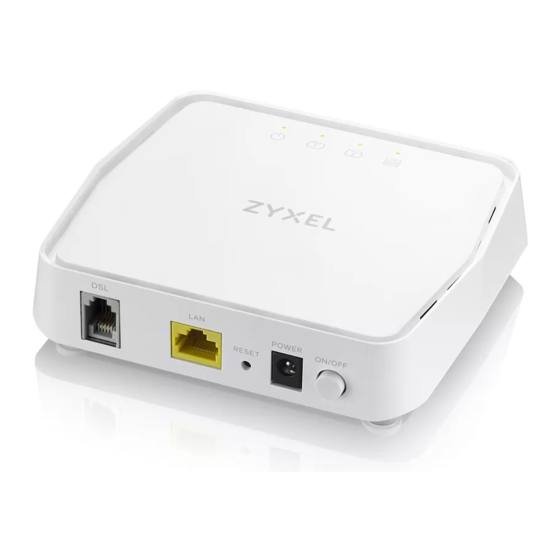
Chapter 1 Introducing the VMG 1.5 Hardware This section describes the front and rear panels for each model. Refer to the VMG’s Quick Start Guides to see the product drawings and how to make the hardware connections. 1.5.1 Front Panel The LED indicators are located on the front panel. -
Page 13: Bottom Panel
Chapter 1 Introducing the VMG Table 2 LED Descriptions (continued) COLOR STATUS DESCRIPTION Green The VMG has a successful 10/100/1000 Mbps Ethernet connection with a device on the Local Area Network (LAN). Ethernet Blinking The VMG is sending or receiving data to/from the LAN at 10/100/1000 Mbps. -
Page 14: The Web Configurator
H A P T E R The Web Configurator 2.1 Overview The Web Configurator is an HTML-based management interface that allows easy VMG setup and management via Internet browser. Use Internet Explorer 11 and later versions or Mozilla Firefox 67.0.2 and later versions or Safari 5.0 and later versions. - Page 15 Chapter 2 The Web Configurator Note: The default allowable times that you can enter the Password is 3. If you entered the wrong password for the fourth time, by default the Web Configurator will lock itself for 5 minutes before you can try entering the correct Password again. You can change these settings in Maintenance >...
-
Page 16: Web Configurator Layout
Chapter 2 The Web Configurator 2.2 Web Configurator Layout Figure 9 Screen Layout As illustrated above, the main screen is divided into these parts: • A - Menu Icon (Navigation Panel) • B - Main Window 2.2.1 Menu Icon Click this icon ( to display the navigation panel that contains configuration menus and quick links. - Page 17 Chapter 2 The Web Configurator 2.2.1.1 Quick Links The quick links provides some icons on the right hand side. The icons provide the following functions. Table 3 Quick Link Icons ICON DESCRIPTION Wizard: Click this icon to open screens where you can configure the VMG’s time zone Internet access, and wireless settings.
- Page 18 Chapter 2 The Web Configurator Note: The menu items on the navigation panel vary among the models. See Section 1.1 on page 9 for more information about the feature differences of the VMG. Table 4 Navigation Panel Summary LINK FUNCTION Connection Status Use this screen to view the network status of the VMG and computers/ devices connected to it.
-
Page 19: Chapter 3 Quick Start Wizard
H A P T E R Quick Start Wizard 3.1 Overview Use the Wizard screens to configure the VMG’s time zone and check Internet access. 3.2 Quick Start Wizard Setup You can click the Wizard icon in the navigation panel to open the Wizard screens. See Section 2.2.1.1 on page 17 for more information about the navigation panel. -
Page 20: Internet
Chapter 3 Quick Start Wizard 3.2.2 Internet The VMG will check the Internet status automatically. Click Next to proceed. You can also click Skip to pass checking of Internet connectivity in the Wizard. Figure 12 Wizard - Internet Internet Status The VMG is checking the Internet status. - Page 21 Chapter 3 Quick Start Wizard Figure 14 Wizard - Successful WAN Connection If the VMG did not detect a WAN connection, connect a DSL cable for Internet access if you have not connected any. Figure 15 Wizard - WAN Connection is Down VMG4005-B50A/B60A User’s Guide...
-
Page 22: Part Ii: Technical Reference
Technical Reference... -
Page 23: Chapter 4 Status
H A P T E R Status 4.1 Status Overview After you log into the Web Configurator, the Status screen appears. It shows the Management Service, System Info, and Ethernet UNI of the VMG. 4.2 System Info Use this screen to view the basic system information of the VMG. Figure 16 System Info Click the Arrow icon ( ) to open the following screen. - Page 24 Chapter 4 Status Figure 17 System Info: Detailed Information Each field is described in the following table. Table 5 System Info: Detailed Information LABEL DESCRIPTION Host Name This field displays the VMG system name. It is used for identification. Model Name This shows the model number of your VMG.
- Page 25 Chapter 4 Status Table 5 System Info: Detailed Information (continued) LABEL DESCRIPTION LAN Information (These fields display information about the LAN port.) IP Address This is the current IPv4 address of the VMG. Subnet Mask This is the current subnet mask. DHCP This field displays what DHCP services the VMG is providing to the LAN.
-
Page 26: Chapter 5 Log
H A P T E R 5.1 Log Overview These screens allow you to determine the categories of events that the VMG logs and then display these logs or have the VMG send them to an administrator (through email) or to a syslog server. 5.1.1 What You Can Do in this Chapter •... -
Page 27: System Log
Chapter 5 Log Table 6 Syslog Severity Levels CODE SEVERITY Informational: The syslog contains an informational message. Debug: The message is intended for debug-level purposes. 5.2 System Log Use the System Log screen to see the system logs. You can filter the entries by clicking on the Level and/ or Category drop-down list boxes. - Page 28 Chapter 5 Log Figure 19 System Monitor > Log > Security Log The following table describes the fields in this screen. Table 8 System Monitor > Log > Security Log LABEL DESCRIPTION Level Select a severity level from the drop-down list box. This filters search results according to the severity level you have selected.
-
Page 29: Chapter 6 Traffic Status
H A P T E R Traffic Status 6.1 Traffic Status Overview Use the Traffic Status screens to look at the network traffic status and statistics of the DSL and LAN interfaces. 6.1.1 What You Can Do in this Chapter •... -
Page 30: Lan Status
Chapter 6 Traffic Status The following table describes the fields in this screen. Table 9 System Monitor > Traffic Status > WAN LABEL DESCRIPTION Refresh Interval Select how often you want the VMG to update this screen. Connected This shows the name of the WAN interface that is currently connected. Interface Packets Sent Data... - Page 31 Chapter 6 Traffic Status Figure 21 System Monitor > Traffic Status > LAN The following table describes the fields in this screen. Table 10 System Monitor > Traffic Status > LAN LABEL DESCRIPTION Refresh Interval Select how often you want the VMG to update this screen. Interface This shows the LAN interface.
-
Page 32: Chapter 7 Arp Table
H A P T E R ARP Table 7.1 ARP Table Overview Address Resolution Protocol (ARP) is a protocol for mapping an Internet Protocol address (IP address) to a physical machine address, also known as a Media Access Control or MAC address, on the local area network. -
Page 33: Arp Table Settings
Chapter 7 ARP Table 7.2 ARP Table Settings Use the ARP table to view the IPv4-to-MAC address mapping(s) for the LAN. The neighbor table shows the IPv6-to-MAC address mapping(s) of each neighbor. To open this screen, click System Monitor > ARP Table. -
Page 34: Chapter 8 Mac Address Table
Chapter 8 MAC Address Table H A P T E R MAC Address Table 8.1 MAC Address Table Overview The MAC address (media access control address) of a device is a unique identifier assigned to a network interface controller for communications at the data link layer of a network segment. This table lists the MAC address of each client device. -
Page 35: Chapter 9 Xdsl Statistics
H A P T E R xDSL Statistics 9.1 xDSL Statistics Overview Use this screen to view detailed DSL information. It allows you to see the DSL status, check port details, and see DSL counters. Click System Monitor > xDSL Statistics to open the following screen. Figure 24 System Monitor >... - Page 36 Chapter 9 xDSL Statistics Table 13 System > xDSL Statistics (continued) LABEL DESCRIPTION xDSL Training This displays the current state of setting up the DSL connection. Status Mode This displays the ITU standard used for this connection. Traffic Type This displays the type of traffic the DSL port is sending and receiving. Inactive displays if the DSL port is not currently sending or receiving traffic.
- Page 37 Chapter 9 xDSL Statistics Table 13 System > xDSL Statistics (continued) LABEL DESCRIPTION This is the number of Loss Of Signal seconds. This is the number of Loss Of Frame seconds. This is the number of Loss of Margin seconds. Retr.
-
Page 38: Chapter 10 System
H A P T E R System 10.1 System Overview In the System screen, you can name your VMG (Host) and give it an associated domain name. Domain is the name given to a network. It will be required to reach a network from an external point (like the Internet). -
Page 39: Chapter 11 User Account
Chapter 11 User Account H A P T E R User Account 11.1 User Account Overview In the User Account screen, you can view and modify the settings of the “admin” and other user accounts that you use to log into the VMG to manage it. 11.2 User Account Settings Click Maintenance >... -
Page 40: User Account Add/Edit
Chapter 11 User Account Table 15 Maintenance > User Account (continued) LABEL DESCRIPTION Idle Timeout This field displays the length of inactive time before the VMG will automatically log the user out of the Web Configurator. Lock Period This field displays the length of time a user must wait before attempting to log in again after a number if consecutive wrong passwords have been entered as defined in Retry Times. - Page 41 Chapter 11 User Account The following table describes the labels in this screen. Table 16 Maintenance > User Account > Add/Edit LABEL DESCRIPTION Active Select Enable or Disable to activate or deactivate the user account. User Name Enter a new name for the account. The User Name must contain 1 to 15 characters, including 0 to 9, a to z, and !@#%*()-_+=~,.{}[]\.
-
Page 42: Chapter 12 Remote Management
H A P T E R Remote Management 12.1 Remote Management Overview Use remote management to control what services you can use through which interface(s) in order to manage the VMG. 12.1.1 What You Can Do in this Chapter • Use the MGMT Services screen to allow various approaches to access the VMG remotely from a DSL and/or LAN connection (Section 12.2 on page 42). -
Page 43: Trust Domain
Chapter 12 Remote Management The following table describes the fields in this screen. Table 17 Maintenance > Remote Management > MGMT Services LABEL DESCRIPTION WAN Interface Select Any_WAN to have the VMG automatically activate the remote management service used for services when any WAN connection is up. -
Page 44: Add Trust Domain
Chapter 12 Remote Management Figure 29 Maintenance > Remote Management > Trust Domain The following table describes the fields in this screen. Table 18 Maintenance > Remote Management > Trust Domain LABEL DESCRIPTION Add Trust Click this to add a trusted host IP address. Domain IP Address This field shows a trusted host IP address. -
Page 45: Chapter 13 Time Settings
H A P T E R Time Settings 13.1 Time Settings Overview This chapter shows you how to configure system related settings, such as system time, password, name, the domain name and the inactivity timeout interval. 13.2 Time Setup To change your VMG’s time and date, click Maintenance > Time. The screen appears as shown. Use this screen to configure the VMG’s time based on your local time zone. - Page 46 Chapter 13 Time Settings Figure 31 Maintenance > Time VMG4005-B50A/B60A User’s Guide...
- Page 47 Chapter 13 Time Settings The following table describes the fields in this screen. Table 20 Maintenance > Time LABEL DESCRIPTION Current Date/Time Current Time This field displays the time of your VMG. Each time you reload this page, the VMG synchronizes the time with the time server. Current Date This field displays the date of your VMG.
-
Page 48: Chapter 14 Log Setting
H A P T E R Log Setting 14.1 Logs Setting Overview You can configure where the VMG sends logs and which logs and/or immediate alerts the VMG records in the Logs Setting screen. 14.2 Log Setup To change your VMG’s log settings, click Maintenance > Log Setting. The screen appears as shown. If you have a LAN client on your network or a remote server that is running a syslog utility, you can also save its log files by enabling Syslog Logging, selecting Remote or Local File and Remote in the Mode field, and entering the IP address of the LAN client in the Syslog Server field. - Page 49 Chapter 14 Log Setting Figure 32 Maintenance > Log Setting The following table describes the fields in this screen. Table 21 Maintenance > Log Setting LABEL DESCRIPTION Syslog Setting Syslog Logging The VMG sends a log to an external syslog server. Click this switch to enable or disable to enable syslog logging.
- Page 50 Chapter 14 Log Setting Table 21 Maintenance > Log Setting (continued) LABEL DESCRIPTION Security Log Select the categories of security logs that you want to record. Cancel Click Cancel to restore your previously saved settings. Apply Click Apply to save your changes. VMG4005-B50A/B60A User’s Guide...
-
Page 51: Chapter 15 Firmware Upgrade
H A P T E R Firmware Upgrade 15.1 Firmware Upgrade Overview This screen lets you upload new firmware to your VMG. You can download new firmware releases from your nearest Zyxel FTP site (or www.zyxel.com) to upgrade your device’s performance. Only use firmware for your device’s specific model. - Page 52 Chapter 15 Firmware Upgrade two minutes before logging into the VMG again. Table 22 Maintenance > Firmware Upgrade LABEL DESCRIPTION Upgrade Firmware Restore Default Select the check box to have the VMG automatically reset itself after the new firmware is Settings After uploaded.
- Page 53 Chapter 15 Firmware Upgrade Figure 35 Error Message Note that the VMG automatically restarts during the upload, causing a temporary network disconnect. In some operating systems, you may see the following icon on your desktop. Network Temporarily Disconnected VMG4005-B50A/B60A User’s Guide...
-
Page 54: Chapter 16 Backup/Restore
H A P T E R Backup/Restore 16.1 Backup/Restore Overview The Backup/Restore screen allows you to backup and restore device configurations. You can also reset your device settings back to the factory default. 16.2 Backup/Restore Settings Click Maintenance > Backup/Restore. Information related to factory default settings and backup configuration are shown in this screen. - Page 55 Chapter 16 Backup/Restore back up your configuration file before making configuration changes. The backup configuration file will be useful in case you need to return to your previous settings. Click Backup to save the VMG’s current configuration to your computer. Restore Configuration Restore Configuration allows you to upload a new or previously saved configuration file from your computer to your VMG.
-
Page 56: Reboot
Chapter 16 Backup/Restore Figure 39 Reset Warning Message Figure 40 Reset In Process Message You can also press the RESET button on the bottom panel to reset the factory defaults of your VMG. Refer to Section 1.5.4 on page 13 for more information on the RESET button. - Page 57 Chapter 16 Backup/Restore Figure 41 Maintenance > Reboot VMG4005-B50A/B60A User’s Guide...
-
Page 58: Chapter 17 Diagnostic
Chapter 17 Diagnostic H A P T E R Diagnostic 17.1 Diagnostic Overview The Diagnostic screens display information to help you identify problems with the VMG. The route between a Central Office Very-high-bit-rate Digital Subscriber Line (CO VDSL) switch and one of its Customer-Premises Equipment (CPE) may go through switches owned by independent organizations. -
Page 59: Ping & Traceroute & Nslookup
Chapter 17 Diagnostic • Link trace test - provides additional connectivity fault analysis to get more information on where the fault is. If an MEP port does not respond to the source MEP, this may indicate a fault. Administrators can take further action to check and resume services from the fault according to the line connectivity status report. -
Page 60: 802.1Ag (Cfm)
Chapter 17 Diagnostic 17.4 802.1ag (CFM) Click Maintenance > Diagnostic > 802.1ag to open the following screen. Use this screen to configure and perform Connectivity Fault Management (CFM) actions as defined by the IEEE 802.1ag standard. CFM protocols include Continuity Check Protocol (CCP), Link Trace (LT), and Loopback (LB). Figure 43 Maintenance >... -
Page 61: 802.3Ah (Oam)
Chapter 17 Diagnostic Table 25 Maintenance > Diagnostic > 802.1ag (continued) LABEL DESCRIPTION MD Name Enter a descriptive name for the MD (Maintenance Domain). MA ID Enter a descriptive name to identify the Maintenance Association. MEG ID Enter a descriptive name to identify the Maintenance Entity Group. This field only appears if the Y.1731 field is enabled. -
Page 62: Oam Ping
Chapter 17 Diagnostic The following table describes the labels in this screen. Table 26 Maintenance > Diagnostics > 802.3ah LABEL DESCRIPTION IEEE 802.3ah Ethernet OAM Click this switch to enable or disable the Ethernet OAM on the specified interface. When the switch goes to the right , the function is enabled. - Page 63 Chapter 17 Diagnostic Think of a virtual path as a cable that contains a bundle of wires. The cable connects two points and wires within the cable provide individual circuits between the two points. In an ATM cell header, a VPI (Virtual Path Identifier) identifies a link formed by a virtual path;...
- Page 64 Chapter 17 Diagnostic Table 27 Maintenance > Diagnostic > OAM Ping (continued) LABEL DESCRIPTION F5 segment Press this to perform an OAM F5 segment loopback test. F5 end-end Press this to perform an OAM F5 end-to-end loopback test. VMG4005-B50A/B60A User’s Guide...
-
Page 65: Part Iii: Troubleshooting And Appendices
Troubleshooting and Appendices... -
Page 66: Chapter 18 Troubleshooting
H A P T E R Troubleshooting This chapter offers some suggestions to solve problems you might encounter. The potential problems are divided into the following categories. • Power, Hardware Connections, and LEDs • VMG Access and Login • Internet Access •... -
Page 67: Vmg Access And Login
Chapter 18 Troubleshooting 18.2 VMG Access and Login I forgot the IP address for the VMG. The default LAN IP address is 192.168.1.1. If you changed the IP address and have forgotten it, you might get the IP address of the VMG by looking up the IP address of the default gateway for your computer. -
Page 68: Internet Access
Chapter 18 Troubleshooting If the problem continues, contact the network administrator or vendor, or try one of the advanced suggestions. Advanced Suggestions • Make sure you have logged out of any earlier management sessions using the same user account even if they were through a different interface or using a different browser. •... -
Page 69: Ip Address Setup
Chapter 18 Troubleshooting Make sure you have the DSL port connected to a telephone jack (or the DSL or modem jack on a splitter if you have one). I cannot connect to the Internet using a second DSL connection. ADSL and VDSL connections cannot work at the same time. You can only use one type of DSL connection, either ADSL or VDSL connection at one time. - Page 70 Chapter 18 Troubleshooting Click Change adapter settings. Right-click the Ethernet icon, and then select Properties VMG4005-B50A/B60A User’s Guide...
- Page 71 Chapter 18 Troubleshooting Click Internet Protocol Version 4 (TCP/IPv4) and then click Properties. Select Use the following IP address and enter an IP address from 192.168.1.2 to 192.168.1.254. The Subnet mask will be entered automatically. VMG4005-B50A/B60A User’s Guide...
- Page 72 Chapter 18 Troubleshooting Click OK when you are done and close all windows. VMG4005-B50A/B60A User’s Guide...
-
Page 73: Appendix A Customer Support
• Brief description of the problem and the steps you took to solve it. Corporate Headquarters (Worldwide) Taiwan • Zyxel Communications Corporation • http://www.zyxel.com Asia China • Zyxel Communications (Shanghai) Corp. Zyxel Communications (Beijing) Corp. Zyxel Communications (Tianjin) Corp. • https://www.zyxel.com/cn/zh/ India • Zyxel Technology India Pvt Ltd • https://www.zyxel.com/in/en/ Kazakhstan •... - Page 74 • Zyxel Singapore Pte Ltd. • http://www.zyxel.com.sg Taiwan • Zyxel Communications Corporation • https://www.zyxel.com/tw/zh/ Thailand • Zyxel Thailand Co., Ltd • https://www.zyxel.com/th/th/ Vietnam • Zyxel Communications Corporation-Vietnam Office • https://www.zyxel.com/vn/vi Europe Belarus • Zyxel BY • https://www.zyxel.by Belgium • Zyxel Communications B.V. • https://www.zyxel.com/be/nl/...
- Page 75 Appendix A Customer Support • https://www.zyxel.com/be/fr/ Bulgaria • Zyxel България • https://www.zyxel.com/bg/bg/ Czech Republic • Zyxel Communications Czech s.r.o • https://www.zyxel.com/cz/cs/ Denmark • Zyxel Communications A/S • https://www.zyxel.com/dk/da/ Estonia • Zyxel Estonia • https://www.zyxel.com/ee/et/ Finland • Zyxel Communications • https://www.zyxel.com/fi/fi/ France •...
- Page 76 • Zyxel Communications Poland • https://www.zyxel.com/pl/pl/ Romania • Zyxel Romania • https://www.zyxel.com/ro/ro Russia • Zyxel Russia • https://www.zyxel.com/ru/ru/ Slovakia • Zyxel Communications Czech s.r.o. organizacna zlozka • https://www.zyxel.com/sk/sk/ Spain • Zyxel Communications ES Ltd • https://www.zyxel.com/es/es/ Sweden • Zyxel Communications • https://www.zyxel.com/se/sv/ Switzerland •...
- Page 77 Appendix A Customer Support Turkey • Zyxel Turkey A.S. • https://www.zyxel.com/tr/tr/ • Zyxel Communications UK Ltd. • https://www.zyxel.com/uk/en/ Ukraine • Zyxel Ukraine • http://www.ua.zyxel.com South America Argentina • Zyxel Communications Corporation • https://www.zyxel.com/co/es/ Brazil • Zyxel Communications Brasil Ltda. • https://www.zyxel.com/br/pt/ Colombia •...
- Page 78 Appendix A Customer Support Middle East • Zyxel Communications Corporation • https://www.zyxel.com/me/en/ North America • Zyxel Communications, Inc. - North America Headquarters • https://www.zyxel.com/us/en/ Oceania Australia • Zyxel Communications Corporation • https://www.zyxel.com/au/en/ Africa South Africa • Nology (Pty) Ltd. • https://www.zyxel.com/za/en/...
-
Page 79: Appendix B Legal Information
The contents of this publication may not be reproduced in any part or as a whole, transcribed, stored in a retrieval system, translated into any language, or transmitted in any form or by any means, electronic, mechanical, magnetic, optical, chemical, photocopying, manual, or otherwise, without the prior written permission of Zyxel Communications Corporation. Published by Zyxel Communications Corporation. All rights reserved. - Page 80 Appendix B Legal Information • If trouble is experienced with this equipment US: 1RODL01AV4005B50B (part 68 ID), for repair or warranty information, please contact Zyxel Communication Inc.; 1130 N Miller street Anaheim, CA 92806-2001, USA ;TEL: 002 +1 714-6320882. If the equipment is causing harm to the telephone network, the telephone company may request that you disconnect the equipment until the problem is resolved.
- Page 81 Appendix B Legal Information • Do not expose your device to dampness, dust or corrosive liquids. • Do not store things on the device. • Do not obstruct the device ventilation slots as insufficient airflow may harm your device. For example, do not place the device in an enclosed space such as a box or on a very soft surface such as a bed or sofa.
- Page 82 Appendix B Legal Information Symbolen innebär att enligt lokal lagstiftning ska produkten och/eller dess batteri kastas separat från hushållsavfallet. När den här produkten når slutet av sin livslängd ska du ta den till en återvinningsstation. Vid tiden för kasseringen bidrar du till en bättre miljö och mänsklig hälsa genom att göra dig av med den på...
- Page 83 North American products. Trademarks ZyNOS (Zyxel Network Operating System) and ZON (Zyxel One Network) are registered trademarks of Zyxel Communications, Inc. Other trademarks mentioned in this publication are used for identification purposes only and may be properties of their respective owners.
-
Page 84: Index
Index Index copyright customer support Address Resolution Protocol Annex A Annex B applications Internet access disclaimer ARP Table 32, 34 DSL bonding example setup DSL line backup configuration blinking LEDs bottom panel factory default reset to button RESET firmware version CCMs icon certifications... - Page 85 Index Plain Old Telephone Service, See ISDN ports product registration status language select LEDs reboot the VMG link trace registration Link Trace Message, see LTM product Link Trace Response, see LTR reset 13, 55 login RESET button passwords restart logs 26, 29, 48 restoring configuration Loop Back Response, see LBR...
- Page 86 Index time trademarks two-line splitter upgrading firmware feature difference good habits for managing managing reboot status warranty note web browser pop-up window web browser version recommended Web Configurator accessing layout login overview passwords Web pop-up blocking wireless LAN status wizard setup Internet VMG4005-B50A/B60A User’s Guide...