
Related Manuals for Planet Switch


Summary of Contents for Planet Switch
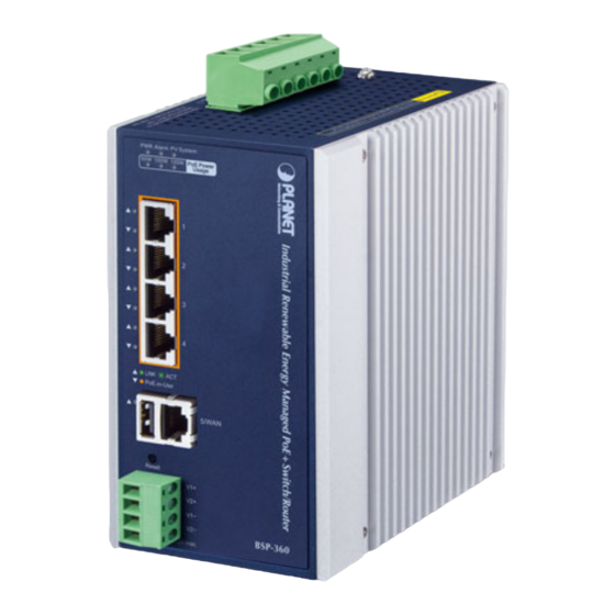
- Page 1 Industrial Renewable Power 5-Port Gigabit Managed Switch/Router with 4-Port 802.3at PoE+ BSP-360...
- Page 2 Information in this User's Manual is subject to change without notice and does not represent a commitment on the part of PLANET. PLANET assumes no responsibility for any inaccuracies that may be contained in this User's Manual. PLANET makes no commitment to update or keep current the information in this User's Manual, and reserves the right to make improvements to this User's Manual and/or to the products described in this User's Manual, at any time without notice.
- Page 3 Do not dispose of WEEE as unsorted municipal waste and have to collect such WEEE separately. Revision Industrial Renewable Energy 4-Port 10/100/1000T 802.3at PoE+ Managed Ethernet Switch User's Manual Model: BSP-360 Revision: 3.0 (MAR., 2022)
-
Page 4: Table Of Contents
2.1.2 LED Indicators ..................21 2.1.3 Upper Panel ..................22 2.1.4 Fault Alarm Connectors ................ 23 2.2 Installing the Renewable Energy Switch ............23 2.2.1 Installation Steps .................. 23 2.2.2 DIN-rail Mounting ................. 29 2.2.3 Wall Mount Plate Mounting ..............31 Management ...................... - Page 5 Industrial Renewable Energy 4-Port 10/100/1000T 802.3at PoE+ Managed Ethernet Switch/Router BSP-360 4.4 TCP/IP ......................51 4.4.1 LAN ...................... 51 4.4.1.1 LAN Setup ................... 52 4.4.1.2 Statistics ........................4.5 Battery Management ..................54 4.6 PoE Management ..................... 57 4.6.1 PoE Configuration ................58 4.6.2...
-
Page 6: Introduction
Industrial Renewable Energy 4-Port 10/100/1000T 802.3at PoE+ Managed Ethernet Switch/Router BSP-360 1. INTRODUCTION 1.1 Package Contents Open the box of the Renewable Energy Switch and carefully unpack it. The box should contain the following items: The BSP-360 x 1 ... -
Page 7: Product Description
PLANET NMS-360 Network Management Controller can centrally manage up to 512 BSP-360 units and 2,048 PLANET IP cameras via MQTT and ONVIF Protocols. (Please regularly check PLANET website for the latest compatibility list of managed devices.) - Page 8 Industrial Renewable Energy 4-Port 10/100/1000T 802.3at PoE+ Managed Ethernet Switch/Router BSP-360 Zero-Carbon and Stable Power Supply The 24V lithium or lead-acid battery gets recharged by way of the BSP-360 where solar power is sourced. Thus, the BSP-360 will keep powering PD devices without the need of any cabling. Its zero-carbon feature is made possible as the energy the unit gets is renewable.
- Page 9 For efficient management, the BSP-360 is equipped with web and SNMP management interfaces. With the built-in web-based management interface, the BSP-360 offers an easy-to-use, platform-independent management and configuration facility. By supporting the standard SNMP, the switch can be managed via any standard management software.
- Page 10 802.3at PoE+ Managed Ethernet Switch/Router BSP-360 Smart PoE PD Management including PLANET ONVIF IP Carmera As it is the managed PoE switch for surveillance, wireless and VoIP networks, the BSP-360 features the following special PoE management functions: PD alive check ...
- Page 11 Industrial Renewable Energy 4-Port 10/100/1000T 802.3at PoE+ Managed Ethernet Switch/Router BSP-360 Scheduled Power Recycling The BSP-360 allows each of the connected PoE IP cameras or PoE wireless access points to reboot at a specified time each week. Therefore, it will reduce the chance of IP camera or AP crash resulting from buffer overflow.
- Page 12 Industrial Renewable Energy 4-Port 10/100/1000T 802.3at PoE+ Managed Ethernet Switch/Router BSP-360 PoE Usage Monitoring and Intelligent LED Indicator for Real-time PoE Usage Via the power usage chart in the web management interface, the BSP-360 enables the administrator to monitor the status of the power usage of the connected PDs in real time. Thus, it greatly enhances the management efficiency of the facilities.
-
Page 13: How To Use This Manual
1.3 How to Use This Manual This User Manual is structured as follows: Section 2, Installation It explains the functions of Renewable Energy Switch and how to physically install the Renewable Energy Switch. Section 3, Management It contains information about the software function of the Renewable Energy Switch. -
Page 14: Product Features
Industrial Renewable Energy 4-Port 10/100/1000T 802.3at PoE+ Managed Ethernet Switch/Router BSP-360 1.4 Product Features Physical Port 5-port 10/100/1000BASE-T Gigabit RJ45 copper with 4-port IEEE 802.3at/af PoE injector function (Port 1 to Port 4) RJ45 type interface for basic management and setup ... - Page 15 Network Time Protocol SNMP trap for Link Up and Link Down notifications Event message logging to remote syslog server Supports PLANET ONVIF IP camera and snapshot function PLANET Smart Discovery Utility Supports PLANET NMS-360 Network Management Controller...
-
Page 16: Product Specifications
Industrial Renewable Energy 4-Port 10/100/1000T 802.3at PoE+ Managed Ethernet Switch/Router BSP-360 1.5 Product Specifications Product BSP-360 Hardware Specifications LAN: 5 10/100/1000Mbps auto MDI/MDI-X RJ45 port (Port 1 to Port 5, bridge mode) Copper Ports WAN: 1 10/100/1000Mbps auto MDI/MDI-X RJ45 port (Port 5, gateway... - Page 17 Industrial Renewable Energy 4-Port 10/100/1000T 802.3at PoE+ Managed Ethernet Switch/Router BSP-360 - Amber: 50, 100 and 120W Switching Specifications Switch Architecture Store-and-Forward Switch Fabric 10Gbps/non-blocking Switch Throughput@64 bytes 5.95Mpps@64 bytes MAC Address Table 8K entries Shared Data Buffer 512Kbit IEEE 802.3x pause frame for full duplex...
- Page 18 Low voltage cut-off protection Fully-charged hold time protection Supports PLANET ONVIF IP camera discovery PLANET ONVIF IP Camera A maximum of four PLANET ONVIF IP cameras can be powered by one Management BSP-360 switch. Supports IP camera snapshot function in the LAN.
- Page 19 Industrial Renewable Energy 4-Port 10/100/1000T 802.3at PoE+ Managed Ethernet Switch/Router BSP-360 RFC 2068 HTTP RFC 1157: SNMP v1 RFC 1902: SNMP v2c RFC 5424: Syslog Environment Temperature: -10 ~ 60 degrees C Operating Relative Humidity: 5 ~ 95% (non-condensing) Temperature: -10 ~ 70 degrees C...
-
Page 20: Installation
This section describes the hardware features of Renewable Energy Switch. For easier management and control of the Renewable Energy Switch, familiarize yourself with its display indicators and ports. Front panel illustrations in this chapter display the unit LED indicators. Before connecting any network device to the Renewable Energy Switch, read this chapter carefully. -
Page 21: Led Indicators
Industrial Renewable Energy 4-Port 10/100/1000T 802.3at PoE+ Managed Ethernet Switch/Router BSP-360 Item Interface Description Port-1~Port-4 4 10/100/1000BASE-T RJ45 auto-MDI/MDI-X ports with 802.af/at PoE+ injector function. One 10/100/1000BASE-T RJ45 auto-MDI/MDI-X port. Port-5 Port-5 functions as WAN port when the operation mode of BSP-360 is configured to “Gateway mode”... -
Page 22: Upper Panel
802.3at PoE+ Managed Ethernet Switch/Router BSP-360 2.1.3 Upper Panel The Upper Panel of the Renewable Energy Switch comes with a DC inlet power socket and one terminal block connector with 6 contacts. PV In Connector Battery In/Out The wire gauge for the terminal block should be in the range from 16 to 20 AWG. -
Page 23: Fault Alarm Connectors
Energy Switch. Please read the following sections and perform the procedures in the order being presented. To install your Renewable Energy Switch on a desktop or shelf, simply complete the following steps. In this paragraph, we will describe how to install the Renewable Energy Switch and the installation points attended to it. - Page 24 Industrial Renewable Energy 4-Port 10/100/1000T 802.3at PoE+ Managed Ethernet Switch/Router BSP-360 Please follow the following steps to install the system: Step 1. Installing BSP-360 Place the BSP-360 in a desired location using the wall-mount or DIN-rail fixtures. a. Please install the BSP-360 in a proper enclosure or shelter.
- Page 25 Industrial Renewable Energy 4-Port 10/100/1000T 802.3at PoE+ Managed Ethernet Switch/Router BSP-360 (1) Connect the negative electrode of the battery to the terminal for the negative electrode of the battery on the BSP-360. By default, the lithium battery is in use.
- Page 26 Industrial Renewable Energy 4-Port 10/100/1000T 802.3at PoE+ Managed Ethernet Switch/Router BSP-360 Step 3. Installing PV Panel (1) Connect the negative electrode of the PV panel to the terminal for the negative electrode of the PV panel on the BSP-360. (2) Connect the positive electrode of the PV panel to the terminal for the positive electrode of the PV panel on the BSP-360.
- Page 27 100 meters. If the network devices are installed outdoors, please consider to install a well-grounded lightning arrestor (such as PLANET ELA-100) to protect the network device and the BSP-360. Step 5. Wiring the DC Outputs Please follow the steps below to insert the power wires for DC power required equipment.
- Page 28 Industrial Renewable Energy 4-Port 10/100/1000T 802.3at PoE+ Managed Ethernet Switch/Router BSP-360 (3) Connect the other points of DC power wires to the power devices. Tighten the wire-clamp screws for preventing the wires from loosening. One Powered Device Two Powered Devices (4) Install the terminal block on the BSP-360.
-
Page 29: Din-Rail Mounting
2.2.2 DIN-rail Mounting This section describes how to install the Renewable Energy Switch. There are two methods to install the Renewable Energy Switch -- DIN-rail mounting and wall-mount plate mounting. Please follow the steps below. Follow all the DIN-rail installation steps as shown in the example. - Page 30 Industrial Renewable Energy 4-Port 10/100/1000T 802.3at PoE+ Managed Ethernet Switch/Router BSP-360 Step 4: Lightly remove the DIN-rail from the track.
-
Page 31: Wall Mount Plate Mounting
Step 2: Place the wall-mount plate on the rear panel of the Renewable Energy Switch. Step 3: Use the screwdriver to screw the wall mount plate on the Renewable Energy Switch. Step 4: Use the hook holes at the corners of the wall mount plate to hang the Renewable Energy Switch on the wall. -
Page 32: Management
Industrial Renewable Energy 4-Port 10/100/1000T 802.3at PoE+ Managed Ethernet Switch/Router BSP-360 3. MANAGEMENT This chapter describes how to manage the Renewable Energy Switch with the following topics included: – Overview – Requirements – Management Method 3.1 Overview The Renewable Energy Switch provides a user-friendly, Web interface where you can perform various device configuration and management activities, including: ... -
Page 33: Management Method
802.3at PoE+ Managed Ethernet Switch/Router BSP-360 3.3 Management Method User can manage the Renewable Energy Switch by Web Management via a network connection. 3.3.1 Web Management The following shows how to start up the Web Management of the BSP-360. Note the BSP-360 is configured through an Ethernet connection. - Page 34 Industrial Renewable Energy 4-Port 10/100/1000T 802.3at PoE+ Managed Ethernet Switch/Router BSP-360 Step 3. After entering the password, the main screen appears. The above banner shows the information of Green Power ,Total Power Usage, PoE Usage and Battery Capacity. Top Banner...
- Page 35 Industrial Renewable Energy 4-Port 10/100/1000T 802.3at PoE+ Managed Ethernet Switch/Router BSP-360 Step 4. The Function Menu on the left of the Web page lets you access all the functions and status the BSP-360 provides. Main Feature Banner Function Menu Now, you can use the Web management interface to continue the BSP-360 management. Please refer to the user manual for more details.
-
Page 36: Planet Smart Discovery Utility
3.3.2 PLANET Smart Discovery Utility For easily listing the Renewable Energy Switch in your Ethernet environment, Planet Smart Discovery Utility from PLANET download center is an ideal solution. The following installation instructions guide you to running Planet Smart Discovery Utility. Download Planet Smart Discovery Utility from the download center. Run this utility and the following screen appears. - Page 37 By clicking the “Control Packet Force Broadcast” function, it allows you to assign new setting value to the Ultra PoE Managed Injector Hub under a different IP subnet address. Press the “Connect to Device” button and then the Web login screen appears in Figure 3-3-2. Press the “Exit” button to shut down Planet Smart Discovery Utility.
-
Page 38: Web Configuration
BSP-360 4. WEB CONFIGURATION The Renewable Energy Switch provides Web interface for PoE smart function configuration and makes the Renewable Energy Switch operate more effectively. They can be configured through the Web browser. A network administrator can manage and monitor the Renewable Energy Switch from the local LAN. This section indicates how to configure the Renewable Energy Switch to enable its smart function. - Page 39 Description Provides System information of Renewable Energy Switch. Explained in System section 4.3 Provides WAN, LAN and network configuration of Renewable Energy Switch. TCP/IP Explained in section 4.4 Provides Battery Management configuration of Renewable Energy Switch. Battery Management Explained in section 4.5 Provides PoE Management configuration of Renewable Energy Switch.
-
Page 40: Web Panel
Industrial Renewable Energy 4-Port 10/100/1000T 802.3at PoE+ Managed Ethernet Switch/Router BSP-360 4.2 Web Panel At the top of the Web management page, the active panel displays the power status and the link status of management port and PoE ports. Figure 4-2-1: Web Panel Screen... -
Page 41: System
Industrial Renewable Energy 4-Port 10/100/1000T 802.3at PoE+ Managed Ethernet Switch/Router BSP-360 4.3 System The System function provides system information which also allows user to manage the Renewable Energy Switch system as Figure 4-3-1 is shown below: Figure 4-3-1: System Function Menu... -
Page 42: System Information
This section displays system information of Renewable Energy Switch as Figure 4-3-2 is shown below: Figure 4-3-2: System Information Menu 4.3.1.1 Status This section displays system information of Renewable Energy Switch as the screen in Figure 4-3-3 appears. Table 4-3-1 describes the system information of the Renewable Energy Switch. - Page 43 Operation Mode System Temperature Displays the current system temperature of Renewable Energy Switch. Displays the current system date of Renewable Energy Switch. The System Time system date will be correct if NTP function is enabled and the Hub is connected to Internet.
-
Page 44: Statistics
This section displays statistics information of battery capacity and PoE consumption as the screen in Figure 4-3-4 appears. Table 4-3-2 describes the system information of the Renewable Energy Switch. Figure 4-3-4: Statistics Web Page Screen Object Description Displays PoE consumption usage per hour. -
Page 45: Log
Industrial Renewable Energy 4-Port 10/100/1000T 802.3at PoE+ Managed Ethernet Switch/Router BSP-360 4.3.1.3 Log This section provides the system log setting and information display of Renewable Energy Switch as the screen in Figure 4-3-5 appears. Table 4-3-3 describes the system log setting object of Renewable Energy Switch. -
Page 46: Operation Mode
4.3.3 Time Zone This section assists you in setting the Renewable Energy Switch’s system time. You can either select to set the time and date manually or automatically obtain the GMT time from Internet as the screen in Figure 4-3-7... -
Page 47: Geolocation
Press this button to refresh the current Web page. Refresh Table 4-3-5: Descriptions of the Time Zone Configuration Objects 4.3.4 Geolocation This section provides the settings of the latitude, longitude, and altitude of Renewable Energy Switch as the screen in Figure 4-3-8 appears. Table 4-3-6 describes the Password Setting objects of Renewable Energy Switch. -
Page 48: User Management
Industrial Renewable Energy 4-Port 10/100/1000T 802.3at PoE+ Managed Ethernet Switch/Router BSP-360 4.3.5 User Management This section provides the Password Setting of Renewable Energy Switch as the screen in Figure 4-3-9 appears. Table 4-3-7 describes the Password Setting objects of Renewable Energy Switch. -
Page 49: Snmp
Industrial Renewable Energy 4-Port 10/100/1000T 802.3at PoE+ Managed Ethernet Switch/Router BSP-360 4.3.6 SNMP This section provides SNMP setting of Renewable Energy Switch as the screen in Figure 4-3-10 appears and Table 4-3-8 describes the SNMP objects of Renewable Energy Switch. -
Page 50: Remote Management
Industrial Renewable Energy 4-Port 10/100/1000T 802.3at PoE+ Managed Ethernet Switch/Router BSP-360 4.3.7 Remote Management This section provides remote management setting of Renewable Energy Switch using NMS-360 series as the screen in Figure 4-3-11 appears and Table 4-3-9 describes the SNMP objects of Renewable Energy Switch. -
Page 51: Tcp/Ip
Industrial Renewable Energy 4-Port 10/100/1000T 802.3at PoE+ Managed Ethernet Switch/Router BSP-360 4.4 TCP/IP The TCP/IP function provides WAN, LAN and network configurations of Renewable Energy Switch as Figure 4-4-1 is shown below: Figure 4-4-1: TCP/IP Function Menu The page includes the following information:... -
Page 52: Lan Setup
Figure 4-4-3 appears. Table 4-4-2 describes the LAN Objects Screen of Renewable Energy Switch. Here you may change the setting for IP address, subnet mask, DHCP, etc. Figure 4-4-3: LAN Interface Setup Web Page Screen Object Description The LAN IP address of the Renewable Energy Switch and default is IP Address 192.168.0.100. -
Page 53: Statistics
Industrial Renewable Energy 4-Port 10/100/1000T 802.3at PoE+ Managed Ethernet Switch/Router BSP-360 4.4.1.2 Statistics This page shows the packet counters for transmission and reception regarding Ethernet network as the screen in Figure 4-4-4 appears. Table 4-4-3 describes the Statistics Objects Screen of Renewable Energy Switch. -
Page 54: Battery Management
Figure 4-5-1 appears. Table 4-5-1 describes the Battery Management Objects Screen of Renewable Energy Switch. Before the configuration operation, please contact the suppliers of your battery for the product‐specific parameters. Figure 4-5-1 Battery Management Web Page Screen Object... - Page 55 Industrial Renewable Energy 4-Port 10/100/1000T 802.3at PoE+ Managed Ethernet Switch/Router BSP-360 Object Description disconnection, the controller will not supply to the load so as to protect the battery from overly discharge. DC 23.5V (23.5~27.0V) If the battery voltage is recovered and higher than the value for low Low Voltage Reconnection voltage reconnection, the low‐voltage circuit disconnection will be lifted...
- Page 56 Industrial Renewable Energy 4-Port 10/100/1000T 802.3at PoE+ Managed Ethernet Switch/Router BSP-360 Low Voltage Cut-Off Protection If the power is too low to empower the system and IP devices, the system will automatically power off the device with low priority to make sure the system works normally, and an alert is then sent to the administrator...
-
Page 57: Poe Management
Industrial Renewable Energy 4-Port 10/100/1000T 802.3at PoE+ Managed Ethernet Switch/Router BSP-360 4.6 PoE Management The PSU input power consumption is monitored by measuring voltage and current. The input power consumption is equal to the system’s aggregated power consumption. The power management concept allows all ports to be active and activates additional ports, as long as the aggregated power of the system is lower than the power level at which additional PDs cannot be connected. -
Page 58: Poe Configuration
Industrial Renewable Energy 4-Port 10/100/1000T 802.3at PoE+ Managed Ethernet Switch/Router BSP-360 4.6.1 PoE Configuration This section provides PoE (Power over Ethernet) Configuration and PoE output status of Renewable Energy Switch as screen in Figure 4-6-2 appears. Table 4-6-1 describes the PoE Configuration objects of Renewable Energy Switch. - Page 59 Industrial Renewable Energy 4-Port 10/100/1000T 802.3at PoE+ Managed Ethernet Switch/Router BSP-360 Object Description Profile1 Profile2 Profile3 Profile4 This function is available when choosing schedule on each port. Allows user to select AT/AF compatibility mode. The default value is AT Power Mode mode.
-
Page 60: Poe Status
This page allows user to see the usage of individual PoE Port as the screen in Figure 4-6-3 appears. Table 4-6-2 describes the PoE Status Objects Screen of Renewable Energy Switch. Figure 4-6-3: PoE Status Web Page Screen Object Description Port Number Displays per port status. -
Page 61: Poe Schedule
Industrial Renewable Energy 4-Port 10/100/1000T 802.3at PoE+ Managed Ethernet Switch/Router BSP-360 4.6.3 PoE Schedule This section provides user with the configurations of PoE schedule and scheduled power recycling. The “PoE schedule” helps you to enable or disable PoE power feeding for PoE ports during specified time intervals and it is a powerful function to help SMBs or enterprises save power and money. - Page 62 Industrial Renewable Energy 4-Port 10/100/1000T 802.3at PoE+ Managed Ethernet Switch/Router BSP-360 Object Description Allows user to disable or enable per port PoE function, and also allows PoE Function user to choose schedule by enabling PoE Schedule function of each port.
- Page 63 Industrial Renewable Energy 4-Port 10/100/1000T 802.3at PoE+ Managed Ethernet Switch/Router BSP-360 Object Description Set the schedule profile mode. Possible profiles are: Profile1 Profile Profile2 Profile3 Profile4 Delete Check to delete the entry. Allows user to set week day for defining PoE function by enabling it on the day.
-
Page 64: Poe Alive Check Configuration
The Renewable Energy Switch can be configured to monitor connected PD’s status in real-time via ping action. Once the PD stops working and responding, the Renewable Energy Switch are going to restart PoE port power, and bring the PD back to work. It will greatly enhance the reliability and reduces administrator management burden. - Page 65 Remote PD IP Address making ping to the PoE device. Please note that the PD’s IP address must be set to the same network segment as the Renewable Energy Switch. Interval Time (10~300s) This column allows user to set how long system should issue a ping request to PD for detecting whether PD is alive or dead.
-
Page 66: Onvif
IP surveillances. From the GUI, clients just need one click to search and show all of the ONVIF devices via network application. In addition, clients can upload floor images to the switch series, making the deployments of surveillance and other devices easy for planning and inspection purposes. -
Page 67: Onvif Device Search
Industrial Renewable Energy 4-Port 10/100/1000T 802.3at PoE+ Managed Ethernet Switch/Router BSP-360 4.7.1 ONVIF Device Search This section provides search and configuration of the ONVIF IP cam information of Renewable Energy Switch as screen in Figure 4-7-2 appears and Table 4-7-1 shows. -
Page 68: Onvif Device List
Industrial Renewable Energy 4-Port 10/100/1000T 802.3at PoE+ Managed Ethernet Switch/Router BSP-360 4.7.2 ONVIF Device List This section provides managed ONVIF IP cam information of Renewable Energy Switch as screen in Figure 4-7-3 appears and Table 4-7-2 shows. Figure 4-7-3: ONVIF IP Cam Device List Web Page Screen... -
Page 69: Preview - Snapshot
Industrial Renewable Energy 4-Port 10/100/1000T 802.3at PoE+ Managed Ethernet Switch/Router BSP-360 4.7.3 Preview – Snapshot This section provides snapshot from ONVIF IP cam of Renewable Energy Switch as screen in Figure 4-7-4 appears and Table 4-7-3 shows. Figure 4-7-3: View Snapshot Web Page Screen... -
Page 70: Maintenance
The page refreshes automatically until responses to all packets are received, or until a timeout occurs. The ICMP Ping screen in Figure 4-7-2 appears. Table 4-7-1 describes the ICMP Ping Objects Screen of Renewable Energy Switch. Figure 4-7-2: ICMP Ping Web Page Screen... -
Page 71: Usb Backup
Table 4-7-1: Descriptions of the ICMP Ping Configuration Objects Be sure the target IP address is within the same network subnet of the Renewable Energy Switch, or you have to set up the correct gateway IP address. 4.8.2 USB Backup This page shows the status of the USB HDD. -
Page 72: System Backup/Restoration
Table 4-7-3: Descriptions of the System Backup/Restoration Objects 4.8.4 Firmware Upgrade This section provides the firmware upgrade of Renewable Energy Switch as the screen in Figure 4-7-5 appears. Figure 4-7-5: Firmware Upgrade Web Page Screen... -
Page 73: Power Over Ethernet Overview
Mid-Span and End-Span. Mid-Span Mid-Span device is placed between legacy switch and the powered device. Mid-Span taps the unused wire pairs 4/5 and 7/8 to carry power; the other four are for data transmission ... - Page 74 Industrial Renewable Energy 4-Port 10/100/1000T 802.3at PoE+ Managed Ethernet Switch/Router BSP-360 Figure 5-1-1 - Power Supplied over the Spare Pins The data pairs are used. Since Ethernet pairs are transformer coupled at each end, it is possible to apply DC power to the center tap of the isolation transformer without upsetting the data transfer.
-
Page 75: The Poe Provision Process
Industrial Renewable Energy 4-Port 10/100/1000T 802.3at PoE+ Managed Ethernet Switch/Router BSP-360 6. THE POE PROVISION PROCESS While adding PoE support to networked devices is relatively painless, it should be realized that power cannot simply be transferred over existing Cat5e cables. Without proper preparation, doing so may result in damage to devices that are not designed to support provision of power over their network interfaces. -
Page 76: Classification
6.3 Start-up Once line detection and optional classification stages are completed, the PSE must switch from low voltage to its full voltage capacity (44-57 Volts) over a minimal amount of time (above 15 microseconds). -
Page 77: Power Disconnection Scenarios
Industrial Renewable Energy 4-Port 10/100/1000T 802.3at PoE+ Managed Ethernet Switch/Router BSP-360 6.5 Power Disconnection Scenarios The IEEE 802.3af / IEEE 802.3at standard requires that devices powered over Ethernet be disconnected safely (i.e. power needs to be shut down within a short period of time following disconnection of a PD from an active port). -
Page 78: Mdi Settings
Industrial Renewable Energy 4-Port 10/100/1000T 802.3at PoE+ Managed Ethernet Switch/Router BSP-360 APPENDIX A. A.1 MDI Settings The Medium-Dependent Interface (MDI or RJ45) serves as the data/power interface between Ethernet elements. As such, it has two optional connection methods to carry the power. Named Alternative A & B, Table 1 details the two power feeding alternatives. -
Page 79: Data Out Poe Injector Rj45 Port Pin Assignments
Industrial Renewable Energy 4-Port 10/100/1000T 802.3at PoE+ Managed Ethernet Switch/Router BSP-360 A.3 DATA OUT PoE Injector RJ45 Port Pin Assignments PIN NO 10BASE-T 1000BASE-T 100BASE-TX RJ45 Pin Assignment of Non-802.3af/802.3at Standard PD with PoE Mid-span PD Pin out of Cisco non-802.3af standard... -
Page 80: Recommended Use Of The Connected Wires
Industrial Renewable Energy 4-Port 10/100/1000T 802.3at PoE+ Managed Ethernet Switch/Router BSP-360 APPENDIX B. B.1 Recommended Use of the Connected Wires The wire gauges for the current are shown below: (Applicable to the system with voltage attenuation less than 3%) Gauge... -
Page 81: Bsp-360 Battery Default Setting
Industrial Renewable Energy 4-Port 10/100/1000T 802.3at PoE+ Managed Ethernet Switch/Router BSP-360 Use Lithium battery for BSP-360. You could set the Battery type at Battery Management on the web of BSP-360. B.3 BSP-360 Battery Default Setting Battery Information Type Lithium Battery...