
Related Manuals for Planet EMQ-SGS-5240 Series


Summary of Contents for Planet EMQ-SGS-5240 Series
- Page 1 L2+ Multi-Port Gigabit Stackable Managed Switch SGS-5240-24T4X/SGS-5240-24P4X SGS-5240-48T4X/SGS-5240-20S4C4XR Quick Installation Guide...
-
Page 2: Table Of Contents
Table of Contents 1. Package Contents ..................3 2. Requirements ..................... 4 3. Switch Management ..................5 4. Terminal Setup ................... 6 4.1 Logging on to the Console..............7 4.2 Configuring IP Address ................. 8 4.3 Setting 1000BASE-X for SFP+ Port ............10 4.4 Saving the Configuration ..............10 5. Starting Web Management .................11 5.1 Logging in to the Managed Switch from Management Port .....12 5.2 Saving Configuration via the Web ............13 6. Recovering Back to Default Configuration .............14... -
Page 3: Package Contents
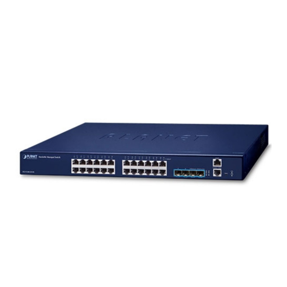
1. Package Contents Thank you for purchasing PLANET SGS-5240 L2+ Multi-Port Gigabit Stackable Managed Switch series. The descriptions of these models are as follows: Layer 2+ 24-Port 10/100/1000T + 4-Port 10G SFP+ SGS-5240-24T4X Stackable Managed Switch Layer 2+ 24-Port 10/100/1000T 802.3at PoE + 4-Port SGS-5240-24P4X 10G SFP+ Stackable Managed Switch Layer 2+ 48-Port 10/100/1000T + 4-Port 10G SFP+ SGS-5240-48T4X Stackable Managed Switch Layer 2+ 20-Port 100/1000X SFP + 4-Port Gigabit TP/ SGS-5240-20S4C4XR SFP + 4-Port 10G SFP+ Stackable Managed Switch with Redundant Power “Managed Switch” mentioned in this Quick Installation Guide refers to the above models. -
Page 4: Requirements
2. Requirements z Workstations running Windows XP/2003/Vista/7/8/2008/10, MAC OS X or later, Linux, UNIX, or other platforms are compatible with TCP/IP protocols. z Workstations are installed with Ethernet NIC (Network Interface Card) z Serial Port Connection (Terminal) The above Workstations come with COM Port (DB9) or USB-to-RS232 converter. The above Workstations have been installed with terminal emulator, such as Tera Term or PuTTY. -
Page 5: Switch Management
3. Switch Management To set up the Managed Switch, the user needs to configure the Managed Switch for network management. The Managed Switch provides two management options: Out-of-Band Management and In-Band Management. Out-of-Band Management Out-of-band management is the management through Console interface. Generally, the user will use out-of-band management for the initial switch configuration, or when in-band management is not available. -
Page 6: Terminal Setup
4. Terminal Setup To configure the system, connect a serial cable to a COM port on a PC or notebook computer and to serial (console) port of the Managed Switch. The console port of the Managed Switch is DCE already, so that you can connect the console port directly through PC without the need of Null Modem. PC / Workstation with Terminal Emulation Software Managed Switch RS232 to RJ45 Cable... -
Page 7: Logging On To The Console
4.1 Logging on to the Console Once the terminal is connected to the device, power on the Managed Switch, and the terminal will display “running testing procedures”. Then, the following message asks for the login user name and password. The factory default user name and password are as follows as the login screen in Figure 4-3 appears. -
Page 8: Configuring Ip Address
4.2 Configuring IP Address The IP address configuration commands for VLAN1 interface are listed below. Before using in-band management, the Managed Switch must be configured with an IP address by out-of-band management (i.e. console mode). The configuration commands are as follows: Switch# config terminal Switch (config)# interface vlan 1 Switch(config-if)# ip address 192.168.0.254 255.255.255.0 The previous command would apply the following settings for the Managed Switch. - Page 9 To check the current IP address or modify a new IP address for the Managed Switch, please use the procedure as follows: Show the current IP address 1. On “Switch#” prompt, enter “show ip interface vlan 1”. 2. The screen displays the current IP address, subnet mask and gateway as shown in Figure 4-5.
-
Page 10: Setting 1000Base-X For Sfp+ Port
4.3 Setting 1000BASE-X for SFP+ Port The Managed Switch supports both 1000BASE-X and 10GBASE-X SFP transceiver by manual setting and the default SFP+ port speed is set to 10Gbps. For example, to establish the fiber connection with 1000BASE-X SFP transceiver in the Ethernet 1/25, the following command configuration is required: Switch#config terminal Switch(config)#interface ethernet 1/25 Switch(config-if)#speed-duplex 1000full Figure 4-6: Setting 1000BASE-X Screen 4.4 Saving the Configuration In Managed Switch, the running configuration file stores in the RAM. In the current version, the running configuration sequence running-config can be saved from the RAM to FLASH by copy running-config startup-config command, so that the running configuration sequence becomes the start-up configuration file, which is called configuration save. -
Page 11: Starting Web Management
5. Starting Web Management The Managed Switch provides a built-in browser interface. You can manage it remotely by having a remote host with Web browser, such as Microsoft Internet Explorer, Mozilla Firefox, Google Chrome or Apple Safari. Managed Switch IP Address: MGMT 192.168.1.1 RJ45/UTP Cable PC/Workstation with Web Browser 192.168.1.x Managed Switch... -
Page 12: Logging In To The Managed Switch From Management Port
5.1 Logging in to the Managed Switch from Management Port 1. Use Internet Explorer 8.0 or above Web browser and enter IP address http://192.168.1.1 to access the Web interface. 2. When the following dialog box appears, please enter the configured username “admin” and password “admin” (or the username/password you have changed via console). The login screen in Figure 5-2 appears. Figure 5-2: Login Screen 3. After entering the password, the main screen appears as shown in Figure 5-3. -
Page 13: Saving Configuration Via The Web
4. The Switch Menu on the left of the Web page lets you access all the commands and statistics the Switch provides. Now, you can use the Web management interface to continue the Switch management or manage the Managed Switch by console interface. Please refer to the user manual for more. -
Page 14: Recovering Back To Default Configuration
6. Recovering Back to Default Configuration To reset the IP address to the default VLAN 1 interface IP address “192.168.0.100”, default Management Port IP address “192.168.1.1” or reset the login password to default value, press the hardware-based reset button on the rear panel for about 10 seconds. After the device is rebooted, you can log in the management Web interface within the same subnet of 192.168.0.xx or 192.168.1.xx. - Page 15 MGMT Console, 115200 Reset Button Reset 51/Stacking Up 52/Stacking Down Figure 6-3: SGS-5240-48T4X Reset Button...
-
Page 16: Customer Support
7. Customer Support Thank you for purchasing PLANET products. You can browse our online FAQ resource at the PLANET Web site first to check if it could solve your issue. If you need more support information, please contact PLANET support team. PLANET online FAQs: http://www.planet.com.tw/en/support/faq Support team mail address: support@planet.com.tw SGS-5240 Series User’s Manual https://www.planet.com.tw/en/support/downloads?&method=keyword&keyword=S GS-5240&view=3#list (Please select your switch model name from the drop-down menu of Product Models.)