Seagate Exos X 4006 Series Hardware Installation And Maintenance Manual
Hide thumbs
Also See for Exos X 4006 Series:
- Getting started (2 pages) ,
- Getting started (2 pages) ,
- Getting started (2 pages)
Table of Contents
Advertisement
Quick Links
Exos® X 4006 Series Hardware
Installation and Maintenance Guide
Abstract
This guide describes initial hardware setup for Seagate Exos X 4006 Series controller enclosures and disk enclosures.
It also describes removal and installation of customer-replaceable components. The guide is intended for use by
storage system administrators familiar with servers and computer networks, network administration, storage system
administration and configurations, storage area network management, and relevant protocols.
Part Number: 204380400-00
Revision: A
Published: August 2022
Advertisement
Table of Contents

Related Manuals for Seagate Exos X 4006 Series


Summary of Contents for Seagate Exos X 4006 Series
- Page 1 Installation and Maintenance Guide Abstract This guide describes initial hardware setup for Seagate Exos X 4006 Series controller enclosures and disk enclosures. It also describes removal and installation of customer-replaceable components. The guide is intended for use by storage system administrators familiar with servers and computer networks, network administration, storage system administration and configurations, storage area network management, and relevant protocols.
- Page 2 © 2022 Seagate Technology LLC or its affiliates. All rights reserved. Seagate, Seagate Technology, and the Spiral logo are registered trademarks of Seagate Technology LLC in the United States and/or other countries. Exos is a trademark of Seagate Technology LLC or one of its affiliated companies in the United States and/or other countries. All other trademarks or registered trademarks are the property of their respective owners.
-
Page 3: Table Of Contents
Contents 1 Introduction Knowledge prerequisites Product documentation and support Intended audience 2 System overview Storage enclosure components Storage enclosure chassis 2U enclosure components 5U enclosure components Controller module components Optional components 3 Initial install preparations Installation checklist Complete installation prerequisites 4 Installation of 2U enclosures Unpack and prepare the 2U enclosure Install the 2U rackmount rail kit... - Page 4 Interpret system LEDs Interpret 2U12 and 2U24 operator's panel LEDs Interpret controller module LEDs Interpret SAS 12Gb expansion module LEDs 7 Operation of 5U enclosures Apply power to the 5U enclosure Remove power from the 5U enclosure Interpret system LEDs Interpret 5U enclosure operator's panel LEDs Interpret drawer LED panels Interpret controller module LEDs...
- Page 5 Replace a 2U power cooling module 11 In-service field maintenance for 5U enclosures Replace a 5U enclosure drive module in its carrier Replace a 5U enclosure controller module Replace a 5U fan cooling module Replace a 5U power supply unit A Technical specifications B Standards and regulations International standards...
- Page 6 Figures Figure 1 2U12 and 2U24 front panel area Figure 2 2U12 and 2U24 rear panel area Figure 3 5U84 front panel area Figure 4 5U84 rear panel area Figure 5 Profile and top views of fully populated 5U84 drawers Figure 6 Controller module ports, sample SAS 4-port Figure 7 2U12 and 2U24 storage enclosure packaging Figure 8 2U enclosure outer rail components...
- Page 7 Figure 39 SAS 12Gb expansion module LEDs Figure 40 Route 5U power cords to redundant PDUs Figure 41 5U84 operator's panel LEDs Figure 42 5U84 drawer LED panel Figure 43 Controller module LEDs applicable to all variations Figure 44 Port LEDs for SAS, fibre channel, iSCSI, and 10GBase-T iSCSI controller modules Figure 45 SAS 12Gb expansion module LEDs Figure 46 USB ports on sample SAS 4-port controller module Figure 47 Sample of three switches for co-located controller enclosures, multiple host servers...
-
Page 8: Figure 28 Release Latch Open And Unlocked
Figure 79 Release latch open and unlocked Figure 80 Release latch properly locked Figure 81 Safety lock to release left drawer slide rail of lower drawer Figure 82 Controller module LEDs to examine for fault conditions Figure 83 Controller module removal, left (SAS 4-port version) Figure 84 Controller module (SAS 4-port version) Figure 85 Fan cooling module fault LEDs Figure 86 Fan cooling module removal... - Page 9 Tables Table 1 Storage enclosure variations Table 2 Installation checklist tasks Table 3 Fault LED prioritization Table 4 Fault LED prioritization Table 5 Methods of access to controller module Table 6 Interface options Table 7 Supported terminal emulator applications Table 8 Terminal emulator serial port hex codes Table 9 Sample Linux Minicom serial port parameter settings Table 10 Terminal emulator port connection settings Table 11 Factory default network port IP addresses...
-
Page 10: Introduction
Storage Bridge Bay (SBB) v2.1 compatible for interconnects, power budgets and rails, form factors, and footprints. All Seagate storage enclosures contain one or more CMs, which each contain a Hewitt Lake processor, 16GB of cache, and a custom RAID acceleration ASIC. -
Page 11: Intended Audience
Seagate storage systems Installation and use of the VSS Hardware Provider that works VSS Hardware Provider Installation Guide with Microsoft Windows Server and Seagate storage systems Compatibility information related to the product Interoperability and Compatibility Matrix Regulatory compliance, safety, and disposal information... -
Page 12: System Overview
2 System overview The Seagate Exos X storage enclosure consists of a sheet metal chassis that contains an integrated midplane and module runner system. You can mount the storage enclosure into a standard 19-inch rack cabinet, occupying either two (2U) or five (5U) EIA rack space units. -
Page 13: Storage Enclosure Chassis
1. Front panel area — Contains the operator's (ops) panel and access to drive modules in their carriers (DDICs) a. 2U enclosures — Direct access to DDICs b. 5U enclosures — Access to DDICs by opening the related drawer 2. Rear panel area — Contains controllers and methods for cooling and powering the storage enclosure Storage enclosure chassis Chassis sheet metal is bonded and riveted together and free from non-conductive coatings. -
Page 14: Figure 1 2U12 And 2U24 Front Panel Area
1 2 3 4 5 Item Description Function Input button Selects and sets UID when combined with system Locate command Drive 0 Responds to commands for drive logically numbered "0" Release latch, drive module Allows drive module insertion onto and removal from the midplane and slot Anti-tamper lock, drive module Prevents drive module removal when locked Drive 3... -
Page 15: 5U Enclosure Components
The rear panel area hosts modules designed for power, thermal cooling, and host connectivity. Item Description Function Power cooling module (PCM) Provides redundant regulation of power, temperature, and airflow PCM release latch Latches or unlatches PCM from midplane Controller module (CM) Provides data redundancy, acts as the nerve center of the storage enclosure Inverted CM Inverted PCM status LEDs... -
Page 16: Figure 3 5U84 Front Panel Area
Item Description Function Operator's (ops) panel Connects to midplane, provides users with storage enclosure information and status Drawer left sideplane indicators Registers activity for the related drive in its carrier (DDIC) and controller for the drawer's left sideplane Left pull handle in recessed Provides user access to DDICs contained in drawer pocket Drawer left side anti-tamper lock Prevents drawer access when locked... -
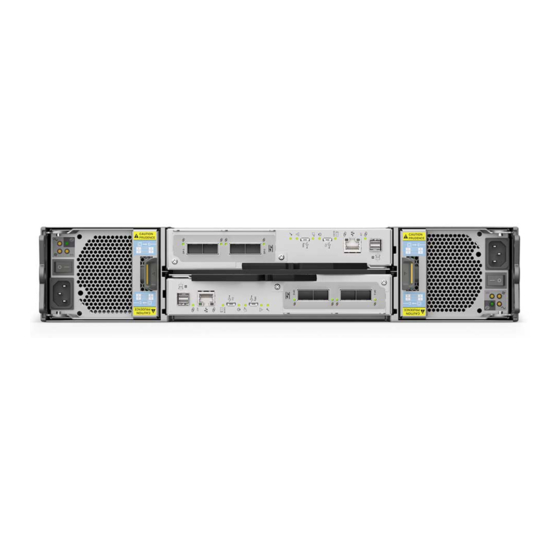
Page 17: Figure 4 5U84 Rear Panel Area
The rear panel area provides you access to modules designed for power, thermal cooling, and host connectivity. Item Description Function Controller module (CM) Provides data redundancy and is the nerve center of the storage enclosure CM release latch Provides full contact with midplane or releases controller for inspection and service CM release latch and handle Fan cooling module (FCM) Provides redundant regulation of temperature and airflow... -
Page 18: Controller Module Components
9 10 Item Description Function Drawer front with keyed anti-tamper lock and 2 Prevents or provides access to DDICs, contains dual drawer panel LEDs for drive drawer latches activity and fault status Right sideplane Registers DDIC activity and fault conditions for the primary host path Top drawer: Drawer 1 Contains slots logically numbered from 0 to 41 Operator's (ops) panel on left rack ear flange... -
Page 19: Optional Components
= SAS 4-port 12Gb/s Item Description Function SAS 12 Gb/s ports Serial Attached SCSI (SAS) 12 Gb/s data exchange with host computer Mfg USB port Manufacturing Universal Serial Bus (USB) port: do not use CLI USB port Serial command line interface port used to manage the system Ethernet port Ethernet connection to host system SAS expansion port SAS expansion 12 Gb/s data exchange with other expansion enclosures... -
Page 20: Initial Install Preparations
3 Initial install preparations Each storage enclosure installation requires the same amount of preparation to successfully mount it into your industry- standard rack cabinet of up to 1.2m in depth. WARNING! Heed all warnings and cautions on labeling and throughout this guide to reduce risk of personal injury or damage to equipment. -
Page 21: Complete Installation Prerequisites
To adhere to installation safety precautions: Site preparation 1. Use the installation checklist. 2. Clear the site for installation and secure a static-protected area. Before storage enclosure installation 1. Unpack the storage enclosure in a clear area, using appropriate safety precautions. 2. - Page 22 To complete installation prerequisites: 1. Prepare the host system for the installation by obtaining access to the following items: a. A host computer with b. A functioning switch connected to a host computer c. Tested, good cables for host connection that meet storage enclosure requirements d.
-
Page 23: Installation Of 2U Enclosures
4 Installation of 2U enclosures Sequentially follow the installation checklist to install your 2U storage enclosure. Unpack and prepare the 2U enclosure CAUTION Do not operate a storage enclosure outside the manufacturer's intended use. Storage enclosures are suitable for connection to intra-building or non-exposed wiring or cabling only. Storage enclosures are suitable for installation in locations where the National Electrical Code (NEC) applies but are not suitable for Outside Plant (OSP) installations. -
Page 24: Install The 2U Rackmount Rail Kit
5. Complete the following actions to prepare the 2U chassis for installation: a. Facing the chassis front, grasp the right rack flange cover, work the cover free, and set it aside in a safe location. b. Grasp the left rack flange cover, gently work the cover free, and set it aside in a safe location. Install the 2U rackmount rail kit The storage enclosure requires rackmount hardware for installation into a standard 1.2m rack and occupies 2 EIA units of rack space (8.89 cm or 3.50 inches) per unit. -
Page 25: Figure 8 2U Enclosure Outer Rail Components
To install the 2U rackmount rail kit: 1. Remove both outer rail assemblies from their packaging. Item Description Item Description Left front mount bracket Set screw, front Left front outer rail Set screw, rear Left rail slides Left rear mount bracket Figure 8 2U enclosure outer rail components 2. -
Page 26: Figure 9 Attachment Of Front Mount Bracket To Front Rack Cabinet Posts
Figure 9 Attachment of front mount bracket to front rack cabinet posts 6. Hold the biased mount bracket in that position and barely tighten against the front rack post using an 8mm nut driver or a Philips screwdriver. 7. Extend the length of the rail until fully mating the rear mount bracket pins in the mirror location on the rear rack post. Figure 10 Adjustment of rail length to fit rack cabinet 8. -
Page 27: Mount The 2U Enclosure Into The Rack Cabinet
Figure 11 Attachment of rear mount bracket to rear rack cabinet posts 10. Hand tighten firmly against the rack post using an 8mm nut driver or a Philips screwdriver. 11. Facing the front of the rack cabinet, hand tighten the Phillips-head M5 x 15 screw using an 8mm nut driver or a Philips screwdriver so that the hex head flange is flush with the front rack post. -
Page 28: Figure 12 Alignment Between 2U Chassis And Rails (Removed Rear Components For Clarity)
Required equipment Identification Mechanical lift Storage enclosure with attached inner rails Rack cabinet with installed outer rails #2 Phillips-head screwdriver, 6-in length Panhead screw, M5 x 8, #2 Phillips-head screw, M5 x 15, 8mm hex flange To mount the 2U enclosure into the rack cabinet: 1. -
Page 29: Figure 13 Installation Of 2U Rear Screw To Secure Chassis To Rail
4. Complete the following actions to insert the 2U chassis into the rack cabinet: a. Facing the front of the enclosure, carefully exert even pressure on both sides of the storage enclosure front, inserting the storage enclosure until the rack ear flanges are flush with the front rack posts. b. -
Page 30: Populate The 2U Enclosure
c. Hand tighten firmly against front rack post at the center of the rack ear flange. d. Slide the ops panel cover over the left rack ear flange until flush with the rack post. e. Repeat the process for the right rack ear flange and cover. Populate the 2U enclosure After successfully mounting the 2U chassis into the rack cabinet, populate the storage enclosure. -
Page 31: Route 2U Enclosure And Expansion Data Cables
IMPORTANT Use only Cat-6 or above cables with RJ-45 connectors for Base-T connections. IMPORTANT Use only Seagate approved HD mini-SAS (SFF-8644) x4 data cables that are at least .5m (1.64 ft) in length and do not exceed 3m (9.84 ft) in length to connect to the SAS ports on each controller module. -
Page 32: Figure 15 Sample Data And Management Cabling Among 2U Controllers And Host System Switches
Figure 15 Sample data and management cabling among 2U controllers and host system switches 2. Take the following actions to connect Controller 0A to its related expansion modules. The example below has 3 expansion enclosures directly below the storage enclosure. IMPORTANT Best practice is to use the expansion Port A for input and Port C for output. -
Page 33: Figure 16 Sample Reverse Cabling Method Among 2U Controller Modules (Cms) And Expansion Modules
Figure 16 Sample reverse cabling method among 2U controller modules (CMs) and expansion modules Figure 17 Sample invalid loop (in red) among 2U controller modules (CMs) and expansion modules 33 Chapter 4 Installation of 2U enclosures... -
Page 34: Route 2U Enclosure Power Cords
Route 2U enclosure power cords This basic task connects the supplied power cords to the redundant power cooling modules (PCMs) and then to independent power distribution units (PDUs) that are connected to an uninterruptible power system. You must only connect PDUs to a power source that has a safety electrical earth connection. -
Page 35: Figure 19 2U Power Cord Surrounded By Secure Tie
Figure 19 2U power cord surrounded by secure tie 6. Proceed with routing data cables in the next tasks, leaving the power on sequence until after you complete all other cabling tasks and are fully ready to test your connections. 35 ... -
Page 36: Installation Of 5U Enclosures
5 Installation of 5U enclosures Sequentially follow the installation checklist to install your 5U storage enclosure. Unpack and prepare the 5U enclosure CAUTION Do not operate a storage enclosure outside the manufacturer's intended use. Storage enclosures are suitable for connection to intra-building or non-exposed wiring or cabling only. Storage enclosures are suitable for installation in locations where the National Electrical Code (NEC) applies but are not suitable for Outside Plant (OSP) installations. -
Page 37: Install The 5U Rackmount Rail Kit
4. Locate three people to assist in moving the storage enclosure onto the mechanical lift, using an appropriate safe lifting technique to perform the following actions: a. Position one person at the front to grip the front belt strap securely by both loops, not by any portion of the front or rear panel areas. -
Page 38: Figure 21 5U Left And Right Rail Components
Required equipment Identification Outer rails, properly oriented #2 Phillips-head screwdriver, 6-in length (Optional) 8mm nut driver, 6-in length Phillips-head screw, M5 x 15, 8mm hex flange To install the 5U rackmount rail kit: 1. Remove both rail assemblies from their packaging. 2. -
Page 39: Figure 22 Insertion Of 5U Front Mount Bracket Screw
4. Select the left rail, then face the left side of the rack cabinet and slide the front mount bracket pins into the desired slots in the front rack post. 5. Insert a Phillips-head M5 x 15 screw through the rack post into the center of the front rack mount bracket and barely tighten against the front rack post, using an 8mm nut driver or a Philips screwdriver. -
Page 40: Mount The 5U Enclosure Into The Rack Cabinet
10. Facing the front of the rack cabinet, hand tighten both of the Phillips-head M5 x 15 screws using an 8mm nut driver or a Philips screwdriver so that the hex head flanges are flush with the front rack post. 11. -
Page 41: Figure 24 Alignment Between 5U Chassis And Rails, Minus Rear Components For Clarity
3. Complete the following actions to position the mechanical lift and the 5U chassis: a. Using proper safety precautions, position the 5U chassis on the mechanical lift perpendicular to the lift wheels. b. Move the mechanical lift into position perpendicular to the rack cabinet so that the storage enclosure is parallel to the opening and is a minimum of 5 to 7 inches (12.7cm to 17.78cm) away from the rack cabinet. -
Page 42: Figure 25 Secure Chassis Operator's Panel To Rack Posts
Figure 25 Secure chassis operator's panel to rack posts c. Slide the ops panel cover over the left rack ear flange until flush with the rack post. d. Repeat the process for securing the right rack ear flange and replacing the right rack ear cover. e. -
Page 43: Access A Drawer
Access a drawer Each tamper-resistant drawer contains 42 slots for drives in carriers (DDICs). The drawer supports its DDIC contents and own weight when partially or fully open. A safety latching mechanism prevents access to more than one drawer at a time. You can use a T20 Torx driver to lock each drawer pull handle by turning each lock clockwise. -
Page 44: Figure 29 Release Latch Properly Locked
c. Push the DDIC down until the top is flush with the top of the slot. d. While holding it against the bottom of the slot, slide the top latch toward the rear of the drawer until it locks into place and the DDIC ... -
Page 45: Test Enclosure Connections
IMPORTANT Use only Cat-6 or above cables with RJ-45 connectors for Base-T connections. IMPORTANT Use only Seagate approved HD mini-SAS (SFF-8644) x4 data cables that are at least .5m (1.64 ft) in length and do not exceed 3m (9.84 ft) in length to connect to the SAS ports on each controller module. -
Page 46: Figure 31 Sample Data And Management Cabling Among 5U Controllers And Host System Switches
The maximum length of any SAS cable for any configuration is 2 m (6.56-ft). All SAS cables you connect to expansion modules must be mini-SAS HD cables with SFF-8644 connectors. CAUTION Do not create invalid closed loops anywhere along the SAS port cabling configuration. A valid cabling configuration is directional and does not contain any loops between components already in that cabling configuration. -
Page 47: Figure 32 Sample Reverse Cabling Method Among 5U Controller Modules (Cms) And Expansion Modules
c. Insert a mini-SAS data cable from SAS port C in the second expansion enclosure, 2B, and connect the other end to SAS port A in the first expansion enclosure, 1B. Figure 32 Sample reverse cabling method among 5U controller modules (CMs) and expansion modules Figure 33 Sample invalid loop (in red) among 5U controller modules (CMs) and expansion modules 47 ... -
Page 48: Route 5U Enclosure Power Cords
Route 5U enclosure power cords This task provides direction to connect supplied power cords to the redundant power supply units (PSUs) connected to an uninterruptible power system. Only connect PDUs to a power source with a safety electrical earth connection. CAUTION Use only power cords supplied in the installation kit or those that meet product specifications. -
Page 49: Operation Of 2U Enclosures
6 Operation of 2U enclosures CAUTION Only operate the storage enclosure in a dust-free environment to meet temperature control and airflow requirements. Before you power on the storage enclosure, you must take the following actions: 1. Review the installation checklist, confirming the successful completion of the entire sequence. 2. -
Page 50: Remove Power From The 2U Enclosure
Figure 35 Route power cords to redundant PDUs 2. Press the power switch to the ON position for each PCM. 3. Facing the front, observe the LEDs on the front panel area and confirm the Power On LED is in a steady green state. If it is flashing amber, proceed to "Hardware installation and configuration issues"... -
Page 51: Interpret 2U12 And 2U24 Operator's Panel Leds
Table 3 Fault LED prioritization Priority Flash rate Indication Description Top priority Fast flash (1s on, 1s off) Identify Locate the enclosure or module Priority 2 Fault Fault condition detected Priority 3 Slow flash (3s on, 1s off) Logical or non-critical fault Logical fault or non-critical notification Lowest priority Off No indication System functioning normally... -
Page 52: Interpret Controller Module Leds
Interpret controller module LEDs There are two redundant controller modules (CMs) that use a series of LEDs to reflect host connectivity status. You can monitor the LEDs from the rear panel area to determine system status in combination with the user interface content. You cannot mix controller types when daisy-chaining controllers. -
Page 53: Interpret Sas 12Gb Expansion Module Leds
SAS 4-port = Fibre channel 4-port 12Gb/s = iSCSI 4-port = 10GBase-T iSCSI 4-port Protocol Description Color State Status Green Connected, link is up Green or amber Flashing Link activity 4-port 12Gb SAS link activity Amber Connected, partial link is up None Not connected or link is down Connected, link is up... -
Page 54: Figure 39 Sas 12Gb Expansion Module Leds
С Type Color State Status Ops panel undergoing 5s test Rear panel area fault: CM, fan, PSU, when paired with CM fault LED Drive module hardware fault, paired with drive module fault LED Module fault Amber Unknown, invalid, or mixed module type Flashing* Vital product data (VPD) configuration error or 1²C bus failure Rear panel area modules ... -
Page 55: Operation Of 5U Enclosures
7 Operation of 5U enclosures CAUTION Only operate the storage enclosure in a dust-free environment to meet temperature control and airflow requirements. CAUTION If you partially populate the storage enclosure with drives in their carriers (DDICs), you must comply with several additional requirements. -
Page 56: Remove Power From The 5U Enclosure
IMPORTANT Only after you successfully complete the installation checklist can you complete system setup and begin operation of the storage enclosure. To apply power to the 5U enclosure: 1. If you removed power to repair the storage enclosure, begin by facing the rear of the rack cabinet and connect the plug for each of the power to an independent power distribution unit (PDU). -
Page 57: Interpret System Leds
Interpret system LEDs Visual cues provide you with the means to monitor the storage enclosure and its components and reinforce software messages about system health. Use LEDs throughout the storage enclosure to determine if there is a critical fault. The storage enclosure registers the following states using the identified LED colors. 1. -
Page 58: Interpret Drawer Led Panels
Type Color State Status Unit identification (UID) of storage enclosure (0-99) Unit ID Green Flashing (1s on, 1s off) SCSI enclosure services (SES) controlled UID or locate active Green Storage enclosure power is on Power on or Amber Storage enclosure has AC power and is on standby as enclosure comes online standby None Storage enclosure AC power is off... -
Page 59: Interpret Controller Module Leds
LED Type Color State Status Power and Drawer power on and sideplane hardware functioning properly sideplane Green Power to drawer off Drawer module fault condition for drawer sideplane or drive Drawer module Amber Flashing (1s on, 1s off) Unit identification (UID) or locate active for drawer sideplane or drive fault Drawer modules functioning properly Drive hardware fault condition... -
Page 60: Figure 43 Controller Module Leds Applicable To All Variations
= SAS 4-port 12Gb/s Type Color State Status CM functioning properly Hardware normal Green Flashing Part of sequence as CM comes online, on standby CM power is off, CM is offline, or CM has a fault condition CM hardware fault Hardware fault Amber CM functioning properly... -
Page 61: Interpret Sas 12Gb Expansion Module Leds
SAS 4-port = Fibre channel 4-port 12Gb/s = iSCSI 4-port = 10GBase-T iSCSI 4-port Protocol Description Color State Status Green Connected, link is up Green or amber Flashing Link activity 4-port 12Gb SAS link activity Amber Connected, partial link is up None Not connected or link is down Connected, link is up... -
Page 62: Figure 45 Sas 12Gb Expansion Module Leds
С Type Color State Status Ops panel undergoing 5s test Rear panel area fault: CM, fan, PSU, when paired with CM fault LED Drive module hardware fault, paired with drive module fault LED Module fault Amber Unknown, invalid, or mixed module type Flashing* Vital product data (VPD) configuration error or 1²C bus failure Rear panel area modules ... -
Page 63: Storage Enclosure Management
8 Storage enclosure management Select a method for accessing the controller module (CM), based on your own system requirements or the requirements of your customers. Table 5 Methods of access to controller module Type Description Local serial port connection and a terminal emulator Local access to CM using serial port input and output Serial over LAN (SOL) Remote access to CM redirected serial port input and output to network... -
Page 64: Install A Device Driver
OS recognizes the USB device and can connect to a controller module. To install a device driver: 1. Navigate to https://www.seagate.com/support/systems/general-support/ and locate the device driver for download. 2. Download the zip file to the management computer. -
Page 65: Table 9 Sample Linux Minicom Serial Port Parameter Settings
An installed and tested Windows USB device driver to connect to the controller module USB port, by using the native USB serial driver for Windows 10/Server 2016 or higher, or by downloading and installing the Seagate device driver. 65 Chapter 8 Storage enclosure management... -
Page 66: Connect To A Controller Module For Configuration
To configure Windows for serial communication: 1. Start and configure the terminal emulator, using the specified settings. Table 10 Terminal emulator port connection settings Parameter Value Parameter Value Connector COM3¹ Parity None Baud rate 115,200 Stop bits Data bits Flow control None ¹... - Page 67 Table 11 Factory default network port IP addresses (continued) IP version Controller 0A addresses Controller 0B addresses Autoconfig: Enabled Autoconfig: Enabled Gateway: Gateway: IPv6 Link-Local Address: fe80::2c0:ffff:fe44:952f Link-Local Address: fe80::2c0:ffff:fe44:7010 Autoconfig IP: 6::2c0:ffff:fe44:952f Autoconfig IP: 6::2c0:ffff:fe44:7017 To connect to a controller module for configuration: 1.
-
Page 68: Storage Management Console Usage
Storage Management Console usage Seagate provides a user-friendly interface that provides the means to configure, monitor, and manage the storage system: the Storage Management Console (SMC). Access it through a supported browser, then use it to complete initial configuration of the management host, then monitor and manage the storage enclosure. -
Page 69: Access The Web-Based Management Interface
NOTE By default, your system is loaded with self-signed certificates. You should generate new self-signed certificates on each controller, using the create certificate CLI command. Expect browser warnings about security or privacy concerns related to self-signed or untrusted certificates or invalid certificate authorities. Bypass such warnings, if you are confident of a secure connection. -
Page 70: Storage Volume Replication
TIP Use the QR code on the included Getting Started sheet to access related storage enclosure documentation online. Storage volume replication Storage volume replication is a licensed feature used for disaster recovery. It requires fibre channel (FC) or iSCSI SFP connection. -
Page 71: Figure 47 Sample Of Three Switches For Co-Located Controller Enclosures, Multiple Host Servers
Sample cabling for the first controller enclosure: Two SFP I/O cables connect Controller 0A and two more connect Controller 0B to the left I/O switch. Two SFP replication cables connect Controller 0A and two more connect Controller 0B to the center replication switch. Sample cabling for the second controller enclosure: Two SFP I/O cables connect Controller 0A and two more connect Controller 0B to the right I/O switch. -
Page 72: Remote Replication Configurations
Figure 48 Sample of single switch for co-located controller enclosures, single host server Remote replication configurations Volume replication can occur on the same physical network, or on different physical networks. For situations where you need to replicate volumes in two physically remote locations, you must still isolate input and output (I/O) traffic from replication traffic. -
Page 73: Setup Storage Volume Replication
Figure 49 Sample of two remote sites, each with a controller enclosure, switch, and its own host server Setup storage volume replication After meeting all storage volume replication prerequisites and properly cabling the related primary and secondary system, use the command-line interface (CLI) the SMC to setup the replication feature. IMPORTANT Familiarize yourself with all replication-related content in the Storage Management Guide before you begin. -
Page 74: Hardware Installation And Configuration Issues
IMPORTANT Do not use this section for configured systems already interacting with production data. For the kind of assistance you need in such cases, contact Seagate for technical support. Address initial start-up issues You must successfully complete the installation tasks in the identified sequence. You must use the power cords provided with the system and install interface cables that meet system requirements. -
Page 75: Interpret Storage And Expansion Enclosure Fault Leds
6. Complete the following actions if the storage enclosure does not report as much capacity as expected: a. Verify you correctly installed the drive modules, and they are all latched to the baseplane connectors. b. Verify all installed drive module carriers display green LEDs, rather than fault LEDs. Refer to "Replace a 2U enclosure drive module in its carrier"... -
Page 76: Figure 51 2U12 And 2U24 Fault Leds On Carrier Bezel
Color State Status The drive module has a hardware fault, so replace as soon as possible The power control circuit has a hardware fault Fast flash (1s on, 1s off) Unit identification (UID) bit is set Amber Slow flash*(3s on, 1s off) Failed array Drive is functioning normally No AC power is present... -
Page 77: Figure 53 Sas 12Gb Expansion Module Fault Leds
Consult your solution service documentation for details on how to minimize system disruption during service replacement of a controller module. Fault conditions include the following: Logs or events indicate a fault condition for the CM. The Hardware fault LED on the CM is steady or flashing amber. The Hardware fault LED for the SAS expansion port on the CM is steady or flashing amber. -
Page 78: Figure 54 Power Cooling Module Fault Leds
Status Type AC fault PCM OK Fan fault DC fault Color Amber Green Amber Amber AC power not present on either PCM AC power not present on this PCM AC power present, power switch is on; PCM OK PCM fan speed is out of tolerance State PCM fan fault PCM hardware fault: over temperature, over voltage, over current... -
Page 79: 5U84 Enclosure Fault Leds
Status Type AC fault PCM OK Fan fault DC fault Color Amber Green Amber Amber AC power not present on either PCM AC power not present on this PCM AC power present, power switch is on; PCM functional PCM fan speed is out of tolerance State PCM fan fault PCM hardware fault: over temperature, over voltage, over current... -
Page 80: Figure 56 5U84 Operator's Panel Fault Leds
Type Color State Status Ops panel completing 5s test Storage enclosure rear panel area module fault: CM, fan, or PSU when paired with module fault LED Drive fault, when paired with drive fault LED Module fault Amber Unknown, invalid, or mixed module type, such as drive or PSU Flashing* VPD configuration error or 1²C bus failure Storage enclosure rear panel area modules functioning properly... -
Page 81: Figure 57 5U84 Drawer Fault Leds On Drawer Led Panel
Type Color State Status Component within drawer fault condition¹ Drive fault¹ Drawer module fault Amber Flashing* Unit ID (UID) or locate is active for drawer sideplane or drive Drawer modules functioning properly Drive hardware fault condition Logical fault Amber Flashing* One or more arrays impacted by drive hardware fault conditions Drive hardware functioning properly Cable from rear panel to drawer fault condition²... -
Page 82: Figure 59 Controller Module Fault Leds
Controller module fault LEDs The controller module (CM) has a number of ports, some with independent status LEDs. The illustration below is of the SAS four-port version of the CM. The amber LEDs listed below are the only ones that provide fault condition status. The asterisk (*) indicates a fault condition. -
Page 83: Figure 60 Sas 12Gb Expansion Module Fault Leds
С Type Color State Status Drive link is down Expansion enclosure hardware fault Unit identification (UID) or locate is active for expansion Fast flash (1s on, 1s off) module Module fault Amber Slow flash* (3s on, 1s off) Expansion module degraded or offline Expansion module functioning properly Expansion module not present Critical SAS cable fault... -
Page 84: Identify 2U Enclosure Fault Conditions
Status Type PSU fault AC fault PSU OK Color Amber Amber Green AC power not present PSU present, but not supplying power Flashing Firmware download to PSU in progress AC power present, power switch is on, providing power Flashing AC power present, PSU on standby, other PSU providing power State Communication with controller module (CM) lost PSU hardware fault... -
Page 85: Identify 5U Enclosure Fault Conditions
4. Use the command line interface (CLI). If you discover a problem, review both the SMC and the CLI for any recommended actions. 5. Visually inspect front panel area fault LEDs, then locate component fault LEDs, based on LED-identified general location. If a hardware issue prevents access to the SMC or CLI, it is the only option available. -
Page 86: Isolate Hardware And Connectivity Faults
Table 14 5U enclosure non-fault conditions Symptom Cause Recommended Action Operator's panel area LEDs, no fault conditions System power, system ID, and host connectivity LEDs System functioning properly No action required. with no module, logical, or drawer fault LEDs Drawer panel LEDs, no fault conditions Drawer power and sideplane OK LED System functioning properly No action required. -
Page 87: Isolate Replication Faults
3. Isolate the fault to one of the components in the storage enclosure. There can be a significant number of components interacting to create a viable data path, each potentially creating an issue. For example, if a host-side data error occurs, it could be hardware, such as the controller module or a faulty cable, or it could be the data host. -
Page 88: Isolate System Application Faults
b. Review event logs for notifications related to hardware faults for replication data path components and follow recommended actions. c. In the Volumes topic of the SMC, select a volume name in the volumes list, then select the Replication Sets tab, manually resume any replications that are in a suspended state. -
Page 89: Take Corrective Action For 2U Enclosures
4. For still unaddressed issues, proceed to the next section and take the recommended corrective action, based on the symptom. This may mean obtaining a replacement FRU of the same type before replacing the faulty module. Take corrective action for 2U enclosures After you follow the process above and isolate the fault to an area of the storage enclosure or to a particular module, use the following chart to determine the type of corrective action you should take. -
Page 90: Take Corrective Action For 5U Enclosures
Table 15 2U enclosure corrective action for fault conditions (continued) Symptom Cause Recommended action Thermal monitoring and control Module fault LED is on Internal temperature 1. Confirm you have met ambient temperature requirements identified in the exceeds the present Environmental Requirements section and that the air flow moves from the threshold for the storage front to the rear of the storage enclosure. - Page 91 Table 16 5U enclosure corrective action for fault conditions (continued) Symptom Cause Recommended action Module fault LED is on A fault condition related 1. Inspect the drawer panel for a fault amber LED that is on. to the hardware or system 2.
- Page 92 4. If the PSU is still failing, remove it, wait 1 minute, then reseat it. 5. If the PSU is still failing, replace it within the specified 6 minutes. 6. If the power fault condition persists, contact Seagate for support. Chapter 9 Hardware installation and configuration issues...
- Page 93 Table 16 5U enclosure corrective action for fault conditions (continued) Symptom Cause Recommended action Module fault LED is on A fault condition related 1. Restart the expansion module with a CLI or WBI command.. to the hardware in the 2. Confirm the redundant expansion module is properly functioning. rear panel area 3.
-
Page 94: 10 In-Service Field Maintenance For 2U Enclosures
10 In-service field maintenance for 2U enclosures You may service the identified storage enclosure FRUs and still maintain continuous operation during the replacement, but with two very important qualifiers: You must determine whether your system allows for continuous operation during service replacement of the storage enclosure drive modules in their carriers (DDICs) without interrupting access to enclosure file systems. -
Page 95: Replace A 2U Enclosure Drive Module In Its Carrier
g. When removing a FRU, immediately place it in anti-static packaging. h. Avoid touching pins, leads, or circuitry. Replace a 2U enclosure drive module in its carrier The operator's (ops) panel registers either a logical fault or a hardware fault or both. The drive module in its carrier (DDIC) uses an amber LED to identify various states and fault conditions. -
Page 96: Figure 64 Removal Of 2U12 And 2U24 Drive In Carrier
To replace a 2U enclosure drive module in its carrier: 1. Complete the following actions to remove a faulty DDIC: a. Facing the front of the storage enclosure, locate the DDIC with a fault condition. b. Using a thumb and forefinger, squeeze the carrier release latch to release the connection to the midplane. c. -
Page 97: Replace A 2U Enclosure Controller Module
a. Using a thumb and forefinger, squeeze the carrier release latch to release the carrier handle. Figure 65 Open 2U12 and 2U24 carrier handle b. Use one hand to support the weight of the DDIC and the other to holding it against the bottom of the slot. c. -
Page 98: Figure 66 Controller Module Leds To Examine For Fault Conditions (Sas 4-Port Version)
= SAS 4-port 12Gb/s Type Color State Status Critical SAS cable fault Fast flash* (1s on, 1s off) SAS Unit identification (UID) active SAS expansion port Amber Slow flash* (3s on, 1s off) Non-critical SAS cable fault SAS expansion port functioning properly CM hardware fault Hardware fault Amber... -
Page 99: Replace A 2U Power Cooling Module
a. Examine the tested good CM to make sure it is undamaged with pins that are straight, not bent. Figure 68 Controller module (SAS 4-port version) b. Facing the rear of the storage enclosure, orient the CM with the open latch identically to the one you just removed. c. -
Page 100: Figure 69 Power Cooling Module Fault Leds
Status Type AC fault PCM OK Fan fault DC fault Color Amber Green Amber Amber AC power not present on either PCM AC power not present on this PCM AC power present, power switch is on; PCM OK PCM fan speed is out of tolerance State PCM fan fault PCM hardware fault: over temperature, over voltage, over current... - Page 101 Status Type AC fault PCM OK Fan fault DC fault Color Amber Green Amber Amber AC power not present on either PCM AC power not present on this PCM AC power present, power switch is on; PCM functional PCM fan speed is out of tolerance State PCM fan fault PCM hardware fault: over temperature, over voltage, over current...
-
Page 102: Figure 70 Power Cooling Module Removal
To replace a power cooling module: 1. Retrieve the new PCM in its static-protected container, ready to immediately replace the faulty one. 2. Complete the following actions to remove the faulty PCM: a. Facing the rear of the rack cabinet, switch off the power for that PCM. b. -
Page 103: 11 In-Service Field Maintenance For 5U Enclosures
11 In-service field maintenance for 5U enclosures You may service the identified storage enclosure FRUs and still maintain continuous operation during the replacement, but with two very important qualifiers: You must determine whether your system allows for continuous operation during service replacement of the storage enclosure drive modules in their carriers (DDICs) without interrupting access to enclosure file systems. -
Page 104: Replace A 5U Enclosure Drive Module In Its Carrier
f. Use conductive field service tools. g. When removing a FRU, immediately place it in anti-static packaging. h. Avoid touching pins, leads, or circuitry. Replace a 5U enclosure drive module in its carrier The operator's (ops) panel registers either a logical fault or a drawer hardware fault or both. You must locate a faulty drive in its carrier (DDIC) within the related drawer by its amber fault condition LED. -
Page 105: Figure 73 Operator's Panel
Figure 73 Operator's panel Figure 74 Drawer panel b. If the anti-tamper lock is engaged, use a T20 Torx driver to unlock both drawer pull handles. c. Simultaneously press both drawer latches inward and hold them there while exerting even outward pressure until all three rows are visible and the drawer slide latch locks in the open position. -
Page 106: Figure 76 Carrier Latch Features
a. Locate the DDIC with a fault condition. Item Description Item Description Top portion of carrier latch Bottom portion of carrier latch Release latch, release latch arrow, open state 4 Fault condition LED Figure 76 Carrier latch features b. Using a thumb, press the DDIC release latch arrow to the right to release the DDIC from its seated position. c. -
Page 107: Figure 78 Replacement Of Drive In Its Carrier
Figure 78 Replacement of drive in its carrier c. Push the DDIC down until the top is flush with the top of the slot. d. While holding it against the bottom of the slot, slide the top latch toward the rear of the drawer until it locks into place and the DDIC ... -
Page 108: Replace A 5U Enclosure Controller Module
4. Complete the following actions to close the related drawer: a. Press and hold the safety lock latches with the blue touchpoint at the front of both extended drawer slide rails. Figure 81 Safety lock to release left drawer slide rail of lower drawer b. - Page 109 The CM has a number of ports, each with independent status LEDs. Those items in the state column with an asterisk (*) indicate a fault condition. Type Color State Status Critical SAS cable fault Fast flash* (1s on, 1s off) SAS Unit identification (UID) active SAS expansion port Amber Slow flash* (3s on, 1s off) Non-critical SAS cable fault SAS expansion port functioning properly...
- Page 110 Figure 83 Controller module removal, left (SAS 4-port version) c. Pull the handle outward to lever the CM away from the midplane. d. Use one hand to support the weight of the CM and the other to gently withdraw the CM from its slot. e.
-
Page 111: Replace A 5U Fan Cooling Module
4. Verify that the Hardware normal LED is lit green on the replaced CM after properly inserting and seating it in the empty slot. 5. Facing the front of the storage enclosure, verify that the Power On LED is green and there are no fault conditions. Replace a 5U fan cooling module The 5 fan cooling modules (FCMs) provide cooling to storage enclosure modules and components. -
Page 112: Replace A 5U Power Supply Unit
a. Facing the rear of the rack cabinet, press downward to release the FCM latch. b. Use one hand to support the FCM's weight and the other to gently withdraw the FCM all the way from its slot. Figure 86 Fan cooling module removal c. - Page 113 Status Type PSU fault AC fault PSU OK Color Amber Amber Green AC power not present PSU present, but not supplying power Flashing Firmware download to PSU in progress AC power present, power switch is on, providing power Flashing AC power present, PSU on standby, other PSU providing power State Communication with AP controller module (CM) lost PSU hardware fault...
- Page 114 2. Complete the following actions to remove the faulty PSU: a. Facing the rear of the rack cabinet, switch off the power for that PCU, then disconnect its power cord. b. Press the PSU release latch to the right to release the PSU from the midplane. c.
-
Page 115: A Technical Specifications
A Technical specifications Table 19 Storage enclosure dimensions Dimension type 2U12, 2U24 5U84 Metric units Imperial units Metric units Imperial units Height 87.90mm 3.46 in 220.00mm 8.65 in Width, excluding rails 483.00mm 19.01 in 483.00mm 19.00 in Depth, excluding cables 630.00mm 24.80 in 933.00mm... -
Page 116: Table 22 Power Specifications
Table 22 Power specifications Type Description Input power 100VAC to 240VAC, 50Hz to 60Hz 200VAC to 240VAC, 50Hz to 60Hz requirements Voltage Max output: 764W or 580W Max output: 2200W Range: 100-240VAC, rated Range: 200-240VAC, rated Frequency: 50-60Hz Frequency: 50-60Hz Hot- HDDs and SSDs (in chassis data slots), controller HDDs and SSDs (in chassis data slots), controller modules (CMs),... -
Page 117: B Standards And Regulations
B Standards and regulations International standards The storage enclosure complies with the requirements of the following agencies and latest editions of these standards: Table 23 Standard and approvals Type Specification UL 60950-1; UL & cUL to UL 62368-1 2nd Ed CAN/CSA-C22.2 No. -
Page 118: Index
Index 2U12 failure, hardware 86, large form factor (LFF) enclosure 12-13, 94, 103, cable, connector, or switch 87, 91-92 drive module 2U24 small form factor (SFF) enclosure 12-13, 94, 103, fan modules 15, 99, fault condition 84-85, 89-90 fault isolation cabling firmware update 78, cable management system... - Page 119 safety guidelines 24, replacement, in-service FRU controller module 97, drive module or DDIC 95, fan cooling module (FCM) power cooling module (PCM) power supply unit (PSU) time limits 94, return FRU for repair 95, 97, 104, packaging 23, storage enclosure 23, safety precautions electrical 30, equipment disposal...