
Related Manuals for Iwatsu SS-500 Series


Summary of Contents for Iwatsu SS-500 Series
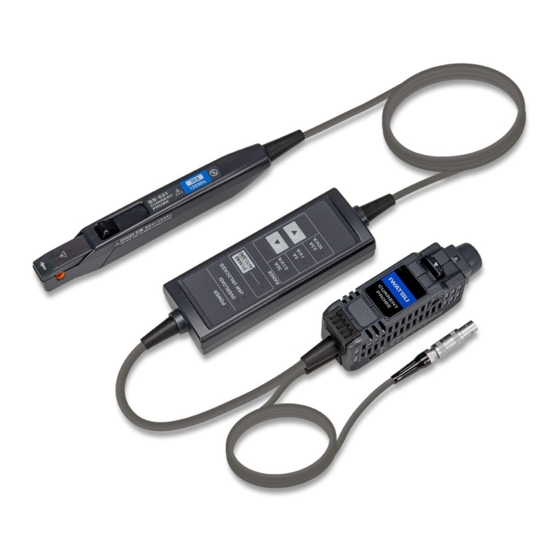
- Page 1 Instruction Manual Current Probe SS-530 / SS-531 Distributed by: Sie haben Fragen oder wünschen eine Beratung? Angebotsanfrage unter +49 7121 / 51 50 50 oder über info@datatec.eu...
- Page 2 Ⓒ2021 IWATSU ELECTRIC CO., LTD. All rights reserved....
- Page 3 Measurement Procedure Be sure to familiarize yourself with the “Usage Notes” section (p. 8 ), each instruction of use, and safety notes presented at the beginning of each instruction of use. (p. 2 6) Inspecting the Device Before Use (p. 2 8) Preparing for Measurement •...
- Page 4 Connection Example Waveform measuring instrument Power source Load Model PS-54 Power Supply See “Example of connection to the circuit to be measured” (p. 4 9).
-
Page 5: Table Of Contents
CONTENTS Introduction ................1 Notations ..................2 Checking Package Contents ............. 5 Safety Notes ................7 Usage Notes ................8 Overview ................13 1.1 Product Overview ..............13 1.2 Product Features ............... 14 1.3 Name and Function of Each Part ..........16 Termination unit ................ - Page 6 Specifications ..............69 3.1 General Specifications .............. 69 3.2 Specifications of Input, Output and Mesurement ....71 Basic specifications ..............71 Specifications of accuracy ............73 3.3 Specifications of Functionality ..........75 3.4 Typical Characteristics ............. 77 Frequency characteristics ............77 Frequency derating curve ............
-
Page 7: Introduction
Introduction Introduction Thank you for choosing the IWATSU SS-530, SS-530 Current Probe. To ensure your ability to get the most out of this device over the long term, please read this manual carefully and keep it available for future reference. -
Page 8: Notations
Notations Notations Safety notations This manual classifies seriousness of risks and hazard levels as described below. Indicates an imminently hazardous situation DANGER that, if not avoided, will result in death or serious injury. Indicates a potentially hazardous situation WARNING that, if not avoided, could result in death or serious injury. - Page 9 Notations Indicates an action that must not be performed. Indicates an action that must be performed. Symbols shown on the device Indicates the presence of a potential hazard. For more information about locations where this symbol appears on device components, see the “Usage Notes” section (p. ...
- Page 10 Indicates additional information is described below. Bold Indicates the names of the control keys. Accuracy IWATSU defines tolerances for measured values in terms of percentage of reading, as indicated below. Reading (Displayed value) Indicates the value the measuring instrument rdg.
-
Page 11: Checking Package Contents
If you find any damage or discover that the device does not perform as indicated in its specifications, please contact your authorized IWATSU distributor or reseller. Check that the package contents are correct. Model SS-530/SS-531 Current Probe ······· 1 ... - Page 12 The option below is available for the device. To order an option, please contact your authorized IWATSU distributor or reseller. Options are subject to change. Check IWATSU’s website for the latest information. Model PS-54 Power Supply The PS-54 Power Supply can provide the power to up to two probes of the SS-530/SS-531.
-
Page 13: Safety Notes
Safety Notes Safety Notes The device has been designed in accordance with the IEC 61010 safety standard, and its safety has been verified by means of testing prior to shipment. However, failure to follow the information in this manual could render safety-related functionality provided by the device ineffective. -
Page 14: Usage Notes
Usage Notes Usage Notes Be sure to follow the precautions listed below in order to use the device safely and in a manner that allows it to function effectively. Use of the device should conform not only to its specifications, but also to the specifications of all accessories, options, and other equipment in use. - Page 15 Usage Notes DANGER Do not remove any covers of the sensor, junction box, and termination unit. The internal components of the device carry high voltages and may become very hot during operation. Touching them could cause electric shock or burns. ...
- Page 16 Usage Notes WARNING Do not use the device to measure circuits that exceed the ratings or specifications of the device. Doing so could cause damage to the device or overheating, resulting in bodily injury. Do not install the instrument in locations such as the following: •...
- Page 17 Iwatsu office or our sales distributors for inside cleaning together with periodical inspection and calibration once a year or so.
- Page 18 Usage Notes NOTICE Do not store or use the device in locations subject to abrupt temperature changes. Doing so could damage the sensor heads. Do not apply force in the directions shown in the figure below while the upper jaw is locked in place.
-
Page 19: Overview
Overview 1.1 Product Overview Model SS-530/SS-531 is a clamp-on current probe that features high current-detection sensitivity and broad frequency band. The probe uses three current ranges to detect current waveforms from 1 mA to 50 A. You can directly connect the termination unit to a BNC input terminal of your waveform measuring instrument such as an oscilloscope and recorder, and then clamp the sensor around a conductor to be measured to observe current... -
Page 20: Product Features
Product Features 1.2 Product Features Clamp-on sensor heads (p. 2 1) The clamp-on sensor heads allow current measurement without the need to make physical contact with a conductor to be measured or to disconnect it. You can observe current waveforms while maintaining the flow of electric current. - Page 21 Product Features Three current measurement ranges (p. 5 3) You can choose from the three ranges according to the magnitude of the current to be measured. This feature lets you observe a wide range of currents, from 1 mA to 50 A. Broad frequency band (p. ...
-
Page 22: Name And Function Of Each Part
Name and Function of Each Part 1.3 Name and Function of Each Part Termination unit See p. 3 4 and p. 3 5. Top view... - Page 23 Name and Function of Each Part Output terminal The device converts a captured current waveform into a voltage waveform by multiplying a particular sensitivity according to a specified current range and outputs the voltage waveform from this terminal. Connect this terminal to a BNC input terminal of your waveform measuring instrument.
-
Page 24: Junction Box (Keys, Leds)
Name and Function of Each Part Junction box (keys, LEDs) Top view DEMAG / AUTO ZERO Hold down Performs demagnetization followed by automatic zero-adjustment. (p. 3 3) (about 1 s) Press momentarily Performs automatic zero-adjustment alone. (p. 4 0) (less than 0.5 s) ... - Page 25 Name and Function of Each Part POWER LED (green light) • Lights up when the power is on (p. 3 1). (Normal operation) • Rapidly blinks when a checksum error has occurred (p. 9 5). OVERLOAD LED (red light) • Flashes three times when demagnetizing or automatic zero- adjustment cannot be performed (p. ...
-
Page 26: Sensor
Name and Function of Each Part Sensor NOTICE Do not store or use the device in locations subject to abrupt temperature changes. Do not apply force or mechanical shock to the device. Do not subject the device to static electricity. Doing so could damage the device. - Page 27 Name and Function of Each Part Jaws Clamp this part around a conductor to be measured by operating the opening lever, which allows the upper jaw to slide (retract/extend). Sensor aperture A conductor to be measured must pass through this aperture.
-
Page 28: Specifications Of Lighting Up / Blinking Leds
Specifications of Lighting Up / Blinking LEDs 1.4 Specifications of Lighting Up / Blinking LEDs : Lighting up : Off : Blinking Device state Green Automatic zero- Overload Others POWER adjustment − − (On start-up) 2 Not performed Not detected (Initial state) In execution −... - Page 29 Specifications of Lighting Up / Blinking LEDs Orange Green DEMAG / AUTO RANGE OVERLOAD JAW UNLOCKED ZERO 30 A 0.5 A Slowly* Specified range only Specified range only ...
- Page 30 Specifications of Lighting Up / Blinking LEDs...
-
Page 31: Current Measurement
Current Measurement WARNING Do not clog the vents on the sides and bottom of the termination unit (p.16). Doing so could cause internal overheating of the termination unit, resulting in bodily injury, fire, or damage to the device. Do not pile the junction box (p.18) on another. -
Page 32: Inspecting The Device Before Use
• Model PS-54 Power Supply (available as an option) • Waveform measuring instrument (such as oscilloscope and recorder) Connecting the SS-530/SS-531 to a IWATSU Oscilloscope option with a power supply module for current probes (option) installed allows the SS-530/SS-531 to operate without the PS-54 Power Supply. - Page 33 Inspecting the Device Before Use Inspecting appearance and functionality of the device and condition of conductors to be measured Have the device repaired. Are the sensor, junction box, and termination Damage can cause unit damaged? electric shock. Have the device repaired. Is the insulation of each Damage can cause cord damaged?
-
Page 34: Preparing For Measurement
Preparing for Measurement 2.2 Preparing for Measurement WARNING Turn off all equipment before connecting the device. Failure to do so can cause electric shock or a short- circuit. CAUTION Before connecting the power cord to the inlet on the rear panel of the PS-54 Power Supply, verify that the supply voltage you plan to use falls within the supply voltage range noted on the PS-54. -
Page 35: Providing Power To The Ss-530/Ss-531
Preparing for Measurement Providing power to the SS-530/SS-531 IMPORTANT Do not allow the total consumption current of the current sensors connected with the PS-54 Power Supply to exceed the rated output current of the PS-54. The consumption current of the SS-530/SS-531 depends on current under measurement. - Page 36 Preparing for Measurement How to provide the power to the SS-530/SS-531 Ensure that the POWER switch of the PS-54 Power Supply is set to OFF. Connect the power cord to the power inlet on the back of the PS-54 Power Supply. Slide the opening lever of the sensor toward the lower jaw until the...
- Page 37 Preparing for Measurement Set the POWER switch of the PS-54 Power Supply to the ON position. The LEDs of the SS-530/SS-531 and the PS-54 will light up or blink as follows: Model PS-54 POWER indicator will light up. Model SS-530/SS-531 All LEDs will light up for 1 s, and then the SS-530/ SS-531 will operate as follows: •...
- Page 38 Preparing for Measurement Wait for 30 minutes or more. Wait at least 30 minutes after starting to supply power to the SS-530/SS-531 to accurately measure a current before executing demagnetization and automatic zero- adjustment. See “Executing demagnetization and automatic zero-adjustment” (p. 3 3). ...
-
Page 39: Executing Demagnetization And Automatic Zero-Adjustment
Preparing for Measurement Executing demagnetization and automatic zero-adjustment WARNING Do not hold down the DEMAG / AUTO ZERO key when the sensor is clamped around a conductor under measurement. Conductor under measurement Do not hold down the key. Doing so will start magnetization, causing bodily injury or damage to the circuit under measurement. - Page 40 Preparing for Measurement NOTICE Do not subject the connection to force. Do not rotate the output terminal while the termination unit is connected with a waveform measuring instrument. Doing so could damage the output terminal on the termination unit or the BNC input terminal on the waveform measuring instrument.
- Page 41 Preparing for Measurement NOTICE Arrange the termination unit and a BNC input terminal of your waveform measuring instrument in a straight line when connecting the termination unit. Failure to do so may damage the output terminal. When connecting the output terminal to an input terminal that is not a BNC terminal through a conversion plug, make sure that the polarity is as follows:...
- Page 42 Preparing for Measurement What is demagnetization? The magnetic core can be magnetized, which results from turning power on and off, inputting an excessively large current, or other factors. Executing demagnetization eliminates magnetic charges. What is automatic zero-adjustment? Automatic zero-adjustment corrects variations in the offset voltage caused by factors such as the device-specific offset voltage and variations in temperature.
- Page 43 Preparing for Measurement How to execute demagnetizing and automatic zero- adjustment IMPORTANT Do not move the sensor during demagnetization or automatic zero-adjustment. Disturbance (such as external magnetic fields and temperature changes) may prevent demagnetization or automatic zero-adjustment from being completed normally.
- Page 44 Preparing for Measurement Set the input coupling of the waveform measuring instrument to DC. Connect the output terminal of the termination unit to a BNC input terminal of the waveform measuring instrument. • Insert the output terminal straight. • Insert the output terminal until it clicks so that it is securely locked in position.
- Page 45 Preparing for Measurement Hold down the DEMAG / AUTO ZERO key on the junction box for about 1 second. Hold down DEMAG / AUTO ZERO LED will light up. Demagnetization and automatic zero-adjustment will start. Green will light up Orange will light up After the completion, the DEMAG / AUTO ZERO will go out.
- Page 46 Preparing for Measurement If the DEMAG / AUTO ZERO LED flashes three times, the device cannot perform demagnetization or automatic zero- adjustment. Implement the remedy described on the following page. “Demagnetizing / automatic zero-adjustment unavailable” (p. 9 2) To halt demagnetization or automatic zero-adjustment on the middle of its execution ...
-
Page 47: Measuring Currents
Measuring Currents 2.3 Measuring Currents Be sure to read the following sections and perform the steps described there before taking measurements: “2.1 Inspecting the Device Before Use” (p. 2 6) “2.2 Preparing for Measurement” (p. 2 8) Follow all operating precautions for your waveform measuring instrument or any other measuring instrument. - Page 48 Measuring Currents DANGER Do not subject the ground side of other input terminals to a different potential when you use one of the following waveform measuring instruments: • an instrument that does not provide electrical insulation between its input terminals and chassis •...
- Page 49 Measuring Currents DANGER Ensure that the insulation on a conductor is not worn or damaged before clamping the sensor around the conductor to be measured. Take care not to damage the insulation when clamping the sensor around the conductor. Damage to the conductor insulation can cause electric shock.
- Page 50 Measuring Currents WARNING While measuring a high-frequency current or a current that includes high-frequency components, keep hands and other body parts away from the jaws. Eddy current loss may cause heating of the sensor heads. Failure to do so could fire or damage to the measurement target and device, resulting in burns.
- Page 51 Measuring Currents CAUTION Do not place any conductor carrying a current with a frequency of 10 kHz or more close to the jaws even when the sensor is not clamped around a conductor. Do not place conductors not to be measured close to the jaws.
- Page 52 Measuring Currents CAUTION Do not prevent heat radiation from the device. Do not input a current that exceeds the maximum rated current value*. An temperature increase in the device cause burns, damage to the device, or a short-circuit. ...
- Page 53 Measuring Currents CAUTION Use the device for measuring currents much lower than the maximum rated current value if an ambient temperature is relatively high or a current to be measured can contain frequency components other than the fundamental. Self-heating could cause burns or damage to the device even if the current under measurement is lower than the maximum rated current.
- Page 54 Measuring Currents NOTICE Do not subject the sensor to high voltage, including static electricity. Doing so may damage the device. Do not pass a current through a conductor under measurement when the PS-54 Power Supply or your waveform measuring instrument is off.
- Page 55 The PS-54 Power Supply can provide the power to up to two probes of the SS-530/SS-531. Connecting the SS-530/SS-531 to a IWATSU Oscilloscope option with a power supply module for current probes (option) installed allows the SS-530/SS-531 to operate without the PS-54 Power Supply.
-
Page 56: How To Measure A Current
Measuring Currents How to measure a current IMPORTANT Do not place the sensor close to a heat source. Do not roughly operate the opening lever to lock the upper jaw. Do not subject the jaws and opening lever to force.... - Page 57 Measuring Currents Pull the opening lever of the sensor toward you to retract the upper jaw. Low-potential side Clamp the sensor around (Ground potential a conductor to be side) measured. • Have the current direction indicator match the High- direction of the current to be potential side measured.
- Page 58 Measuring Currents Check the LEDs on the junction box. POWER LED and one of the RANGE LEDs light up. There is no error. Go on to step OVERLOAD LED blinks rapidly. The device has detected a measurement current in excess of the level defined for the current range.
- Page 59 Measuring Currents Press the (higher range) key or (lower range) key to choose a current range. • Choose a current range with a maximum peak current higher than the peak value of a current under measurement. See “Maximum peak current” (p. 7 2). If the peak value of the current under measurement exceeds the maximum peak current of the chosen current range, the output waveform will be saturated or distorted,...
- Page 60 Measuring Currents Convert a voltage sensitivity of the waveform measuring instrument into a current sensitivity. Using the following formula can convert a voltage sensitivity (unit: V/div) specified on the waveform measuring instrument into a current sensitivity (unit: A/div). : Current sensitivity (A/div) : Voltage sensitivity (V/div) : Output sensitivity (V/A) Example...
- Page 61 Measuring Currents IMPORTANT After you measured a current that exceeds the maximum rated current value of each current range, re-execute the demagnetization and automatic zero- adjustment. The sensor heads have been magnetized, causing incorrect current measurements. See “Executing demagnetization and automatic zero- adjustment”...
- Page 62 Measuring Currents IMPORTANT When you measure high-frequency currents, Clamping the sensor around the high-potential side of a circuit may cause common-mode noise to affect the measurement accuracy adversely. See “Influence of common-mode voltage” (p. 8 2). As needed, reduce the frequency band of the waveform measuring instrument, or clamp the sensor around the low- potential side conductor.
- Page 63 Measuring Currents NOTE • Depending on the amplitude and frequency of a current under measurement, the sensor heads may emit a resonant sound. Such a sound may also be emitted during demagnetization. This, however, does not represent a device malfunction. •...
-
Page 64: To Measure A Low Current
Measuring Currents To measure a low current When measuring low DC or low-frequency low AC, you can increase the current-detection sensitivity of the device in the following way. How to measure a low current Coil a single conductor to be measured into several loops with a diameter of 200 mm or more. - Page 65 Measuring Currents As shown in the figure below, clamping the sensor around the seven loops in a bundle allows the conductor to pass through the sensor aperture eight times, which increases the voltage of the output signal by a factor of eight. ...
-
Page 66: To Measure A Current Accurately
Measuring Currents To measure a current accurately Retracting and extending the upper jaw can cause an offset voltage of several millivolts. Perform the steps described below before measuring a current to measure it accurately. How to measure a current accurately Hold down the DEMAG / AUTO ZERO... - Page 67 Measuring Currents Slide the opening lever toward the lower jaw until JAW UNLOCKED indicator is hidden. The upper jaw will be locked with the upper and lower sensor heads arranged in position relative to each other. JAW UNLOCKED LED will go out.
-
Page 68: When The Device Has Entered Protection Mode
Measuring Currents When the device has entered protection mode To protect the device against self-generated heat, it enters protection mode when the temperature of the junction box exceeds a specified level. Green lights up Reds blink rapidly Orange blinks rapidly Greens blink rapidly In protection mode, the device cannot correctly measure any current. - Page 69 Measuring Currents How to restore the device Pull the opening lever of the sensor toward you to retract the upper jaw, and remove the sensor from the conductor under measurement. Slide the opening lever toward the lower jaw until the UNLOCKED indicator is hidden.
- Page 70 Measuring Currents Press any key. One of the RANGE LEDs (of the range used before the device entered protection mode) will light up, and the device will get back to normal. Press any DEMAG / AUTO ZERO LED will blink slowly. Perform demagnetization and automatic zero- adjustment.
-
Page 71: Finishing Measurement
Finishing Measurement 2.4 Finishing Measurement NOTICE Do not pull the cord to unplug the output terminal. Doing so can damage the cord and output terminal. Hold the termination unit and disconnect the output terminal while pulling the unlock lever toward you. - Page 72 Finishing Measurement NOTICE To disconnect the power plug of the device, do not pull the cord. Do not twist the power plug. Doing so could damage the cord and the power receptacle of the PS-54 Power Supply. While holding the shell (p.17), pull the power plug out.
- Page 73 Finishing Measurement How to finish measurement Pull the opening lever of the sensor toward you to retract the upper jaw, and remove the sensor from the conductor under measurement. Slide the opening lever toward the lower jaw until JAW UNLOCKED indicator is hidden.
- Page 74 Finishing Measurement Disconnect the power plug of the SS-530/SS-531 from the PS-54 Power Supply. Hold the shell (p. 1 7) of the power plug when you disconnect it. Do not pull the cord. Do not twist the power plug. Unplug the power cord of the PS-54 Power Supply from the outlet.
-
Page 75: Specifications
Specifications Unless otherwise specified, each specification item is applied to both Model SS-530 and Model SS-531. Items with a model number, “(Model SS-530)” or “(Model SS-531),” indicated are applicable to each model. Each item is specified for the device operated at 23°C±5°C (73°F±9°F) and 80% RH (no condensation), 30 minutes elapses after the device is turned on before use. - Page 76 General Specifications Power supply External power supply (Model PS-54) Rated supply voltage: ±12 V DC ±0.5 V Maximum rated power: 7.8 VA (For current probe only, when measuring 30 A rms continuously) Consumption current See “Consumption current” (p. 8 1) in “3.4 Typical Characteristics.”...
-
Page 77: Specifications Of Input, Output And Mesurement
Specifications of Input, Output, and Measurement 3.2 Specifications of Input, Output and Mesurement Basic specifications Frequency band DC to 50 MHz (−3 dB) (Model SS-530) DC to 120 MHz (−3 dB) (Model SS-531) See “Frequency characteristics” (p. 7 7) in “3.4 Typical Characteristics.”... - Page 78 Specifications of Input, Output, and Measurement Maximum rated current* 30 A range: 30 A rms 5 A range: 5 A rms 0.5 A range: 0.5 A rms Derating is needed as input frequency increases. See “Frequency derating curve” (p. 7 8) in “3.4 Typical characteristics.”...
-
Page 79: Specifications Of Accuracy
• Accuracy warranty period 1 year (until the upper jaw has been retracted and locked up to 10,000 cycles) • Guaranteed accuracy period after adjustment made by IWATSU 1 year • Temperature and humidity for guaranteed accuracy 23°C±5°C (73°F±9°F), 80% RH or less •... - Page 80 Specifications of Input, Output, and Measurement Temperature characteristics of sensitivity* ±2.0% rdg. or less After automatic zero-adjustment was executed, in the temperature range except 23°C±5°C, under the following input conditions: 30 A range: AC with 50 Hz, 30 A 5 A range: AC with 50 Hz, 5 A 0.5 A range: AC with 50 Hz, 0.5 A Effect of radiated radio-frequency electro-magnetic field ±10 mA or less at 3 V/m...
-
Page 81: Specifications Of Functionality
Specifications of Functionality 3.3 Specifications of Functionality Demagnetizing and automatic zero-adjustment functions When the upper jaw is not locked in place, an overload is detected, or an inputted current exceeds the values listed below, the functions are not available. 0.50 ±0.25 A rms (DC and sine wave with frequencies of 45 Hz to 66 Hz) •... - Page 82 Specifications of Functionality Overload detection • Typical sampling frequency: 7.8125 kHz • Typical checking cycle: 500 ms Breakdown Typical sampling period: 400 ms Typical computing-and-judging period: 100 ms (1) Excess of rated current level When the input current exceeds the following level, the OVERLOAD LED blinks rapidly.
-
Page 83: Typical Characteristics
Typical Characteristics 3.4 Typical Characteristics All of the characteristics shown in this section are typical. Frequency characteristics 0.5 A range (10 V/A) 5 A range (1 V/A) −10 30 A range (0.1 V/A) −20 −30 −40 100k 10M 100M Frequency [Hz] Fig. -
Page 84: Frequency Derating Curve
Typical Characteristics Frequency derating curve Figures 3 and 4 show the derating curves with a sine-wave current inputted in the temperature and humidity range for the guaranteed accuracy. If the ambient temperature (T rises or the current under measurement contains high- frequency components, the device temperature will rise, and thus its continuously inputtable current value and frequency will lower. - Page 85 Typical Characteristics 100k 100M Frequency [Hz] Fig. 3 Derating curve according to frequency (Model SS-530) 100k 100M Frequency [Hz] Fig. 4 Derating curve according to frequency (Model SS-531)
-
Page 86: Input Impedance
Typical Characteristics Input impedance The location where the sensor is clamped will exhibit impedance as shown in Figs. 5 and 6, which inserts a load in a circuit under measurement. In particular, take this characteristic into account when measuring a high-frequency current. -
Page 87: Consumption Current
Typical Characteristics Consumption current Input current [A] Fig. 7 Consumption current (with the 30 A range specified) -
Page 88: Influence Of Common-Mode Voltage
Typical Characteristics Influence of common-mode voltage The figure below indicates the ratio of common-mode voltage (external noise voltage) applied to a conductor under measurement positioned in the sensor aperture and the resulting output voltage. −40 −60 30 A range −80 −100 −120 −140... -
Page 89: Maintenance And Service
Attempting the above may cause bodily injury or fire. Calibration The calibration interval depends on factors such as operating conditions and environment. Please determine the appropriate calibration interval based on your operating conditions and environment and have IWATSU calibrate it accordingly on a regular basis. -
Page 90: Troubleshooting
If damage is suspected, read “Before sending back your device for repair” (p. 8 5) and check the device as described. If this cannot resolve problems, contact your authorized IWATSU distributor or reseller. When transporting the device, be sure to observe the following precautions: •... -
Page 91: Before Sending Back Your Device For Repair
Troubleshooting Before sending back your device for repair Symptom Cause, remedy No waveform is displayed on the waveform measuring instrument. Re-execute demagnetization and automatic zero- adjustment. (p. 3 3) Make sure that the input coupling of the waveform measuring instrument is set to DC. - Page 92 Troubleshooting Symptom Cause, remedy Demagnetization and automatic zero-adjustment cannot be performed. Demagnetization or automatic zero-adjustment has not been completed normally. Under the following conditions, demagnetizing and automatic zero-adjustment cannot be performed. Alternatively, demagnetization or automatic zero- adjustment has not been completed normally. •...
- Page 93 Troubleshooting Symptom Cause, remedy The waveform outputted during the demagnetization is asymmetric along the horizontal axis. This does not represent a device malfunction. After demagnetization and automatic zero-adjustment are completed, make sure that the zero position on the waveform measuring instrument is appropriate.
-
Page 94: Errors
See “1.4 Specifications of Lighting Up / Blinking LEDs” (p. 2 2). When an error occurs, remedy the error according to measures described on the following pages. If the device needs to be repaired, contact your authorized IWATSU distributor or reseller. -
Page 95: Types Of Errors
Errors Types of errors You can identify the type of an error with the LED indicators displayed on the junction box. Protection mode Green lights up Reds blink rapidly Orange blinks rapidly Greens blink rapidly The abnormal internal temperature was detected in the junction box, and thus the device has entered protection mode. - Page 96 Errors Overload Green lights up Red blinks rapidly Red lights up or goes out Orange goes out One of greens lights up The input current exceeding the specified level of each current range is detected. When you use the 30 A range ...
- Page 97 Errors IMPORTANT • The instrument may be unable to properly detect overload states immediately after the current range has changed. • The currents for which an overload state can be detected are DC and sine waves with frequencies of 45 Hz to 66 Hz. The device is unable to detect the currents listed below as an overload state.
- Page 98 Errors Demagnetizing / automatic zero-adjustment unavailable Green lights up Reds flash 3 times Orange flashes 3 times One of greens lights up Demagnetizing and automatic zero-adjustment cannot be performed; otherwise, demagnetization or automatic zero- adjustment has not been completed normally. The device must be in the following conditions: •...
- Page 99 Errors LED status after three flashes Green lights up Red goes out Red lights up The upper jaw is unlocked. Slide the opening lever of the sensor toward the lower jaw until the JAW UNLOCKED indicator is hidden to lock the upper jaw in place. Green lights up Red blinks rapidly Red lights up or goes out...
- Page 100 Errors Green lights up Red goes out Red lights up or goes out A current exceeding 0.5 A rms has been detected. Remove the sensor form the conductor under measurement. Then, slide the opening lever of the sensor toward the lower jaw until the JAW UNLOCKED indicator is...
- Page 101 Errors Checksum error All LEDs blink rapidly. An internal CPU error Green (checksum error) has Reds occurred. Have the device repaired. Orange Greens Malfunction No LEDs light up. The device is malfunctioning. Have the device repaired.
-
Page 102: Cleaning
Cleaning 4.3 Cleaning NOTICE Do not wipe the facing core surfaces of the sensor heads and metallic parts of the connectors with a soft cloth moistened with any liquid. Doing so damage the device. Discharge any static electricity on your body before cleaning the facing core surfaces of the sensor heads and the metallic parts of the connectors. -
Page 103: Disposal
Disposal 4.4 Disposal Dispose of the device in accordance with local regulations. - Page 105 IWATSU ELECTRIC CO., LTD Contact Us Overseas Sales Sect., Sales Dept. No.2 Address : 1-7-41 Kugayama, Suginami-ku, Tokyo 168-8501, Japan Phone : +81 3 5370 5483 Facsimile : +81 3 5370 5492 Web Site : https://www.iti.iwatsu.co.jp/index_e.html E-mail : info-tme@iwatsu.co.jp Distributed by:...