
Related Manuals for Iwatsu SS-293S


Summary of Contents for Iwatsu SS-293S
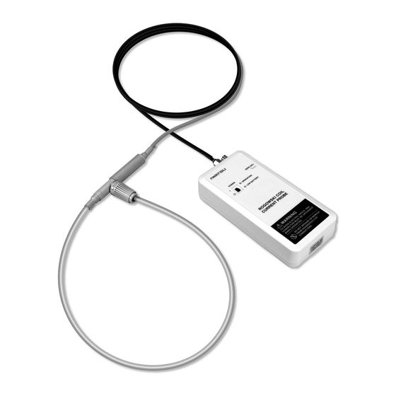
- Page 1 Instruction Manual Rogowski Coil Current Probe SS-293S/293L/294S/294L SS-295S/295L/296S/296L...
- Page 2 Ⓒ2015 IWATSU TEST INSTRUMENTS CORPORATION.All rights reserved....
-
Page 3: Table Of Contents
Contents Introduction ················································································· 1 To ensure Safe Operation ·························································· 1 Warnings ····················································································· 2 Cautions ······················································································ 5 Checking packed materials························································· 7 Components ··············································································· 7 Management of product ······························································ 8 Repair and sending instrument to be repaired ··························· 8 Cleaning of this instrument ························································· 8 Chapter 1 Overview ··································································... - Page 4 Memo...
-
Page 5: Introduction
◇ Reproduction or reprinting of the contents of this manual without prior permission from IWATSU TEST INSTRUMENTS CORPORATION is prohibited. ◇ If any question arises about this instrument, contact Iwatsu office or our sales distributors. Revision History ◇ April 2015: 1st edition... -
Page 6: Warnings
POWER switch to the O side to turn off the power to this instrument. After that, contact Iwatsu office or our sales distributors for repair. - Page 7 BNC cable of this instrument. If not, an electric shock, fire, or failure may occur. Do not use any of the cables if damaged. Contact Iwatsu office or our sales distributors for repair. • Do not modify any cable. • Do not pull on any cable.
- Page 8 POWER switch to the O side to turn off the power to this instrument. After that, contact Iwatsu office or our sales distributors for repair.
-
Page 9: Cautions
Read the following safety information. (continued) Cautions Do not expose to rapidly-changing temperature, mechanical stress, or impact. The main unit, coil, sensor and BNC cable will be damaged if exposed to these. This will be a cause of a failure. ... - Page 10 If not, an electric shock or failure may occur. We recommend that you contact Iwatsu office or our sales distributors for periodic inspection and calibration about once a year.
-
Page 11: Checking Packed Materials
Checking packed materials When receiving this instrument, check the packed materials while referring to the following “Components.” If there is a missing item or an item damaged during transportation, immediately contact Iwatsu office or our sales distributors. Components Main unit ...... -
Page 12: Management Of Product
Request a recycling company in accordance with local laws or regulations. Repair and sending instrument to be repaired If a failure occurs, send the instrument to Iwatsu office or our sales distributors. When sending an instrument to be repaired, clearly write the instrument... -
Page 13: Chapter 1 Overview
Chapter 1 Overview Chapter 1 Overview 1.1 Instrument Overview This instrument is a current probe that uses the Rogowski Coil as a sensor. It allows measurement of current in high-voltage and large-current facilities, such as train inverters, as well as in high-voltage and large-current applications such as development and maintenance of infrastructures of the automotive and other industries. -
Page 14: Features
Chapter 1 Overview 1.2 Features The following describes the features of this instrument. Target of measurement • Train inverters etc. • Development and maintenance of infrastructure facilities of the automotive and other industries Easy measurement Current in facilities (such as switchboards) can be measured easily. A thin and removable Rogowski Coil (two types of the coils, which have lengths of 300 mm and 700 mm, respectively, are available, and the maximum cross sectional diameter of the coil is 8.5 mm) -
Page 15: Usage Example
Chapter 1 Overview 1.3 Usage Example To measure current using this current probe, place a conductor to be measured through the coil loop, and detect a change in magnetic flux caused by the current flowing through the conductor with the Rogowski Coil as an electromotive force, as shown in the following usage example (conceptual illustration). -
Page 16: Chapter 2 Names And Functions Of Parts
Chapter 2 Names and Functions of Parts Chapter 2 Names and Functions of Parts 2.1 Main Unit ... -
Page 17: Names And Functions Of Parts Of Main Unit
There is a label placed on the back of the main unit. The label describes the following: • TYPE: One of the eight models, SS-293S/L, 294S/L, 295S/L, 296S/L • Peak Current: One of the current values that the above model handles, 1.2 kA, 3 kA, 6 kA, or 12 kA •... -
Page 18: Rogowski Coil Sensor Part
Chapter 2 Names and Functions of Parts 2.3 Rogowski Coil Sensor Part Current direction mark Name Description Rogowski Coil A coil for detecting the current in conductors to be measured. Forms a closed loop during measurement. Covered with an insulating outer sheath for heat resistance and insulation. -
Page 19: Chapter 3 Measurement Principle
Chapter 3 Measurement Principle Chapter 3 Measurement Principle This instrument is designed to measure the current (current waveform) in conductors to be measured. It consists of the Rogowski Coil Sensor part and the main unit (integrator). Sections 3.1 and 3.2 in this chapter describe measurement principles and functions of each part and are concluded with an explanation of a process of measuring the current (current waveform). -
Page 20: Rogowski Coil Sensor Part
Chapter 3 Measurement Principle 3.1 Rogowski Coil Sensor Part Figure 3.1 shows that the current I flows through the conductor to be measured. This section describes the principle of detecting this current by the Rogowski Coil step by step. Output voltage (V) Signal that is differential of input (Current waveform) -
Page 21: Main Unit
Chapter 3 Measurement Principle 3.2 Main Unit As illustrated in Figure 3.2, the electromotive force e induced in Section 3.1 is brought in the input part of the main unit through the sensor cable. Observation with an Main unit (in the dotted oscilloscope (not included) and other monitoring area) -
Page 22: Chapter 4 Measurement
Chapter 4 Measurement Chapter 4 Measurement 4.1 Preparation for Measurement (1) Have this instrument, a monitoring device, and a target to be measured ready. *: A monitoring device means an oscilloscope, DVM, recorder, and other devices. (2) Place four AA dry batteries in the main unit. <For batteries>... -
Page 23: Measurement Procedure
Chapter 4 Measurement 4.2 Measurement Procedure (1) Make sure that all preparations described in the previous section are completed. (2) Set up a target to be measured so that it can be used. Do not energize the target to be measured even when it is ready to be used. - Page 24 Chapter 4 Measurement The current detection polarity is shown as in the following figure. Positive polarity is output by current flowing in the direction indicated by the current direction mark shown on the joint box. Current direction mark Current to be measured Figure 4.2 Current Detection Polarity (4) Turn on this instrument (this instrument is turned on by turning the slide switch shown in the following figure to the I side and off by...
-
Page 25: Before Measurement
Chapter 4 Measurement 4.3 Before Measurement This section describes notes on accuracy and the handling of the Rogowski Coil Sensor part when measuring the current using this instrument. 4.3.1 To Achieve Accurate Measurement As explained in Chapter 3 “Measurement Principle,” the Rogowski Coil is a wire rod wound tight around a tube-like wick material, as illustrated in Figure 3.1. - Page 26 Chapter 4 Measurement 4.3.2 Resisting Voltage Guarantee Range of Rogowski Coil Sensor Part The resisting voltage guarantee range of the Rogowski Coil Sensor part is illustrated in Figure 4.4. The sensor cable’s resisting voltage guarantee range is the section covered with a gray tube (approx. 500 mm). Keep the section of the sensor cable where the resisting voltage is not guaranteed away from high-voltage parts.
- Page 27 We recommend that you replace a deformed coil or a coil with its surface damaged, in order to maintain safety and accurate measurement. Contact Iwatsu office or our sales distributors for replacement.
-
Page 28: Chapter 5 Specifications
Chapter 5 Specifications Chapter 5 Specifications 5.1 Specifications Basic specifications SS-293S/L SS-294S/L SS-295S/L SS-296S/L Sensitivity [mV/A] Peak current [kA] Peak di/dt [kA/μs] S:60/L:32 Absolute maximum di/dt Peak [kA/μs] RMS [kA/μs] to 20 MHz [−3 dB] SS-29xS Frequency bandwidth to 10 MHz [−3 dB] SS-29xL... - Page 29 Chapter 5 Specifications BNC cable (1), screw driver (1), AA dry battery (4), Accessories Instruction Manual (1), and hard case (1) Environmental characteristics Operating temperature and 0C to 40C, 80%RH or less humidity range Storage temperature and −10C to 60C, 80%RH or less humidity range ≤...
-
Page 30: Appearance
Chapter 5 Specifications 5.2 Appearance (1) Main Unit Unit: mm... - Page 31 Chapter 5 Specifications (2) Rogowski Coil Sensor Part Unit: mm...
- Page 32 Chapter 5 Specifications Memo...
- Page 33 Address : 7-41, Kugayama 1-Chome, Suginami-ku, Tokyo, 168-8511 Japan Phone : +81 3 5370 5483 Facsimile : +81 3 5370 5492 : http://www.iti.iwatsu.co.jp E-mail : info-iti@iwatsu.co.jp...
- Page 34 SS-293S/293L/294S/294L/295S/295L/296S/296L...