Table of Contents
Advertisement
Quick Links
Advertisement
Table of Contents

Related Manuals for Nellcor OxiMax N-550


Summary of Contents for Nellcor OxiMax N-550
- Page 1 N-550 Pulse Oximeter Service Manual N-550 /min /min SatSeconds...
- Page 2 To obtain information about a warranty, if any, contact Nellcor’s Technical Services Department, or your local representative. Purchase of this instrument confers no express or implied license under any Nellcor Puritan Bennett patent to use the instrument with any sensor that is not manufactured or licensed by Nellcor Puritan Bennett.
-
Page 3: Table Of Contents
C o n t e n t s Contents ........... . i Figures . - Page 4 Contents Accessing Menu Items ................33 Menu Item 1 (Trend Print) ..............33 Menu Item 2 (Trend Clear) ..............34 Menu Item 3 (Language Selection) ............34 Menu Item 4 (Baud Rate) ..............34 Menu Item 5 (EPP Mode) ..............34 Service Menu Options ..................
- Page 5 Contents Repacking in a Different Carton ................79 Specifications ..........81 Performance .......................
- Page 6 Contents Storage of Patient Data ...............108 Front Panel PCB and Controls .................109 Front Panel Display ................109 Button Interface ...................109 Index ........... 139...
- Page 7 Contents F i g u r e s Figure 1: N-550 Front Panel ................3 Figure 2: N-550 Rear Panel ................3 Figure 3: N-550 Controls ................... 9 Figure 4: Adjusting High %SpO2 Alarm Limit ..........12 Figure 5: Adjusting Low %SpO2 Alarm Limit ..........13 Figure 6: Adjusting High Pulse Rate Alarm Limit ..........
- Page 8 Contents Figure 49: Main PCB Isolation for Interface Schematic Diagram ....115 Figure 50: Main PCB DC/Battery Input and DC/DC Schematic Diagram ..117 Figure 51: Main PCB Interface and Speaker Control Schematic Diagram ..119 Figure 52: Main PCB MCU and Storage Control Schematic Diagram ....121 Figure 53: Front Panel 7-Segment Display Schematic Diagram .....123 Figure 54: Front Panel LED Display and Buttons Schematic Diagram ...125 Figure 55: Front Panel Interface and Drivers Schematic Diagram ....127...
- Page 9 Contents T a b l e s Table 1: Equipment Needed ................7 Table 2: N-550 Menu Selections ..............30 Table 3: Institutional Default Values ............... 37 Table 4: Factory Default Settings ..............38 Table 5: Problem Categories ................44 Table 6: Power Problems ................
- Page 10 Blank Page...
-
Page 11: Introduction
I n t r o d u c t i o n Warnings Warnings are identified by the WARNING symbol shown above and a line above and below the warning text. The word WARNING and all warning text are boldfaced. Warnings alert the user to potential serious outcomes (death, injury, or adverse events) to the patient or user. -
Page 12: Manual Overview
Introduction Manual Overview ® This manual contains information for servicing the Nellcor model N-550 pulse oximeter. Only qualified service personnel should service this product. Before servicing the N-550, read the operator's manual carefully for a thorough understanding of operation. WARNING: Explosion hazard. Do not use the N-550 pulse oximeter in the presence of flammable anesthetics. -
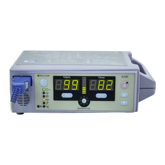
Page 13: Figure 1: N-550 Front Panel
Introduction 1 — SpO Sensor Port 12 — SatSeconds Alarm Limit Button 2 — Power On/Off Button 13 — SpO Alarm Limit Button 3 — % SpO Display 14 — Motion Indicator 4 — Pulse Amplitude Indicator 15 — Sensor Off Indicator 5 —... -
Page 14: Related Documents
N-550. Refer to the N-550 operator's manual. To understand the various Nellcor sensors that work with the N-550, refer to the individual sensor's directions for use. -
Page 15: Routine Maintenance
1. Inspect the equipment for mechanical and functional damage. 2. Inspect safety labels for legibility. If the labels are damaged, contact Nellcor’s Technical Services Department, 1.800.635.5267, or your local Nellcor representative. Functional Checks 1. If the N-550 has been visibly damaged or subjected to mechanical shock (for example, if dropped), perform the performance tests. -
Page 16: Battery
250 volts). Battery Nellcor recommends replacing the N-550's battery every two years. When the N-550 is going to be stored for two months or more, remove the battery prior to storage. To replace or remove the battery, refer to Disassembly Guide on page 55. -
Page 17: Performance Verification
P e r f o r m a n c e V e r i f i c a t i o n Introduction This section discusses the tests used to verify performance following repairs or during routine maintenance. All tests can be performed without removing the N-550 cover. -
Page 18: Performance Tests
Performance Verification Performance Tests Note: This section is written using Nellcor factory-set defaults. If your institution has preconfigured custom defaults, those values will be displayed. Factory defaults can be restored. See Menu Item 10 (Restore Factory Default Settings as Power-On Default) on page 38. -
Page 19: Power-On Self-Test (Post)
Power-On Self-Test (POST) CAUTION: If any indicator or display element does not light, or the speaker does not sound, do not use the N-550. Instead, contact qualified service personnel, your local Nellcor representative, or Nellcor's Technical Services Department, 1.800.635.5267. Note: The N-550 should complete the POST function within 12 seconds. - Page 20 Performance Verification 3. The N-550 automatically starts the Power-On Self-Test (POST), which tests N-550 circuitry and functions. CAUTION: During POST (immediately after power-up), confirm that all display segments and indicators light, and the speaker sounds a one-second pass tone. 4. While performing POST, the self-test display appears for approximately five seconds.
- Page 21 Note: The version above is only a sample. Check your N-550 for the current version installed. The version number is needed when calling Nellcor's Technical Services Department, 1.800.635.5267, or your local Nellcor representative for technical assistance. Write down the number and have it available prior to requesting technical assistance.
-
Page 22: Power-On Defaults And Alarm Limit Ranges
Performance Verification Note: In addition to serving as the POST pass verification, the POST pass tone also functions as an audible confirmation that the speaker is performing properly. If the speaker does not function, the alarm sounds cannot be heard. Power-On Defaults and Alarm Limit Ranges See Figure 3 on page 9 for the location of the N-550 controls. -
Page 23: Figure 5: Adjusting Low %Spo2 Alarm Limit
Performance Verification Note: A decimal point to the right of the value in either window display indicates that the alarm limits are not power-on default values. 7. Press the SpO Alarm Limit button two times rapidly (twice within three seconds). Verify that the N-550 emits two beeps and that the %SpO display indicates “85”... -
Page 24: Figure 6: Adjusting High Pulse Rate Alarm Limit
Performance Verification 12. Press the Pulse Rate Alarm Limit button. Verify that the N-550 emits a single beep, the pulse rate display indicates an alarm limit of “170” and that the %SpO display window shows “HI” for about 3 seconds. Figure 6: Adjusting High Pulse Rate Alarm Limit 13. -
Page 25: Figure 8: Adjusting Satseconds Alarm Limit
Performance Verification 18. Wait for POST to be completed. The %SpO and pulse rate alarm limits will be reset to the default values. 19. Press the Pulse Rate Alarm Limit button two times rapidly. Within three seconds press and hold the Adjust Up button. Verify that the pulse rate display cannot be adjusted above the upper alarm limit setting minus one point. -
Page 26: General Operation
Operation with a Live Subject on page 17. LED Excitation Test This procedure uses normal system components to test circuit operation. A Nellcor O oxygen transducer (sensor), model MAX-A, is used to examine LED intensity control. The red LED is used to verify intensity modulation caused by the LED intensity control circuit. -
Page 27: Operation With A Live Subject
Performance Verification 4. Press the Power On/Off button to turn the N-550 on. 5. Leave the sensor open with the LEDs and photo detector visible. 6. After the N-550 completes its normal power-up sequence, verify that the sensor LED is brightly lit. 7. -
Page 28: Alarm Volume Control
Performance Verification 3. Connect a Nellcor Durasensor oxygen transducer (sensor), model DS-100A, to the sensor cable. 4. Clip the DS-100A to the subject as recommended in the sensor's directions for use. 5. Press the Power On/Off button to turn the N-550 on and verify that the N-550 is operating. -
Page 29: Pulse Tone Volume Control
Performance Verification 3. Press the Adjust Up button, while holding the Alarm Silence button, to increase the alarm volume setting to a maximum value of “10.” Verify that the volume increases. 4. Press the Adjust Down button, while holding the Alarm Silence button, until a comfortable audio level is obtained. -
Page 30: Introduction
10 — Infrared LED Drive Indicator Introduction The SRC-MAX functional tester allows qualified technicians to functionally test Nellcor O technology-based pulse oximeters and OEM O technology-based monitors. The technician must perform the test setup procedure before performing tests 1 through 4. The following is a brief description of each test: •... -
Page 31: Initial Setup
Performance Verification • Test 3: Modulation — This procedure simulates an O sensor attached to a patient indicating low and high pulse strength. The test setup procedure sets up Test 3 for low pulse strength. • Test 4: Light — This procedure simulates an O sensor attached to a patient indicating low and high light level passing through the patient at the sensor site. -
Page 32: Test #1: Bpm
Performance Verification Test #1: BPM 1. Press the SRC-MAX % Pulse Rate selection button. The SRC-MAX Pulse Rate 200 LED will light. 2. The N-550 bpm will increase to 200 and stabilize at 200 bpm. The test pass criteria is 197 to 203 bpm. 3. -
Page 33: Test #2: Spo2
Performance Verification 6. The N-550 will display: • 75 %SpO2 • 60 bpm (test pass criteria is 57 to 63 bpm) • alarm • pulse amplitude indicator - low level modulation Test #2: SpO 1. Press the SRC-MAX %SpO select button. The SRC-MAX %SpO LED will light. -
Page 34: Test #3: Modulation Level
Performance Verification 6. The N-550 will display: • 75 %SpO2 (pass criteria is 73 to 77 %SpO • 60 bpm • alarm • pulse amplitude indicator - low level modulation Test #3: Modulation Level 1. Press the SRC-MAX % Modulation selection button. The SRC-MAX % Modulation LED will light. -
Page 35: Test #4: Light
Performance Verification 6. Press the SRC-MAX % Modulation selection button. The SRC-MAX % Modulation LED will light. 7. The N-550 pulse amplitude indicator will stabilize and illuminate 4 bars with each pulse beat. 8. The N-550 will display: • 75 %SpO2 •... - Page 36 Performance Verification 2. The N-550 pulse amplitude indicator will fill (10 bars) and stabilize and illuminate 4 bars with each pulse beat. 3. The N-550 will display: • 75 %SpO2 (test pass criteria is 73 to 77 %SpO • 60 bpm (test pass criteria is 57 to 63 bpm) •...
-
Page 37: Safety Tests
Performance Verification 9. Perform Test #1: BPM on page 22. The pulse amplitude indicator should indicate low level modulation. 10. Perform Test #2: SpO2 on page 23. The pulse amplitude indicator should indicate low level modulation. 11. Disconnect all equipment and turn off the N-550. Safety Tests The N-550 safety tests meet the standards of, and are performed in accordance with, IEC 60601-1 (EN 60601-1, Amendment 1, Amendment 2) and UL... - Page 38 Blank Page...
-
Page 39: Audible Alarm Settings And Service Functions
A u d i b l e A l a r m S e t t i n g s a n d S e r v i c e F u n c t i o n s Introduction This section discusses use of the service menu to reconfigure power-on default values, and how to control the behavior of the audible alarm. -
Page 40: Alarm Silence Duration
Audible Alarm Settings and Service Functions Alarm Silence Duration 1. Press and hold the Alarm Silence button. 2. Press the Adjust Up or Adjust Down button to change the duration of the alarm silence. The alarm duration can be set to 30, 60, 90, or 120 seconds, or the alarm can be turned to Off. - Page 41 Audible Alarm Settings and Service Functions Table 2: N-550 Menu Selections (Continued) Menu Sub-Menu Function Number Number EPP Mode Real Time ASCII External equipment communications In-sensor Trend Mode Event SpO Event SpO + Pulse Rate Not use in-sensor trend function RS-232 and RS-422 Nurse Call polarity (negative - low, positive - high) Positive on alarm, normally negative...
-
Page 42: Operator's Menu Options
Silence alarms (No alarm condition, both audio and visual alarms) N-550 display turned on Alarm sound selection Nellcor style Alarms sound IAW IEC 60601-1-8 Alarms sound IAW EN 475 Operator's Menu Options The menu items listed below are options that are available to the operator. - Page 43 Audible Alarm Settings and Service Functions default values that have been stored. Factory-set power-on default values are listed in Table 4 on page 38. Accessing Menu Items 1. Menu items can be accessed at any time by pressing the SpO Alarm Limit and Pulse Rate Alarm Limit buttons simultaneously until the option 1 screen is displayed.
- Page 44 Audible Alarm Settings and Service Functions Menu Item 2 (Trend Clear) When menu item 2 is selected, trend data that is available through the use of menu item 1 will be deleted when the SatSeconds Alarm Limit button is pressed and held until three beeps are heard. Menu Item 3 (Language Selection) At the present time only English is available.
- Page 45 Audible Alarm Settings and Service Functions Note: Menu items greater than 5 cannot be accessed when a valid sensor is connected to the N-550. Service Menu Options Service menu options can be accessed only when the sensor is disconnected from the N-550. Only qualified service personnel should access these options. Refer to Accessing Menu Items on page 33 for instructions on how to access the menu options and make selections within them.
-
Page 46: Figure 10: Year Month Display
Audible Alarm Settings and Service Functions When the desired option is indicated in the %SpO display, press the SatSeconds Alarm Limit button to initiate the current selection. Menu Item 8 (Time Set) If menu item 8 is selected, the N-550 Year, Month, Day, Minutes, and Seconds may be viewed and set. -
Page 47: Figure 12: Minute Second Display
Audible Alarm Settings and Service Functions Press the SatSeconds Alarm Limit button to select Hour and the next press of the SatSeconds Alarm Limit button will select the Minute Second display. See Figure 12. Figure 12: Minute Second Display Press the SatSeconds Alarm Limit button to select Second and the next press of the SatSeconds Alarm Limit button enters the selected date and time into the N-550. -
Page 48: Table 4: Factory Default Settings
Audible Alarm Settings and Service Functions Table 3: Institutional Default Values (Continued) Parameter Range Alarm silence restrictions None, sound reminder, do not allow alarms off Blip volume 0 to 10 Language English Serial port baud rate 2400, 9600, 19200 Serial port mode ASCII, external equipment communications Event in-sensor trend format , SpO... - Page 49 Audible Alarm Settings and Service Functions Table 4: Factory Default Settings (Continued) Factory Parameter Range Default Setting Pulse Rate Lower 30 bpm to Upper Alarm Limit 40 bpm Alarm Limit minus 1 Alarm Silence On or Off Reminder Alarm Silence Off, 30, 60, 90, 120 seconds 60 seconds Duration...
- Page 50 This menu item is used to select the alarm sound style. With menu item 14 selected, press the SatSeconds Alarm Limit button, then use the Adjust Up or Adjust Down button to scroll to the desired option. • Option 1 = Nellcor style • Option 2 = sound in accordance with IEC 60601-1-8 •...
- Page 51 Audible Alarm Settings and Service Functions When the desired option is indicated in the %SpO display, press the SatSeconds Alarm Limit button to set the current selection. The N-550 sounds a confirmation tone. Setting Institutional Defaults (Sample) Set alarm limits to the values established by your facility. After all alarm limits are set, you will access menu Item 9 to set the alarm limit values to institutional defaults.
- Page 52 Audible Alarm Settings and Service Functions 5. Simultaneously press SpO Alarm Limit button and Pulse Rate Alarm Limit button for over three seconds. Menu Item 1 screen appears. 6. Press the Adjust Up button until menu Item 9 is displayed. 7.
- Page 53 Who Should Perform Repairs Only qualified service personnel should open the N-550 housing, remove and replace components, or make adjustments. If your medical facility does not have qualified service personnel, contact Nellcor’s Technical Services or your local Nellcor representative. Troubleshooting Guide Problems with the N-550 are categorized in Table 5 on page 44.
-
Page 54: Table 5: Problem Categories
Troubleshooting Table 5: Problem Categories Problem Area Refer To 1. Power Power on page 44 • No power-up on AC and/or DC • Fails power-on self-test • Powers down without apparent cause 2. Buttons Buttons on page 46 • N-550 does not respond properly to buttons being pressed 3. -
Page 55: Table 6: Power Problems
Troubleshooting Table 6: Power Problems Condition Recommended Action Battery Low indicator Ensure that the N-550 is plugged into an operational lights steadily while AC outlet and the AC indicator is on. Check the fuses. The fuses are located in the Power 550 is connected to Supply PCB as indicated in Separating Top and Bottom AC and battery is fully... -
Page 56: Table 7: Button Problems
Troubleshooting Table 6: Power Problems (Continued) Condition Recommended Action Battery does not Replace battery if it is more than 2 years old. charge. Replace the battery as indicated in Battery Removal on page 68. Open the N-550 as described in Monitor Disassembly on Separating Top and Bottom Cases on page 56. -
Page 57: Table 8: Display/Alarms Problems
Troubleshooting Display/Alarms Table 8 lists symptoms of problems relating to non-functioning displays and audible tones or alarms and recommended actions. If the action requires replacement of a PCB or module, refer to Disassembly Guide on page 55. Table 8: Display/Alarms Problems Symptom Recommended Action Display values are... -
Page 58: Table 9: Operational Performance Problems
Troubleshooting Table 8: Display/Alarms Problems (Continued) Symptom Recommended Action An alarm condition Replace the Front Panel PCB. Refer to Front Case exists but no alarm Disassembly on page 58. (audible or visual) is indicated. Operational Performance Table 9 lists symptoms of problems relating to operational performance (no error codes displayed) and recommended actions. -
Page 59: Table 10: Data Port Problems
Troubleshooting Data Port Table 10 lists a symptom for data port problems and recommended actions. If the action requires replacement of the User Interface PCB, refer to Disassembly Guide on page 55. Table 10: Data Port Problems Symptom Recommended Action No printout is being The N-550 is running on battery power. -
Page 60: Table 11: Error Codes
Troubleshooting • displays a red “EEE” in the left numeric display area • displays a red error code in the left numeric display Note: Cycling the power clears the displayed error code Table 11: Error Codes Error Meaning Code front end RAM error front end ROM/code integrity error. - Page 61 Troubleshooting Table 11: Error Codes (Continued) Error Meaning Code SpO2 back end reports packet length error SpO2 back end reports message length error SpO2 back end reports packet contains unsupported Key SpO2 back end reports packet CRC error SpO2 back end reports end of packet missing SpO2 back end reports packet contains undefined key SpO2 back end reports corrupted variable SpO2 back end reports memory overflow...
- Page 62 Troubleshooting Table 11: Error Codes (Continued) Error Meaning Code Application program is corrupt Invalid FE102 version Error in the start up sequence OS multitasking service failure A state machine has received an unknown state transition The operation just attempted was not completed successfully example, Institutional Defaults could not be reset An unexpected value was received for example, an out...
- Page 63 Troubleshooting Table 11: Error Codes (Continued) Error Meaning Code BOOT application program is corrupt CRC does not match RTC was restarted Excessive restarts within 1 minute N-550...
- Page 64 Blank Page...
- Page 65 D i s a s s e m b l y G u i d e Introduction WARNING: Do not operate the N-550 after repair or maintenance has been performed until the N-550’s performance can be verified. Refer to the Performance Verification on page 7, for performance tests and safety tests.
- Page 66 Disassembly Guide WARNING: Before attempting to open or disassemble the N-550, disconnect the power cord from the N-550. CAUTION: Observe ESD (electrostatic discharge) precautions when working within the N-550. Note: Some spare parts have a business reply card attached. When you receive these spare parts, please fill out and return the card.
-
Page 67: Figure 13: N-550 Rear Panel Screws
Disassembly Guide 2. Remove the two rear panel screws. See Figure 13. Figure 13: N-550 Rear Panel Screws 3. Place the N-550 up-side down and remove the five screws holding the cases together. See Figure 14. Figure 14: N-550 Case Screws 4. -
Page 68: Figure 16: Separated Cases
Disassembly Guide 6. Carefully disconnect the two cables from the main PCB. See Figure 16 items 1 and 2. Figure 16: Separated Cases Front Case Disassembly 1. Perform the procedure Prior to Disassembly on page 56. 2. Perform the procedure Separating Top and Bottom Cases on page 56. 3. -
Page 69: Figure 17: Front Case Wiring
Disassembly Guide Figure 17: Front case Wiring 4. Disconnect the speaker wire connector, item 2, from the main PCB. 5. Disconnect the ribbon cable connector, item 3, from the front case PCB. 6. Remove the bracket screw connected to the main PCB. See Figure 18 item 1. -
Page 70: Figure 19: Front Case Bracket
Disassembly Guide 9. Remove the bracket and screw connected to the front PCB. See Figure 19 item 1. Figure 19: Front Case Bracket 10. Remove the two screws holding the speaker to the front case. See Figure 20 items 1 and 2. Figure 20: Speaker Removal 11. -
Page 71: Figure 22: Mp-506 Cable Connections
Disassembly Guide MP-506 Removal 1. Perform the procedure Prior to Disassembly on page 56. 2. Perform the procedure Separating Top and Bottom Cases on page 56. 3. Disconnect the front case SpO cable connector from the MP-506 PCB connector. See Figure 22 item 1. Figure 22: MP-506 Cable Connections 4. -
Page 72: Figure 23: Mp-506 Removal
Disassembly Guide Figure 23: MP-506 Removal Main PCB Removal 1. Perform the procedure Prior to Disassembly on page 56. 2. Perform the procedure Separating Top and Bottom Cases on page 56. 3. Disconnect the SpO cable connector from the MP-506 PCB. See Figure 17 item 1. -
Page 73: Figure 25: Front Case Mounting Screws
Disassembly Guide 5. Disconnect the ribbon cable connector, item 3, from the front case PCB. 6. Remove the bracket screw connected to the main PCB. See Figure 18 item 1. Figure 25: Front Case Mounting Screws 7. Remove the bracket screw, item 2, connected to the front PCB. 8. -
Page 74: Figure 27: Main Pcb Removed
Disassembly Guide 10. Disconnect the main PCB to front PCB cable from the main PCB connector item 2. 11. Remove the three remaining screws holding the main PCB to the top case. 12. Carefully lift the main PCB out of the top case. See Figure 27. Figure 27: Main PCB Removed Power Supply Removal 1. -
Page 75: Figure 28: Power Supply Wiring
Disassembly Guide Figure 28: Power Supply Wiring 3. Unplug the wiring harness connector from the power supply, item 1. 4. Disconnect the AC plug ground wire from the AC plug, item 2. 5. Unscrew the four screws from the power supply. See Figure 29. Figure 29: Power Supply Screws 6. -
Page 76: Figure 30: Power Supply Removed
Disassembly Guide Figure 30: Power Supply Removed Fan Removal 1. Perform the procedure Prior to Disassembly on page 56. 2. Perform the procedure Separating Top and Bottom Cases on page 56. Figure 31: Fan Wires 3. Unwrap the two fan wires, Figure 31 item 1, from the wiring harness. -
Page 77: Figure 32: Fan Bracket Removal
Disassembly Guide 4. Remove the two screws holding the fan bracket to the bottom case. See Figure 32. Figure 32: Fan Bracket Removal 5. Lift the fan and bracket out of the bottom case. See Figure 33. Figure 33: Fan and Bracket Removal 6. -
Page 78: Figure 34: Fan Screws
Disassembly Guide Figure 34: Fan Screws Battery Removal 1. Perform the procedure Prior to Disassembly on page 56. 2. Perform the procedure Separating Top and Bottom Cases on page 56. 3. Disconnect the battery wires from the battery. See Figure 35. Figure 35: Battery Connections 4. -
Page 79: Figure 36: Battery Removed
Disassembly Guide Figure 36: Battery Removed Equipotential Terminal Removal 1. Perform the procedure Prior to Disassembly on page 56. 2. Perform the procedure Separating Top and Bottom Cases on page 56. 3. Remove the AC connector ground wire from the equipotential ground terminal. -
Page 80: Figure 37: Ground Wire
Disassembly Guide Figure 37: Ground Wire 4. Remove the remaining nut and washer from the equipotential ground terminal. See Figure 38. Figure 38: Equipotential Ground Terminal 5. Remove the equipotential ground terminal from the bottom case. See Figure 39. -
Page 81: Figure 39: Equipotential Ground Terminal Removed
Disassembly Guide Figure 39: Equipotential Ground Terminal Removed N-550... - Page 82 Blank Page...
-
Page 83: Table 12: Spare Parts And Accessories
Nellcor's Technical Services provides technical assistance information and replacement parts. To obtain replacement parts, contact Nellcor's Technical Services (1.800.635.5267) or your local Nellcor representative. Refer to parts by the part names and part numbers. Spare parts and accessories, with part numbers, for the N-550 are listed on the Internet at: http://www.mallinckrodt.com/respiratory/resp/Serv_Supp/Apartweb/main/PartAcceMenu.html... - Page 84 Home Use Guide MAIN PCB to front PCB cable, 44 pin, bus cable Main PCB, 55A Membrane, USA MP-506 data cable, 14 pin, bus cable Nellcor SpO module, MP-506, version 1.8.1.0 Operator’s manual OPT MCU, PIC17C56/LCC, version 1.49 sensor, *****, neonatal...
- Page 85 Spare Parts Table 12: Spare Parts and Accessories (Continued) Item No. Description Shown in Figure 40 Quick Guide, English, Gray Quick Guide, English, USA Quick Guide, Japanese, Gray Rubber foot, SJ5003, 56 each, sheet Screw, 3 x 12, plastic, 2,000 each Serial D sub cable, 3 pin wire Service manual...
-
Page 86: Figure 40: Exploded View
Spare Parts Figure 40: Exploded View... - Page 87 General Instructions Pack the N-550 carefully. Failure to follow the instructions in this section may result in loss or damage not covered by any applicable Nellcor warranty. If the original shipping carton is not available, use another suitable carton; North American customers may call Nellcor’s Technical Services Department to...
-
Page 88: Figure 41: Packing
Packing for Shipment 1. Place the N-550 and, if necessary, accessory items in the original packaging. Figure 41: Packing 2. Place the N-550 into the shipping carton and seal the carton with packing tape. 3. Label the carton with the shipping address, return address, and RGA number. - Page 89 Packing for Shipment Repacking in a Different Carton If the original carton is not available, use the following procedure to pack the N-550: 1. Place the N-550 in a plastic bag. 2. Locate a corrugated cardboard shipping carton with a bursting strength of at least 200 pounds per square inch (psi).
- Page 90 Blank Page...
- Page 91 S p e c i f i c a t i o n s Performance Measurement Range SpO2 1% to 100% Pulse Rate 0 and 20 beats per minute (bpm) to 250 bpm Perfusion Range 0.03% to 20% Accuracy and Motion Tolerance Saturation 70 to 100% ±2 digits Without Motion...
- Page 92 Specifications Electrical Instrument Power Requirements 100 to 240 volts AC, 18 to 26 volt/amps to be compliant with IEC 60601 1 sub clause 10.2.2 Fuses qty 2, 2 A, 250 volts, slow blow, IEC (5 x 20 mm) Battery The battery provides at least two hours of battery life when new and fully charged with no alarms, no serial data, while using a pulse simulator set for 200 bpm, high light and low modulation.
- Page 93 Specifications Operation (Continued) Altitude/Barometric Pressure 390 m to 3,012 m 1,254 ft. to 9,882 ft.) 70 kPa to 106 kPa (31.3 in. Hg to 20.6 in. Hg) Relative Humidity 10% to 95% non condensing to be compliant with IEC 60601 1, sub clause 44.5 Transport and Storage (not in shipping container)
- Page 94 Specifications Sensor Power Dissipation Sensor Dissipation 52.5 mW 52.5 mW 52.5 mW 52.5 mW 52.5 mW 52.5 mW 52.5 mW Oxiband OXI 52.5 mW Oxiband OXI 52.5 mW Durasensor DS 100A OxiCliq P 52.5 mW OxiCliq N 52.5 mW OxiCliq I 52.5 mW OxiCliq A 52.5 mW...
- Page 95 Specifications Compliance Item Compliant With Equipment classification Safety Standards: IEC 60601-1 (same as EN60601-1), EN475, EN865, EN/IEC 60601-1-2:1993, CAN/CAS C22.2 No. 601.1, UL 2601-1, ISO 10993-1 Type of protection Class I (on AC power) Internally powered (on battery power) Degree of protection Type BF Applied part Mode of operation...
- Page 96 Specifications Item (Continued) Compliant With (Continued) Case surface made of non toxic IEC 60601 1, sub clause 48 materials Case resistant to heat and fire IEC 60601 1, sub clause 59.2(b) 550 power entry module fuse IEC 60601 1, sub clause 59.3 holder 550 exterior markings...
- Page 97 Specifications Safety Tests Ground Integrity 100 milliohms or less Earth Leakage Current IEC 60601 AC Line AC Line Neutral AAMI/ UL 2601 Polarity Cord Line Cord ANSI Normal Closed Closed µ 300 µA Reversed Closed Closed µ 300 µA Normal Open Closed µ...
- Page 98 Specifications Patient Risk Applied Current Power Line IEC 60601 AAMI/ AC Line Neutral Line Ground Polarity Cord UL 2601 ANSI Cord Normal Closed Closed µ µ Normal Open Closed µ µ µ µ Normal Closed Open Reversed Closed Closed µ µ...
- Page 99 D a t a P o r t I n t e r f a c e P r o t o c o l Introduction The data port, located at the rear of the N-550, provides interfacing capabilities for: •...
- Page 100 Data Port Interface Protocol 4. Press the SatSeconds Alarm Limit button to select option 5. 5. Select protocol 1 or 2 by pressing Adjust Up or Adjust Down button. 6. Press the SatSeconds Alarm Limit button to set the selection. Baud Rate Menu item 4 is used to select baud rate.
-
Page 101: Table 13: Data Port Pinouts
Data Port Interface Protocol 5. Select baud rate by pressing Adjust Up or Adjust Down button (2400, 9600, or 19200 [default]). 6. Press the SatSeconds Alarm Limit button to set the selection. Connecting To The Data Port Data is transmitted in the RS-232 and RS-422 formats. RS-232 data can be transmitted a maximum of 25 feet (7.62 meters). -
Page 102: Figure 42: Data Port Pin Layout
Data Port Interface Protocol Table 13: Data Port Pinouts (Continued) Signal Name Signal Ground Nurse Call (RS-232 level output) TXD- (RS-422 negative output) (-5 to -12 VDC with no audible alarm, 5 to 12 VDC with audible alarm) Nurse Call Common for Dry Contacts The pin layouts are illustrated in Figure 42. - Page 103 Data Port Interface Protocol Nurse Call Polarity Settings Voltage at pins Nurse Call Polarity Alarm State 10 to 11 Normally High No alarm or Alarms Silenced 5 to 12 VDC Audible Alarm -5 to -12 VDC Normally Low No alarm or Alarms Silenced -5 to -12 VDC Audible Alarm 5 to 12 VDC...
-
Page 104: Figure 43: Real-Time Printout
Data Port Interface Protocol Heading line will also be printed any time a value in the Column Heading line is changed. A real-time printout is shown in Figure 43. Note: Printouts are available only if the N-550 is running on AC power. Figure 43: Real-Time Printout Column Heading To explain the printout, it will be necessary to break it down to its key... - Page 105 Data Port Interface Protocol Printout Source Data in the highlighted box above represents the source of the printout, in this case, the N-550. Software Revision Level The next data field tells the user the software level (Version 1.0.0.0) and a software verification number (CRC XXXX).
- Page 106 Data Port Interface Protocol Actual column headings are in the third row of the Column Heading line. Patient data, from left to right, are the time that the chart was printed, the current %SpO value being measured, the current pulse rate in beats per minute (bpm), the current Pulse Amplitude (PA), and the operating status of the N-550.
-
Page 107: Table 14: Status Codes
Data Port Interface Protocol The Status column indicates alarm conditions and operating status of the N-550. The PH in this example indicates a Pulse Rate Upper alarm. The Status column can have as many as four codes displayed in one line of data. The status codes are listed in Table 14. - Page 108 Blank Page...
- Page 109 T e c h n i c a l D i s c u s s i o n Oximetry Overview The N-550 Pulse Oximeter measures functional oxygen saturation by measuring the light absorption of tissue, bone, and blood during the pulsatile cycle.
- Page 110 Technical Discussion Automatic Calibration Because light absorption by hemoglobin is wavelength dependent and because the mean wavelength of LEDs varies, an oximeter must know the mean wavelength of the sensor's red LED to accurately measure SpO . During manufacturing, the mean wavelength of the red LED is encoded in a integrated circuit in the sensor.
-
Page 111: Figure 44: Oxyhemoglobin Dissociation Curve
O advanced signal processing allows the N-550 to read through challenging motion conditions to deliver accurate saturation and pulse rate values. For a definition of motion, as applicable to the N-550, contact Nellcor's Technical Services Department. N-550... - Page 112 SpO . By having the calibration in the sensor, rather than the N-550, Nellcor is able to improve the published accuracy of many sensors, because the calibration coefficients can be tailored to each sensor. Consult the accuracy card included with the N-550 for specific accuracy information for the N-550 with different Nellcor sensors.
-
Page 113: Figure 45: Mp-506 Interface
Technical Discussion Figure 45: MP-506 Interface Table 15: MP-506 J1 Pinouts Signal DETECTOR (+) DIGICAL Ground DIGICAL 1 wire interface DETECTOR ( Inner Shield Ground No connection LED ( No connection LED (+) Outer Shield Ground N-550... -
Page 114: Table 16: Mp-506 J2 Pinouts
Technical Discussion Table 16: MP-506 J2 Pinouts Signal LOCK Input Ground Ground Reset Input Ground +12 V Power Input Analog Output TX Transmit data output from MP RX Receive data input to MP +5 V Analog Power Input CTS (Clear to Send) input to MP Ground +5 V Digital Power input Ground... -
Page 115: Figure 46: Block Diagram
Technical Discussion Block Diagram Theory Figure 46: Block Diagram The N-550 functional block diagram is shown in Figure 46. Most of the functions of the N-550 are performed on the Main PCB. Functions on the Main PCB include the SpO module, MCU, and Memory. - Page 116 Technical Discussion Power Supply PCB Theory Of Operation The N-550 uses a switch mode power supply. This Power Supply provides the DC power needed to charge the battery and to power the Main PCB. Electomagnetic Static Discharge (ESD) protection is also provided by the power supply.
- Page 117 Technical Discussion Regulated DC Power Supply The Main PCB receives the MAIN_DC unregulated voltage of 20 volts DC from the power supply, or 12.8 volts DC from the internal battery. The power supply on the Main PCB generates +5 and +12 volts DC. Controlling Hardware There is one microprocessor on the Main PCB, is a Microchips PIC17C756A.
- Page 118 Technical Discussion Patient Data is stored by the N-550 and can be downloaded to a printer through the data port provided on the back of the N-550. An in-depth discussion of the data port is covered in the Data Port Interface Protocol on page 89.
- Page 119 Technical Discussion Front Panel PCB and Controls Front Panel Display Visual patient data and N-550 status are provided by the Front Panel Display. At power up, all indicators are illuminated to allow verification of their proper operation. There are two sets of three, 7-segment displays. One set displays %SpO2 and the other displays pulse rate.
- Page 120 Blank Page...
-
Page 121: Figure 47: Battery Charger Schematic Diagram
Technical Descussion CR10 TP28 TP31 T POINT M1 SB3040 T POINT M1 B772 BAT+ CC12 810uH 2N3904 CC13 CC11 0.1uF CR11 B140 22uF 0.1uF 22uF 35VEL 35VEL +5VC LM78L05A/TO-92 BAT- CC10 CR15 VOUT 0.1uF 249K_F 10uH TP29 T POINT M1 CR12 47uF CR16... - Page 122 Technical Discussion +5VF2 120pF TP20 TP22 6N137 T POINT M2 T POINT M2 ANODE ENABLE TX2F CATHODE Vout +5VF2 +5VF2 TP57 +5VF2 120pF T POINT M2 TP56 TP23 TP21 6N137 T POINT M2 +12VF T POINT M2 T POINT M2 CON14A ENABLE ANODE...
-
Page 123: Figure 48: Main Pcb Isolation For Mp-506 Schematic Diagram
Technical Discussion +5VF1 MAX232S 6N137 120pF JDP1 ANODE ENABLE TX1F ZJYS51R5-M4PA(T) CATHODE Vout RX1F TP24 TP26 T POINT M3 T POINT M3 TX1F TP15 +5VF1 TX1F_N TP54 T POINT M3 T POINT M3 TP55 T POINT M3 6N137 120pF C118 C119 10pF N.O. - Page 124 Technical Discussion PRR3 5.6K_F +5VB PRU1 LM2675-ADJ PRR2 TP13 T POINT M4 TP12 1.5K_F T POINT M4 T POINT M4 SB3040 PRC4 PRL1 INPUT_V BDS8040D-330M 10nF PRC2 PRC5 PRD7 PRC1 PRC3 PRR5 100uF 47uF_16VEL 47uF 0.47uF PRC6 PRD1 35VEL 3216 3216 0.1uF MBRS340...
- Page 125 Technical Discussion 47uF_16VEL TP17 T POINT M5 0.47uF 0.1uF 47uF 47uF 47uF 47uF 5.1K 16VEL 16VEL 16VEL 16VEL TDA7052A TP18 T POINT M5 GND1 B140 0.1uF U17A 120pF LM324/SO CON2 820pF 100K_F 22nF TP19 TP16 GND2 T POINT M5 T POINT M5 Alarm Sound Module anteld PHONEJACK...
- Page 126 Technical Discussion +5VA +5VA B140 2.2nF 2.2nF 2.2nF 2.2nF 10nF 10nF 10nF 10nF T POINT M6 T POINT M6 +5VA LM78L05A/TO-92 Power OUT VOUT B140 3216 OSC2 TP11 RA2/SS RA3/SDI/SDA T POINT M6 RA4/RX1/DT1 RA5/TX1/CK1 2N2222A RB0/CAP1 T POINT M6 +5VB RB1/CAP2 RB2/PWM1...
- Page 127 Technical Discussion TP40 T POINT F1 FRF0 FRF1 FDIGIT 1 FDIGIT 2 FDIGIT 3 TP41 T POINT F1 FR17 FR18 FR19 FR21 FR22 FR20 FQ17 FQ20 FQ22 FQ18 FQ19 FQ21 2N2907A 2N2907A 2N2907A 2N2907A 2N2907A 2N2907A FSEG a FSEG b FSEG g FSEG c FSEG f...
- Page 128 Technical Discussion TP33 FR36 FSW1 T POINT F2 4.7K FR45 1N4148 FRB0 FRC7 FSD1 FR31 FSEG a ACLED GLED 2.7K_3216 GLED AC in (Green) Indicator FSD2 FSEG b FR32 GLED TP35 FRC6 FR38 FSW3 T POINT F2 OLED FSD3 Low Battery (Orange) Indicator 4.7K FSEG c FRB1...
- Page 129 Technical Discussion 2N2907A FSEG a FR10 2N2907A FSEG b FRF1 FRF0 FRF3 FRF2 FRE1 FRE0 FRC3 FRE2 FRC5 FRC4 FR11 FRC7 FRC6 FRB1 FRB0 FRB5 FRB4 FRB3 2N2907A FSEG c FRC2 FQ16 2N2222A FR12 FQ10 FQ11 FQ12 FQ13 FQ14 FQ15 2N2222A 2N2222A 2N2222A...
- Page 130 Technical Description Figure 56: Main PCB Parts Locator Diagram N-550...
- Page 131 Technical Description Figure 57: Front Panel Parts Locator Diagram N-550...
- Page 132 Technical Description PB-MD 15-20 R1 COMPONENT SILK PB-MD15-20 R1 Fine-Suntronix Made in Korea VR21 INLET Figure 58: Power Supply Parts Locator Diagram N-550...
- Page 133 I n d e x Symbols data port interface protocol data port problems description of N-550 pulse oximeter disassembly guide display/alarms problems AC input theory accessing menu items accessories alarm limit ranges earth leakage current alarm off enabling the data port alarm parameter being violated enclosure leakage current alarm silence...
- Page 134 Index measured versus calculated saturation POST menu item 1 (trend print) power problems menu item 10 (save factory default settings as pow- power supply PCB theory of operation er-on default) power supply removal menu item 11 (alarm silence behavior) power-on defaults and alarm limit ranges menu item 12 (silence) power-on self-test menu item 13 (all display off)
- Page 135 Index spare parts specifications battery 82 compliance 85 electrical 82 electrical, instrument 82 environmental 82 ground integrity 87 patient isolation risk current 88 patient risk applied current 88 performance 81 physical 84 safety tests 87 specifications, performance SRC-MAX storage altitude 83 barometris pressure 83 relative humidity 83 temperature 83...
- Page 136 Blank Page...
- Page 138 Nellcor Puritan Bennett Division 4280 Hacienda Drive Pleasanton, CA 94588 U.S.A. Telephone Toll Free 1.800.635.5267 Authorized Representative Tyco Healthcare UK LTD 154 Fareham Road Gosport PO13 0AS, U.K. © 2004 Nellcor Puritan Bennett Inc. All rights reserved. Rx ONLY 067857A-0204...