Table of Contents
Advertisement
Advertisement
Table of Contents
Troubleshooting

Related Manuals for Nellcor OxiMax N 5500


Summary of Contents for Nellcor OxiMax N 5500
- Page 1 Patient Monitor Service Manual...
- Page 2 SERVICE MANUAL For N5500 Patient Monitor Tyco Healthcare 15 Hampshire Street Mansfield, MA02048, U.S.A. Tyco Healthcare EMEA (Europe, Middle East and Africa) Tyco Healthcare UK Ltd. 154 Fareham Road, Gosport PO13 OAS, U.K. EU Representative Tyco Healthcare UK Ltd. 154 Fareham Road, Gosport PO13 OAS, U.K. Tel: (44) 1 329 224 114 Fax: (44) 1 329 224 390 Manufactured for Tyco Healthcare Mansfield, MA 02048, U.S.A.
- Page 3 Notice This document contains proprietary information which is protected by copyright. All Rights Reserved. Reproduction, adaptation, or translation without prior written permission is prohibited, except as allowed under the copyright laws. Warranty The information contained in this document is subject to change without notice. Tyco Healthcare makes no warranty of any kind with regard to this material, including, but not limited to, the implied warranties or merchantability and fitness for a particular purpose.
-
Page 4: Table Of Contents
Contents Figures Tables Introduction & Maintenance Introduction............................ 1 1.1 Manual Overview ........................ 3 1.2 Related Documents......................3 1.3 Description of the N5500 Patient Monitor ................3 Routine Maintenance ........................7 2.1 Cleaning..........................7 2.2 Periodic Safety and Functional Checks .................. 7 2.3 Functional Checks ....................... - Page 5 Contents Spare Parts ........................... 67 7.1 Introduction ........................67 7.2 Obtaining Replacement Parts....................67 7.3 Parts List..........................67 Packing For Shipment ........................71 8.1 General Instructions ......................71 8.2 Returning the N5500......................71 8.3 Repacking In Original Carton ....................71 8.4 Repacking In a Different Carton ..................72 Technical Information Specifications ..........................
- Page 6 Contents Figures Figure 1. N5500 Front Panel................................4 Figure 2. N5500 Rear Panel................................5 Figure 3. N5500 Right Side Panel ..............................6 Figure 4. N5500 Left Side Panel................................6 Figure 5. The access of Service Menu via Set-up menu........................29 Figure 6. Service Menu..................................30 Figure 7. Disassembly Sequence Flow Chart ..........................46 Figure 8.
-
Page 8: Introduction
Section 1: Introduction 1.1 Manual Overview 1.2 Related Documents 1.3 Description of the N5500 Patient Monitor Warnings Warnings are identified by the WARNING symbol shown above. Warnings alert the user to potential serious outcomes (death, injury, or adverse events) to the patient or user. WARNING: Explosion hazard. - Page 9 Introduction WARNING: During the safety test, AC mains voltage will be present on the applied part terminals. Exercise caution to avoid electrical shock hazard. WARNING: Do not place the N5500 into operation after repair or maintenance has been performed, until all Performance Tests and Safety Tests listed in section 3 of this service manual have been performed.
-
Page 10: Manual Overview
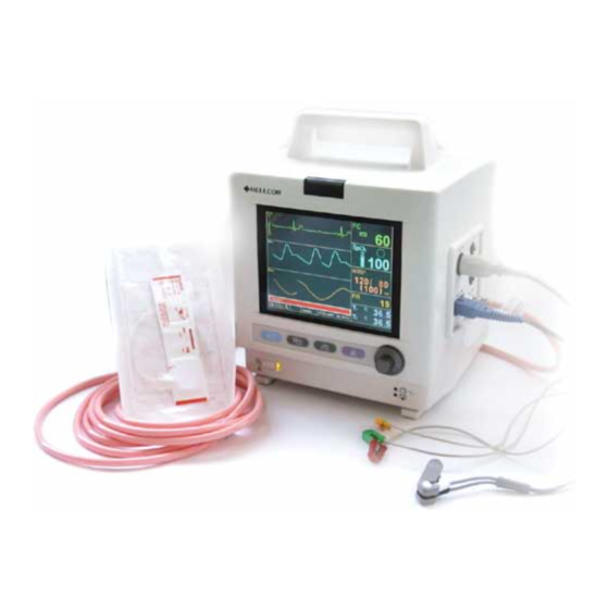
1.3 Description of the N5500 Patient Monitor The purpose and function of the Nellcor N5500 patient monitor is to monitor ECG, heart rate, noninvasive blood pressure (systolic, diastolic, and mean arterial pressures), functional arterial oxygen saturation, respiration, and temperature for adult, pediatric and neonate patients in all hospital areas and hospital- type facilities. -
Page 11: Figure 1. N5500 Front Panel
Introduction The physical and operational characteristics of the monit or are described in the operator’s manual and in the Specifications section of this manual. Figure 1 and 2 identify the displays, controls, indicators and symbols of the front and rear panels. /min %SpO 2 1 m V... -
Page 12: Figure 2. N5500 Rear Panel
Introduction 10~16V 5A RS232 T 4.0A 250V 1 2 3 4 1. External DC Power Connector 7. Data Interface Symbol 2. Equipotential Terminal (Ground) 8. Data Port Connector 3. External DC Power Symbol 9. Network Connector 4. Fuse Holder 10. Network Symbol 5. -
Page 13: Figure 3. N5500 Right Side Panel
Introduction SpO2 ECG/Respiration Connector Connector NIBP Connector Temperature Connector (T2) Temperature Connector (T1) Figure 3. N5500 Right Side Panel M4014-0 Optional thermal printer or Printer cover Figure 4. N5500 Left Side Panel N5500 Service Manual... -
Page 14: Routine Maintenance
(if required by your local institution). 1. Inspect the exterior of the N5500 for damage. 2. Inspect labels for legibility. If the labels are not legible, contact Nellcor Technical Services Department or your local Nellcor representative. -
Page 15: Functional Checks
Routine Maintenance 4. Perform the electrical safety tests detailed in Performance Verification section. If the unit fails these electrical safety tests, do not attempt to repair. Contact Nellcor Technical Services Department or your local Nellcor representative. 2.3 Functional Checks The following checks should be performed at least every 2 years by a qualified service technician. -
Page 16: Performance Verification
DOC-10 Durasensor® oxygen transducer DS-100A oxygen transducer MAX-A Temperature probes Monotherm™ simulator Nellcor SRC-MAX simulator ECG simulator METRON PS-420 or equivalent NIBP simulator Bio-Tek “BP Pump 2” or equivalent Respiration simulator METRON PS-420 or equivalent Temperature simulator medSim 300 or equivalent... -
Page 17: Performance Verification
(if required by your local institution). Before performing the battery performance test, ensure that the battery is fully charged. This section is written using Nellcor factory-set power-up defaults. If your institution has preconfigured custom defaults, those values will be displayed. - Page 18 Monitor emits three consecutively higher pitched beeps. Nellcor logo appears for a few seconds, with version numbers of the software displayed in lower left corner of display. Alarm Indicator (red) on the top of the front panel, AC power indicator (green) and Low battery indicator (green) on the right bottom of the front panel are illuminated.
- Page 19 Performance Verification 4. Verify following monitor reaction: Pulse bar begins to track artificial pulse signal from SRC-MAX. After about 10 to 20 seconds, monitor displays saturation and pulse rate as specified by simulator. Verify values are within following tolerances: Tolerance of Oxygen Saturation : ±2 % SpO Tolerance of Pulse Rate : ±3 bpm Audible alarm sounds and “Low SpO limits violated”...
- Page 20 12. Return QRS volume to a comfortable level. 3.3.4.3 LED Excitation Test This procedure uses normal system components to test circuit operation. A Nellcor oxygen transducer, model MAX-A, is used to examine LED intensity control. The red LED is used to verify intensity modulation caused by the LED intensity control circuit.
-
Page 21: Table 2. Parameter Alarm Limit Factory Defaults
Performance Verification 3.3.4.4 Restoring Power-On Default Settings The following test procedures will verify that alarms are activated at the level of factory default alarm limits and that any changed settings are saved and in effect when the user changes alarm limit settings and saves the current settings as a power default. 1.Turn the monitor on at the factory default settings. - Page 22 Performance Verification 3.3.4.5 Printer Testing (Option) If an optional printer is installe d in the N5500 monitor, the following test procedures will verify the printer performance. 1. Turn the monitor on. 2. Connect all the necessary parameter simulator to the monitor. 3.
- Page 23 Performance Verification 3.3.4.6 Serial Interface Test Perform the following procedure to test the serial port. The serial connector is Dsub-15, located on the monitor’s rear panel, identified with the data interface symbol (RS-232). 1.Connect a serial cable between the N5500 monitor and PC COM1. 2.Run “DSUB15 Test.exe”...
- Page 24 Performance Verification 3.3.5 Measurement Parameter Operation Tests 3.3.5.1 ECG Operation with an ECG Simulator 1. Press Power On/Off switch to turn monitor on. 2. Connect ECG leads to appropriate jacks on ECG simulator. 3. Connect leads to MDEC ECG cable. 4.
- Page 25 Performance Verification 10. Connect all the leads to the monitor. Select ECG menu and set ECG Lead selection to Lead I. Verify the lead selection. Repeat step 10-a for all the ECG Lead selections. 11. Set ECG Lead selection to Lead II. 12.
- Page 26 Performance Verification 3.3.5.2.1 Pressure Sensor Accuracy Test The pressure sensor accuracy test verifies the pressure accuracy of the N5500 pressure sensor. 1. Ensure Bio-Tek simulator is in Static pressure test mode. 2. NIBP Test screen is active on N5500, then select “Pressure Sensor Accuracy Test” by the knob.
- Page 27 Performance Verification 3. The N5500 displays pressure of approximately 290 mmHg automatically. 4. The test result displays at the test completion. The initial pressure value at 1 minute is displayed after the test start and the air leakage value at further 3 minutes after the 1 minute elapsed.
- Page 28 Performance Verification 3.3.5.3 Pulse Oximetry Operation with SpO simulator 1. Connect the monitor to an AC power source. 2. Turn on the monitor by pressing the Power On/Off switch. 3. Connect the DOC-10 pulse oximetry cable after the monitor completes POST. 4.
- Page 29 Performance Verification 8. Test #3: Modulation Level Press the SRC-MAX %MODULATION selection button. The SRC- MAX %MODULATION LED will light. The monitor waveform display will spike and stabilizes at a higher modulation level. iii. The monitor will display: - 90 % SpO - 60 bpm - no alarm Disconnect all equipments and turn off the monitor.
-
Page 30: Safety Tests
Performance Verification 4. Set temperature simulator as follows: Temperature: 37°C (98.0°F) Probe type: Monotherm™ Temperature Probes (Probe accuracy: ±0.1°C) 5. After normal power-up sequence, verify temperature reads 37°C ±0.1°C (98.6°F ±0.2°F if Fahrenheit is selected as temperature units). 6. Turn monitor off. Note: The accuracy of N5500 temperature measurements is ±0.1°C (±0.2°F) in the range of 25°C to 45°C and ±0.2°C in the range of 15°... -
Page 31: Table 3. Earth Leakage Current Values
Performance Verification Table 3. Earth Leakage Current Values Allowable Leakage Current (microamps) Test Condition Normal polarity Normal polarity; Neutral open 1000 Reverse polarity Reverse polarity; Neutral open 1000 Note: Earth leakage current is measured under various conditions of the AC mains and protective earth conductor. -
Page 32: Table 5. Patient Leakage Current Values
Performance Verification 3. Connect the ECG test cable between the ECG connector on the N5500 and the appropriate input connector on the analyzer. 4. Turn on the N5500. 5. Perform the patient leakage current test as recommended by the analyzer operating instructions. -
Page 33: Table 6. Patient Leakage Current Values - Mains Voltage On Applied Part
Performance Verification Note: Keep the patient test cable length as short as possible during the leakage test. Note: This test requires the same test cables for each patient connector as described in 3.4.2.3 Patient Leakage Current. 1. Configure electrical safety analyzer as recommended by analyzer operating instructions. -
Page 34: Table 7. Test Lead Combinations
Performance Verification 3. Connect the patient test lead combination in table 7 to the appropriate input connector on the electrical analyzer. 4. Turn on the N5500. 5. Perform patient auxiliary current test per table 8 as recommended by electrical analyzer’s operating instructions. 6. -
Page 36: Service Menu And Factory Default Settings
Section 4: Service menu and Factory Default Settings 4.1 Introduction 4.2 Service Menu 4.3 Demo Mode 4.4 Factory Default Settings 4.1 Introduction This section discusses use of the Service menu to configure Power-on default settings, Alarm Suspend, Alarm Silence Period, Audible Alarm Type, AC Line Frequency, Language selections, NIBP Test Mode access, and System Information to obtain service-related information about the monitor. - Page 37 Service Menu and Factory Default Settings the screen display). Press the knob. Set-up menu displays. 3. Rotate the knob to highlight Service Menu in the Set-up menu, and then press the knob to access the Service Menu. 4. Three digits displays in the Level 2 Menu as shown in Figure 5. Note: The access code is 4, 0, 2.
-
Page 38: Table 9. Service Menu
Service Menu and Factory Default Settings 11. Turn the monitor off, then power the monitor on again. Note: The monitor must be powered off upon selecting “Done” to save any changes into the monitor, and then the changes made to the Power on defaults will be in effect next time the unit is powered up. - Page 39 Service Menu and Factory Default Settings Alarm Silence Period Pressing the Alarm silence/suspend switch temporarily silences alarms for the time indicated in the Silence Period. Audible Alarm Type GN924 or IEC60601-1-8 The N5500 has two different audible alarm types, called GN924 and IEC60601-1-8. They have different tone pitch and on-off beep patterns.
-
Page 40: Table 10. Nibp Test Mode
Service Menu and Factory Default Settings Table 10. NIBP Test Mode Tests Description Pressure Sensor Accuracy Test Verifies that the pneumatic pressure sensor accuracy is within the specification. Over Pressure Test Verifies that the valve will open and the pump will be disabled if system pressure reaches the over-pressure protection point (320±10 mmHg in adult/pediatric mode, 160±5 mmHg in... -
Page 41: Demo Mode
Service Menu and Factory Default Settings 4.3 Demo Mode The purpose of Demo mode is to show a visual presentation demonstrating how the N5500 monitor works. The following procedure is set to Demo mode. 1.Turn the N5500 monitor on. 2.Rotate the knob to highlight the Set-up icon, then press the knob. Set-up menu displays. - Page 42 Service Menu and Factory Default Settings Factory Defaults Parameter Adult Pediatric Neonatal Heart Rate Tone Source Heart Rate Alarm Upper Limits 120 BPM 160 BPM 200 BPM Heart Rate Alarm Lower Limits 50 BPM 75 BPM 100 BPM C-Lock Satseconds Value In-Sensor Type %SpO %SpO...
-
Page 44: Troubleshooting
Only qualified service personnel should open the monitor housing, remove and replace components, or make adjustments in accordance with this service manual. If your medical facility does not have qualified servic e personnel, contact Nellcor Technical Services or your local Nellcor representative. -
Page 45: Troubleshooting Guide
Note: Taking the recommended actions discussed in this section will correct the majority of problems you will encounter. However, problems not covered here can be resolved by calling Nellcor Technical Services or your local Nellcor representative. All of the categories in Table 13 are discussed in the following paragraphs. -
Page 46: Table 14. Power Problems
Troubleshooting 5.5.1 Power Power problems are related to AC and/or DC. Table 14 lists recommended actions to address power problems. Table 14. Power Problems Symptom Recommended Action 1. When AC power 1. Ensure power cord is plugged into appropriate AC outlet of cord is connected to voltage and frequency. -
Page 47: Table 15. Display
Troubleshooting 5.5.2 Display Table 15 lists symptoms of problems relating to non-functioning displays, and recommended actions. If the action requires replacement of a PCB assembly or module, refer to Disassembly Guide. Table 15. Display Symptom Recommended Action 1. LCD screen is totally 1. -
Page 48: Table 16. Switches/Knob Problems
Troubleshooting 5.5.3 Switches/Knobs Table 16 lists symptoms of problems and recommended actions to address problems with the knob and front panel switches. Table 16. Switches/Knob Problems Symptom Recommended Action 1. N5500 fails to power- 1. Take steps as noted in paragraph 5.5.1. up when Power On/Off switch is pressed. -
Page 49: Table 18. Operational Performance Problems
If an error code occurs, take the following actions: 1. Turn monitor off, then on again. Note: If error code still appears, take monitor out of service and contact Nellcor Technical Services or your local Nellcor representative for advice on remedial action. -
Page 50: Table 19. Technical Error Codes
Troubleshooting Table 19. Technical Error Codes Error Codes Explanation EEE001 module RAM error EEE002 module ROM/code integrity error EEE003 module Bad CRC in communications EEE004 module Bad communication message EEE005 2 module Communication error, incorrect value EEE006 module Calibration (offset) failure EEE009 module Syntax communication error EEE010... - Page 51 Troubleshooting Error Codes Explanation EEE287 module Sensor trend data unavailable for reading by Host EEE288 module No more sensor trend data available for reading by Host EEE289 module Sensor Private label/Host sensor Key incompatible EEE700 NIBP module RAM error EEE701 NIBP module ROM error EEE702 NIBP module Different mode settings between the monit or and the...
-
Page 52: Disassembly Guide
Section 6: Disassembly Guide 6.1 General 6.2 Replacement Level Supported 6.3 Prior to Disassembly 6.4 Fuse Replacement 6.5 Battery Disassembly 6.6 Monito Disassembly 6.7 Front Case Disassembly Procedures 6.8 Rear Case Disassembly Procedures 6.9 Optional Printer Assembly/Disassembly Procedures WARNING: Performance Verification. Do not place the N5500 into operation after repair or maintenance has been performed, until all Performance Tests and Safety Tests listed in Section 3 of this service manual have been performed. - Page 53 Disassembly Guide N5500 Monitor Battery Cover Battery Front Case Rear Case LCD Bracket Side Connectors Wall A1-1 Main PCB SMPS Bracket ECG Connector A1-2 B1-1 TFT LCD Panel SMPS SpO2 Connector A1-3 B1-2 Backlight Inverter Rear Communication PCB NIBP Connector A1-4 B1-3 Alarm LED PCB...
-
Page 54: Replacement Level Supported
Disassembly Guide 6.2 Replacement Level Supported The replacement level supported for this product is to the printed circuit board (PCB) and major subassembly level. Once you isolate a suspected PCB, follow the procedures in Disassembly Guide, to replace the PCB with a known good PCB. Check to see if the trouble symptom persists, swap back the replacement PCB with the suspected malfunctioning PCB (the original PCB that was installed when you started trouble shooting) and continue troubleshooting as detected in this section. - Page 55 Disassembly Guide c. Remove a fuse from the socket, then replace a new fuse (250V/4A). Battery Fuse or External DC Fuse Replacement a. Step B2-1, SMPS disassembly b. Ensure a blown fuse F1: External DC Fuse (250V/6.3A) F2: Battery Fuse (250V/6.3A) c.
-
Page 56: Battery Disassembly
Disassembly Guide 6.5 Battery Disassembly This section describes the steps to remove the battery from the N5500 for replacement without disassembling the main case of the monitor R. Battery Disassembly a. Remove 2 screws on the lower part of the rear case, holding the Battery cover to the rear case. -
Page 57: Monitor Disassembly
Disassembly Guide 6.6 Monitor Disassembly This section describes the steps to separate the front and rear case assemblies. Before the steps A and B; a. Remove the monitor ’s 6 screws. b. Separate the front case from the rear case. c. -
Page 58: Front Case Disassembly Procedures
Disassembly Guide 6.7 Front Case Disassembly Procedures This section describes the items that may be removed on the front case assembly. A. Front Case Disassembly A1. To remove the LCD Bracket from the front case a. Disconnect the Encoder wire, the Function switch board wire and the Power switch board wire from the Main PCB. - Page 59 Disassembly Guide CAUTION: Be careful of disconnecting the LCD cable because the LCD connector cover is weak. A1-2. TFT LCD Panel Disassembly a. Remove the LCD window from the LCD panel. b. Disconnect the LCD backlight wire from the LCD panel. c.
- Page 60 Disassembly Guide A1-3. LCD Backlight Inverter Disassembly a. Disconnect the LCD backlight wire and the Inverter wire from the Backlight inverter. b. Remove 3 screws on the Backlight inverter A1-4. Alarm LED PCB Disassembly a. Disconnect the Alarm LED board wire from the Alarm LED PCB.
- Page 61 Disassembly Guide A2-1. Knob, Encoder Disassembly a. Pull the Knob straight out from the front case. CAUTION: Be careful when pulling the Knob because the Encoder may be damaged. b. Turn the Encoder to the left in order to remove the Encoder from the front case. A2-2.
- Page 62 Disassembly Guide A2-3. Power Switch PCB Disassembly a. Remove 3 screws on the Power switch PCB. A2-4. Alarm Indicator Window Disassembly a. Push the latches slightly to remove the Alarm indicator window. N5500 Service Manual...
-
Page 63: Rear Case Disassembly Procedures
Disassembly Guide 6.8 Rear Case Disassembly Procedures This section describes the steps to disassemble the rear case assembly. B. Rear Case Disassembly B1. SMPS Bracket Disassembly a. Remove 4 screws and washers on the rear case. b. Separate the rear case from the rear case assembly. - Page 64 Disassembly Guide B1-2. Rear Communication PCB Disassembly a. Remove 6 screws on the Rear communication PCB. b. Disconnect the Main board cable, the SMPS to Rear board DC wire, the Speaker wires and the Fan wire from the Rear communication PCB. B1-3.
- Page 65 Disassembly Guide b. A nut is firmly on the back of the External DC input connector. Turn the nut to the left in order to remove it. A nut is firmly on the back of the GND terminal. Turn the nut to the left in order to remove it.
- Page 66 Disassembly Guide B1-5. Cooling Fan Disassembly a. Remove 4 corner screws on the cooling fan. b. Remove the cooling fan from the SMPS bracket. B2. Analog Bracket Disassembly B2-1. SpO module and SpO2 PCB Disassembly a. Remove 3 screws on the Shield plate. N5500 Service Manual...
- Page 67 Disassembly Guide b. Remove the Shield plate from the SpO module. c. Remove 3 PCB supporters on the SpO module. d. Remove the PI cable from the SpO module. e. Remove the SpO module f. Turn down the grabbers of the Main board cable connector and the Analog board cable connector on the rear PCB.
- Page 68 Disassembly Guide h. Remove the SpO PCB. B2-2. ECG PCB Disassembly a. Disconnect the ECG wire and the Temperature wires from the ECG PCB. b. Remove 4 corner screws on the ECG PCB. c. Remove the PCB supporters on the ECG PCB.
- Page 69 Disassembly Guide b. Remove the speakers from the Analog Board bracket. C. Side Connectors Wall Disassembly a. After the SMPS bracket and the Analog Boards are disassembled, as described in B1 and B2, remove 4 corner screws fastening the Side connectors wall to the SMPS bracket.
- Page 70 Disassembly Guide b. Remove the SpO connector from the Side connectors wall. C-2. ECG Connector Disassembly a. Remove 4 corner screws on the ECG connector. b. Remove the ECG connector from the Side connectors wall. C-3. Temperature Connector Disassembly a. Turn the Temperature connector to the left.
- Page 71 Disassembly Guide C-4. NIBP Connector Disassembly a. Remove the NIBP hose from the NIBP connector. b. Turn to the left a nut fastening the NIBP connector. c. Remove the NIBP connector from the Side connectors wall. N5500 Service Manual...
-
Page 72: Optional Printer Assembly/Disassembly Procedures
Disassembly Guide 6.9 Optional Printer Assembly/Disassembly Procedures This section describes the steps that may remove an optional printer in the N5500. If you would like to install a printer, follow the reverse sequence of the procedures. B3. Printer Disassembly The rear case separated from the front case a. - Page 73 Disassembly Guide B3. Printer Disassembly c. Remove 2 screws inside the Printer door. d. Remove the Printer. N5500 Service Manual...
-
Page 74: Spare Parts
Figure 8. 7.2 Obtaining Replacement Parts Nellcor Technical Service provides technical assistance information and replacement parts. To obtain replacement parts, contact Nellcor or your local Nellcor representative. Refer to parts by the part names and part numbers. 7.3 Parts List Nellcor Technical Service provides technical assistance information and replacement parts. - Page 75 Spare Parts Figure 8. N5500 Exploded View N5500 Service Manual...
-
Page 76: Table 20. N5500 Parts List
E4077-0 External DC Input Connector E8004-0 AC Inlet Fuse (250V/ T4A) E8005-0 Battery Fuse (250V/ T6.3A) E9004-0 Speaker 30pi E9003-0 Speaker 50pi M0001-0 NELLCOR SpO Module M0003-0 Colin NIBP Module M2005-0 SMPS M4012-0 LCD (6.4” TFT) M4014-0 Printer M6005-0 Battery... - Page 77 Spare Parts Item Part Code Description T4083-0 Analog BD Bracket T4084-0 AC Inlet Bracket T4085-0 Bridge Bracket T4086-0 Shield Plate W0019-0 PI Cable W0062-0 Colin Inner Hose W0064-0 Main BD Cable W0065-0 NIBP Cable W0066-0 Analog BD Cable W0067-0 Function SW BD Wire W0068-0 Backlight Inverter Wire W0069-0...
-
Page 78: Packing For Shipment
Pack the monitor carefully. Failure to follow the instructions in this section may result in loss or damage not covered by the Nellcor warranty. If the original shipping carton is not available, use another suitable carton; North American customers may call Nellcor Technical Services to obtain a shipping carton. -
Page 79: Repacking In A Different Carton
Packing For Shipment 8.4 Repacking In a Different Carton If the original carton is not available, use the following procedure to pack the N5500: 1. Place the monitor in a plastic bag. 2. Locate a corrugated cardboard shipping carton with at least 200 pounds per square inch (psi) bursting strength. -
Page 80: Technical Information Specifications
Section 9: Specification 9.1 Display 9.2 Controls 9.3 Alarms 9.4 Physical Characteristics and Printer 9.5 Electrical 9.6 Environmental 9.7 Measuring Parameters 9.8 Trends 9.9 Compliances 9.1 Display Screen Size 130.56 mm × 97.92 mm (6.425 inch) Liquid Crystal Display (LCD) Color, Screen Type/Color Cold Cathode Fluorescent Backlit Resolution... -
Page 81: Electrical
Specification 9.5 Electrical Instrument AC Mains Power Requirements 100Vac to 240Vac, 50 Hz/60 Hz, 63 to 110 VA, 1A Max qty 2, 4.0 A, 250 volts, slow-blow, IEC (5×20 mm) Fuses Battery The battery provides 1 hour of battery operation when fully charged with no printing and one NIBP measurement per 5 minutes at typical 25°... -
Page 82: Measurement Parameters
Specification 9.7 Measurement Parameters Heart Rate Measurement Range 20 BPM to 250 BPM Accuracy ±3 BPM or ±5%, whichever is greater ECG (Electrocardiograph) Leads 3 / 5 Lead, user selectable I, II, III, V, aVR, aVL, aVF Lead Off Detection Detected and displayed Input Input Dynamic Range... - Page 83 Specification NIBP Pulse Rate Pulse Rate Range Adult/Pediatric 30 BPM to 180 BPM Neonatal 30 BPM to 240 BPM Pulse Rate Accuracy ±2 BPM or ±2%, whichever is greater NIBP (Non-Invasive Blood Pressure) Technique Oscillometric Measurement Measurement modes AUTO, MANUAL and STAT AUTO Mode Automatic BP measurements at intervals of 1, 3, 5, 10, 15, 30, 60, and 90 minutes...
-
Page 84: Trends
OxiMax MAX-N sensors with the N5500. Saturation accuracy will vary by sensor type. Applicability(accuracy with motion): OxiMax sensors. Specification applies to monitor performance and was validated with Biotek and Nellcor simulators Temperature Probe Type Thermistor probe (Monotherm™ temperature probes) -
Page 85: Compliance
Specification 9.9 Compliance Item Compliant with Classification Class I (on AC power) Internally powered (on battery power) Type of protection Type CF – Applied part Mode of operation Continuous Resistant to liquid Class IPX1 Drip-proof equipment General Safety IEC60601-1:1998+A1:1991+A2:1995 General requirements for Safety and Essential Performance IEC60601-2-49:2001 Particular requirements for the Safety of Multifunction patient equipment IEC60601-1-1:2000 Safety requirements for medical electrical systems... - Page 86 Specification Item Compliant with Electromagnetic IEC 60601-1, sub clause 36, IEC/ Compatibility IEC60601-1-2:1993 Electromagnetic compatibility-requirements & test IEC61000-3-2 Harmonic Emmision IEC61000-3-3 Voltage Fluctations/Fliker Emission IEC61000-4-2 Electrostatic Discharge IEC61000-4-3 Radiated RF electromagnetic field IEC61000-4-4 Electrical fast transient/burst IEC61000-4-5 Surge current CISPR 11 (EN55011) RF Emissions Group 1, Class B Reliability IEC60068-2-6, IEC60068-2-34 Environmental testing -Vibration IEC60068-2-27 Environmental testing - Shock...
-
Page 88: System Processing Description
Section 10: System Processing Description 10.1 System Overview 10.2 System Block Diagram 10.3 ECG Processing 10.4 NIBP Processing 10.5 SpO2 Processing 10.6 Respiration Processing 10.7 Temperature Processing 10.1 System Overview The N5500 patient monitor is a multi-function monitor for use on adult , pediatric and neonatal patients;... - Page 89 System Processing Description User Control UNIT Thermal Printer UNIT Serial General Purpose Port Interface Interface General Purpose Port Interface Power UNIT System Bus Interface Processor UNIT Communication UNIT SOUND UNIT General Purpose Port Interface Serial System Bus Interface Interface GUI UNIT NIBP UNIT Figure 10.
- Page 90 System Processing Description Unit Description l Power unit : consists of power entry module, SMPS, battery charger, battery, external DC input and DC/DC unit. DC 10 - 16V Entry SMPS OUTPUT Status AC 100-250V 50Hz/60Hz DC10 - 19V Power Entry Input SMPS Module...
- Page 91 System Processing Description l Sound unit : consists of 8bit PIC micom, 2-channel amplifiers and speaker. Volume Frequency PWM OUT Control to Voltage Conversion Alarm Audio AMP 1 Speaker Sound Pulse PIC 16C63A Sound Pulse Pulse Tone Audio AMP 2 Frequency Volume Speaker...
- Page 92 System Processing Description l NIBP unit : measures non-invasive blood pressure data. NIBP Asyncronous Serial Communication with Communication UNIT Module Figure 19. NIBP Unit Block Diagram l ECG unit : measures electrocardiographic waveform data. Patient Isolation Isolation DC +/-5V DC +5V Isolation DC/DC Lead off detector , Instrument AMP,...
- Page 93 System Processing Description l Temperature unit : measures temperature data. Patient Isolation Isolation DC +/-5V, +/-12V DC +5V Isolation DC/DC Temperature Probe Constant Crrent Source AMP & Filter Analog to Digital PIC16C65B_P Reference Converter (MCP3204) Temperature Probe Constant Crrent Source AMP &...
-
Page 94: Ecg Processing
System Processing Description 10.3 ECG Processing The measurement of the skin surfaces electrocardiogram is based on the electrical signals on the skin surface, produced as the heart muscle contracts and relaxes. The signals are detected by electrodes placed on the patient body. The information on heart activity carried by these signals varies with the placing of the electrodes. - Page 95 System Processing Description Oscillometric Response Distole Systole (Pressure Pulses) TIME Systole Cuff Pressure Distole TIME Overall Accuracy Discussion Overall system accuracy shall be determined by considering various influences of the pressure sensor accuracy, motion artifacts, other artifact created by pressure valve, technical errors of electrical components, and the origin error of oscillometric method.
-
Page 96: Spo2 Processing
System Processing Description B. For data collection and the data analysis, Bland-Altman Plot is used. C. On the systolic, diastolic, and MAP, the Deltas of all measurements shall be met under +/- 5mmHg of mean difference (MD), and +/- 8mmHg of standard deviation (SD). - Page 97 System Processing Description infrared light into an arteriolar bed and measuring changes in light absorption during the pulsatile cycle. Red and infrared low-voltage light-emitting diodes (LED) in the oximetry sensor serve as light sources; a photo diode serves as the photo detector. Because oxyhemoglobin and deoxyhemoglobin differ in light absorption, the amount of red and infrared light absorbed by blood is related to hemoglobin oxygen saturation.
-
Page 98: Respiration Processing
= × 100 100 – (%carboxyhemoglobin + %methemoglobin) OxiMax Technology The N5500 SpO monitoring is designed to use Nellcor brand sensors, which integrate the technology. These sensors can be identified by their deep blue plug color. All sensors contain a memory chip carrying information about the sensor which the monitor needs for correct operation, including the sensor’s calibration data,... -
Page 99: Temperature Processing
System Processing Description pair of electrodes is determined by dividing the voltage difference between the two electrodes by the current that passes between them. When the electrodes are placed on the actual structure, respective structures change. A low-level excitation signal is applied to these leads, and the variation of the thoracic impedance caused by the breathing is sensed and processed for display and measurement. - Page 101 N5500 Service Manual Revision: A3 Part Number: MDR05002-A7009-0 Printed in Korea Copyright © 2003 Tyco Healthcare. All rights reserved.