Table of Contents
Advertisement
Quick Links
SERVICE MANUAL
NPB-190 Pulse Oximeter
Caution: Federal law (U.S.) restricts this device to sale by or on the order of a physician.
To contact Mallinckrodt's representative: In the United States, call 1.800.635.5267 or 314.654.2000; outside of the United
States, call your local Mallinckrodt representative.
0123
1999 Mallinckrodt Inc. All rights reserved.
033925E-0599
Advertisement
Table of Contents
Troubleshooting

Related Manuals for Nellcor NPB-190


Summary of Contents for Nellcor NPB-190
- Page 1 NPB-190 Pulse Oximeter Caution: Federal law (U.S.) restricts this device to sale by or on the order of a physician. To contact Mallinckrodt’s representative: In the United States, call 1.800.635.5267 or 314.654.2000; outside of the United States, call your local Mallinckrodt representative.
- Page 2 To obtain information about a warranty, if any, for this product, contact Mallinckrodt Technical Services or your local Mallinckrodt representative. Purchase of this instrument confers no express or implied license under any Mallinckrodt patent to use the instrument with any sensor that is not manufactured or licensed by Mallinckrodt.
-
Page 3: Table Of Contents
List of Tables Table Of Contents ..................List Of Figures..................List Of Tables..................Section 1: Introduction ................Manual Overview................NPB-190 Pulse Oximeter Description.......... Power-On Self Test..............Related Documents..............Section 2: Routine Maintenance..............Cleaning ..................Periodic Safety and Functional Checks ........ -
Page 4: Table Of Contents
Table of Contents Repacking in Original Carton ............Repacking in a Different Carton........... Section 9: Specifications................General ..................Electrical..................Physical Characteristics ............... Environmental ................Alarms ..................Factory Default Settings ............... Performance ................Appendix (Serial Port Interface Protocol)..........Introduction .................. Enabling the Serial Port..............Connecting to the Serial Port ............ -
Page 5: List Of Figures
Table of Contents LIST OF FIGURES Figure 1-1: NPB-190 Front Panel..............Figure 1-2: NPB-190 Rear Panel ..............Figure 3-1: NPB-190 Controls............... Figure 3-2: Self-Test Display................. Figure 3-3: Adjusting High %SpO2 Alarm Limit ..........Figure 3-4: Adjusting Low %SpO2 Alarm Limit .......... -
Page 6: List Of Tables
Table of Contents LIST OF TABLES Table 3-1: Dynamic Operating Range............Table 3-2: Earth Leakage Current Limits ............. 3-10 Table 3-3: Enclosure Leakage Current Limits..........3-11 Table 3-4: Patient Leakage Current Limits ..........3-12 Table 3-5: Patient Leakage Current Test Configurations - Mains Voltage on the Applied Part ............ -
Page 7: Section 1: Introduction
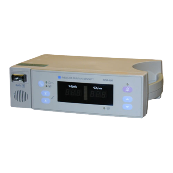
Digital displays are provided for oxygen saturation and pulse rate, and a 10- segment LED bar indicates pulse amplitude. High and low alarm limits for saturation and pulse rate can be adjusted by the operator. The NPB-190 can operate on AC or a rechargeable internal battery power. The controls and... -
Page 8: Power-On Self Test
2. AC Connector 5. Voltage Selector Switch 3. Serial Port POWER-ON SELF TEST When the NPB-190 is turned on it will perform a POST (Power On Self Test). During POST the following sequence should occur: • All indicator lights illuminate •... -
Page 9: Related Documents
To perform test and troubleshooting procedures and to understand the principles of operation and circuit analysis sections of this manual, you must know how to operate the monitor. Refer to the NPB-190 operator’s manual. To understand the various Nellcor sensors that work with the monitor, refer to the individual sensor... -
Page 11: Section 2: Routine Maintenance
BATTERY Mallinckrodt recommends replacing the instrument battery every 2 years. When the NPB-190 is going to be stored for 3 months or more remove the battery. To replace or remove the battery, refer to Section 6, Disassembly Guide. If the NPB-190 has been stored for more than 30 days, charge the battery as described in paragraph 3.3.1. -
Page 13: Section 3: Performance Verification
If the NPB-190 fails to perform as specified in any test, repairs must be made to correct the problem before the monitor is returned to the user. -
Page 14: Figure 3-1: Npb-190 Controls
Limit Limit Down Figure 3-1: NPB-190 Controls Note: Refer to Figure 3-1, NPB-190 Controls, when following the instructions listed below. 3.3.2.1 Power-On Self-Test Connect the monitor to an AC power source. Verify that the AC Power/Battery Charging indicator is lit. -
Page 15: Figure 3-2: Self-Test Display
If no sensor is connected a 1 second POST beep sounds, 3 dashes are displayed in each window and the Pulse Search LED is off. The NPB-190 begins normal operation if a sensor is connected. Without a sensor the monitor will be in the idle mode (3 dashes in each window). -
Page 16: Figure 3-5: Adjusting High Heart Rate Alarm Limit
Section 3: Performance Verification Press the Upper Alarm Limit button. Press and hold the Adjust Down button. Verify that the %SpO display reduces to a minimum of “85”. Note: A decimal point to the right of the value in either display indicates that the alarm limits are not power-on default values. - Page 17 Section 3: Performance Verification 10. Press the Power On/Standby button to turn the unit off. Turn the unit back 11. Press and release the Upper Alarm Limit button. Verify that the %SpO display indicates an alarm limit of “100”. 12. Press and release the Lower Alarm Limit button. Verify that the %SpO display indicates an alarm limit of “85”.
-
Page 18: Figure 3-7: Alarm Silence Duration
Section 3: Performance Verification The pulse blip bar begins to track the artificial pulse signal from the SRC-2. The pulse tone is heard. Zeroes are displayed in the %SpO and pulse rate displays. After about 10 to 20 seconds, the monitor displays oxygen saturation and pulse rate as specified by the tester. -
Page 19: Figure 3-8: Alarm Volume Display
Connect the SRC-2 to the NPB-190 and turn the NPB-190 on. Place the SRC-2 in the RCAL 63/LOCAL mode. Set the SRC-2 as indicated in Table 3-1. Verify that the NPB-190 readings are within the indicated tolerances. Allow the monitor several seconds to stabilize the readings. -
Page 20: Table 3-1: Dynamic Operating Range
Section 3: Performance Verification Table 3-1: Dynamic Operating Range SRC-2 Settings NPB-190 Indications RATE LIGHT MODULATION SpO2 Pulse Rate HIGH2 79 - 83* 37 - 39* HIGH1 HIGH 79 - 83* 110 - 114 79 - 83* 198 - 204*... -
Page 21: Safety Tests
15 to 30 seconds. Verify that the saturation and heart rates are reasonable for the subject. SAFETY TESTS NPB-190 safety tests meet the standards of, and are performed in accordance with, IEC 601-1 (EN 60601-1, Second Edition, 1988; Amendment 1, 1991-11, Amendment 2, 1995-03) and UL 2601-1 (August 18, 1994), for instruments classified as Class 1 and TYPE BF and AAMI Standard ES1 (ANSI/AAMI ES1 1993). -
Page 22: Table 3-2: Earth Leakage Current Limits
Section 3: Performance Verification • Ground Integrity • Electrical Leakage 3.4.1 Ground Integrity This test checks the integrity of the power cord ground wire from the AC plug to the instrument chassis ground. The current used for this test is < 6V RMS 50 or 60 Hz and 25 A. -
Page 23: Table 3-3: Enclosure Leakage Current Limits
Section 3: Performance Verification AAMI/ANSI is 120 VAC 60 Hz, and for IEC 601-1 the applied voltage is 264 VAC 50 to 60 Hz. Connect the monitor AC plug to the electrical safety analyzer as recommended by the analyzer operating instructions. Place a 200 cm foil in contact with the instrument case making sure the foil is not in contact with any metal parts of the enclosure that may be grounded. -
Page 24: Table 3-4: Patient Leakage Current Limits
Section 3: Performance Verification Table 3-4: Patient Leakage Current Limits AC LINE NEUTRAL POWER LINE IEC 601-1 AAMI/ANSI POLARITY LINE GROUND CABLE STANDARD Normal Closed Closed 100 µA 10 µA Normal Open Closed 500 µA 50 µA Normal Closed Open 500 µA 50 µA Reverse... -
Page 25: Section 4: Audible Alarm Settings & Service Menu
AUDIBLE ALARM SETTINGS The following paragraphs describe how to change the behavior of the audible alarm. Operators can select the volume of the alarm and the duration of alarm silence. Controls for the NPB-190 are shown in Figure 4-1. On/Standby Alarm silence... -
Page 26: Service Menu
Section 4: Audible Alarm Settings & Service Menu After 3 seconds, while still pressing the Alarm Silence button, the Adjust Up or Adjust Down button can be used to select alarm volumes from 1 to 10. Select a level that is suitable for the monitor’s location. SERVICE MENU The menu items listed below should be accessed only by a qualified service technician. -
Page 27: Table 4-1: Factory Default Settings
Section 4: Audible Alarm Settings & Service Menu 4.3.3 Menu Item 2 (Return to Default Settings) Menu item 2 resets the monitor to factory default settings as shown in table 4-1. Table 4-1: Factory Default Settings Parameter Default Value SpO2 High 100% SpO2 Low Pulse rate High... - Page 28 Limit button to save the current selection. Three tones will sound to indicate that the change has been accepted. 4.3.8 Menu Item 7 Do not use. For use by Mallinckrodt Customer Service Engineer. 4.3.9 Menu Item 8 Do not use. For use by Mallinckrodt Customer Service Engineer.
-
Page 29: Section 5: Troubleshooting
5.6 Troubleshooting Guide 5.7 Error Codes INTRODUCTION This section explains how to troubleshoot the NPB-190 if problems arise. Tables are supplied that list possible monitor difficulties, along with probable causes, and recommended actions to correct the difficulty. HOW TO USE THIS SECTION Use this section in conjunction with Section 3, Performance Verification, and Section 7, Spare Parts. -
Page 30: Troubleshooting Guide
Section 5: Troubleshooting TROUBLESHOOTING GUIDE Problems with the NPB-190 are separated into the categories indicated in Table 5-1. Refer to the paragraph indicated for further troubleshooting instructions. Note: Taking the recommended actions discussed in this section will correct the majority of problems you will encounter. However, problems not covered here can be resolved by calling Mallinckrodt Technical Services or your local representative. -
Page 31: Table 5-2: Power Problems
Table 5-2: Power Problems Condition Recommended Action 1. BATTERY LOW 1. Ensure that the NPB-190 is plugged into an operational AC indicator lights outlet and the AC indicator is on. steadily while NPB- 2. Check the fuses. The Power Entry Module contains the 190 is connected to fuses as indicated in paragraph 6.3 and Figure 6-3 of the... -
Page 32: Table 5-3: Button Problems
2. If the buttons still do not work, replace the UIF PCB. buttons. 1. Check the connection between the membrane panel 2. The NPB-190 turns on and J5 of the UIF PCB. but does not respond to any of the buttons. -
Page 33: Table 5-5: Operational Performance Problems
Amplitude indicator is 2. An electrosurgical unit (ESU) may be erratic. interfering with performance: ñ Move the NPB-190 and its cables and sensors as far from the ESU as possible. ñ Plug the NPB-190 and the ESU into different AC circuits. -
Page 34: Table 5-6: Serial Port Problems
Section 5: Troubleshooting 5.6.5 Serial Port Table 5-6 lists symptoms of problems relating to the serial port and recommended actions. If the action requires replacement of the PCB, refer to Section 6, Disassembly Guide. Table 5-6: Serial Port Problems Condition Recommended Action 1. -
Page 35: Error Codes
Section 5: Troubleshooting ERROR CODES An error code will be displayed when the NPB-190 detects a non-correctable failure. When this occurs, the unit will stop monitoring, sound a low priority alarm that cannot be silenced, clear patient data from the display, and display an error code. -
Page 37: Section 6: Disassembly Guide
6.7 Power Entry Module (PEM) Removal/Installation 6.8 Power Supply Removal/Installation 6.9 Display PCB Removal/Installation 6.10 UIF PCB Removal/Installation 6.11 Alarm Speaker Removal/Installation INTRODUCTION The NPB-190 can be disassembled down to all major component parts, including: • PCBs • Battery •... -
Page 38: Fuse Replacement
Section 6: Disassembly Guide FUSE REPLACEMENT Complete the procedure in paragraph 6.2. Disconnect the power cord from the back of the monitor. Remove the fuse drawer from the Power Entry Module by pressing down on the tab in the center and pulling the drawer out as shown in Figure 6-1. Figure 6-1: Fuse Removal Put new 0.5 amp fuses in the drawer and reinsert the drawer in the power module. -
Page 39: Monitor Disassembly
Section 6: Disassembly Guide MONITOR DISASSEMBLY Caution: Observe ESD (electrostatic discharge) precautions when disassembling and reassembling the NPB-190 and when handling any of the components of the NPB-190. Set the NPB-190 upside down, as shown in Figure 6-2. Corner screws Figure 6-2: NPB-190 Corner Screws Remove the four corner screws. -
Page 40: Monitor Reassembly
Place the top case over the bottom case and align the four outside screw posts and close the monitor. Caution: When reassembling the NPB-190, hand tighten the screws that hold the cases together to a maximum of 10 inch-pounds. Over-tightening could strip out the screw holes in the top case, rendering them unusable. -
Page 41: Battery Replacement
Figure 6-4: Battery Removal The lead-acid battery is recyclable. Do not dispose of the battery by placing it in the regular trash. Dispose of properly according to state, local or other applicable regulations, or contact Mallinckrodt Technical Services to return for disposal. Installation Connect the leads to the battery. -
Page 42: Power Entry Module (Pem) Removal/Installation
Section 6: Disassembly Guide Turn the monitor on and verify proper operation. POWER ENTRY MODULE (PEM) REMOVAL/INSTALLATION Removal Complete the procedure in paragraphs 6.2 and 6.4. While pushing the top of the PEM in from the outside of the case, gently push the case to the outside and lift up on the PEM. -
Page 43: Power Supply Removal/Installation
Section 6: Disassembly Guide Position the ground line from the PEM so that it does not come into contact with components on the Power Supply PCB. Complete procedure in paragraph 6.5. POWER SUPPLY REMOVAL/INSTALLATION Removal Complete the procedure described in paragraphs 6.2 and 6.4. Disconnect the leads from the battery. -
Page 44: Figure 6-7: Power Supply
Section 6: Disassembly Guide Figure 6-7: Power Supply Installation Reconnect the AC leads. The wire from the Power Supply labeled “N” goes to the terminal labeled “N” on the PEM. The wire from the power supply labeled “L” connects to the terminal labeled “L” on the PEM. Place the Power Supply in the bottom case. -
Page 45: Display Pcb Removal/Installation
Section 6: Disassembly Guide DISPLAY PCB REMOVAL/INSTALLATION Removal Complete the procedure described in paragraphs 6.2 and 6.4. Lift the Display PCB up to remove it from the top case (Figure 6-8). Grounding clip Figure 6-8: Display PCB Installation Slide the Display PCB into the grooves in the top case, being careful to align the male pins from the Display PCB to connector J4 on the UIF PCB. -
Page 46: 6.10 Uif Pcb Removal/Installation
Section 6: Disassembly Guide 6.10 UIF PCB REMOVAL/INSTALLATION Removal Complete the procedure described in paragraphs 6.2 and 6.4. Lift the Display PCB up to remove it from the top case (Figure 6-8). Disconnect the keypad ribbon cable from J5 of the UIF PCB (Figure 6-8). J5 is a ZIF connector, lift up on the outer shell until it clicks, then remove the ribbon cable from the connector. -
Page 47: 6.11 Alarm Speaker Removal/Installation
Section 6: Disassembly Guide Installation Caution: When installing the UIF PCB, hand-tighten the five screws to a maximum of 10 inch-pounds. Overtightening could strip out the inserts in the top case, rendering them unusable. Place the UIF PCB in the top case. Install the five screws in the UIF PCB. -
Page 48: Figure 6-10: Alarm Speaker
Section 6: Disassembly Guide Connect speaker wires to J3 connector Figure 6-10: Alarm Speaker Installation Slide the speaker into the plastic holding clip provided in the top housing. Connect the speaker wire harness to J3 on the UIF PCB. Complete the procedure paragraph 6.5. 6-12... -
Page 49: Section 7: Spare Parts
Power Cord (not shown) U.S. 071505 International 901862 U.K. 901863 Figure 7-1 shows the NPB-190 expanded view with item numbers relating to the spare parts list. Note: Some spare parts have a business reply card attached. When you receive these spare parts, please fill out and return the card. - Page 50 Section 7: Spare Parts Figure 7-1: NPB-190 Exploded View...
-
Page 51: Section 8: Packing For Shipment
GENERAL INSTRUCTIONS Pack the monitor carefully. Failure to follow the instructions in this section may result in loss or damage not covered by the Mallinckrodt warranty. If the original shipping carton is not available, use another suitable carton; North American customers may call Mallinckrodt Technical Services Department to obtain a shipping carton. - Page 52 Section 8: Packing for Shipment Figure 8-1: Repacking the NPB-190 Place in shipping carton and seal carton with packaging tape. Label carton with shipping address, return address and RGA number.
-
Page 53: Repacking In A Different Carton
Section 8: Packing for Shipment REPACKING IN A DIFFERENT CARTON If the original carton is not available, use the following procedure to pack the NPB-190: Place the monitor in a plastic bag. Locate a corrugated cardboard shipping carton with at least 200 pounds per square inch (psi) bursting strength. -
Page 55: Section 9: Specifications
SECTION 9: SPECIFICATIONS 9.1 General 9.2 Electrical 9.3 Physical Characteristics 9.4 Environmental 9.5 Alarms 9.6 Factory Default Settings 9.7 Performance GENERAL Designed to meet safety requirements of: UL 2601-1 CSA-C22.2 No. 601-1-M90, IEC 601-1 (Class I, type BF) EMC per EN60601-1-2 ELECTRICAL Protection Class Class I: per IEC 601-1, clause 2.2.4... -
Page 56: Physical Characteristics
Section 9: Specifications PHYSICAL CHARACTERISTICS Dimensions 3.3 in H x 10.4 in W x 6.8 in D 8.4 cm H x 26.4 cm W x 17.3 cm D Weight 5.5 lb 2.5 kg ENVIRONMENTAL Operating Temperature 5°C to 40°C (+41°F to +104°F) Storage Temperature Boxed -20°C to +70°C (-4°F to +158°F) -
Page 57: Performance
Section 9: Specifications PERFORMANCE Measurement Range 0–100% Pulse/Heart Rate: 20–250 bpm Accuracy Adult: 70–100% ± 2 digits 0–69% unspecified Neonate: 70–100% ± 3 digits 0–69% unspecified Accuracies are expressed as plus or minus “X” digits (saturation percentage points) between saturations of 70-100%. This variation equals plus or minus one standard deviation (1SD), which encompasses 68% of the population. -
Page 59: Appendix (Serial Port Interface Protocol
A5 Nurse call INTRODUCTION When connected to the serial port on the back of the NPB-190, a real-time printout can be obtained. Data lines are printed at 2 second intervals. Column headings will be printed after every 25 lines, or if one of the values in the column heading changes. -
Page 60: Figure A-1: Serial Port Pin Layout
Every 25th line will be a column heading line. A column heading line will also be printed any time a value in the column heading line is changed. A real-time printout is shown below in Figure A-2 NPB-190 Version 1.0.0 CRC XXXX... -
Page 61: Alarm Limits
30-100% PR Limit: 100-180 bpm Time Tag %SpO2 PR (bpm) Status Data in the highlighted box above represents the source of the printout, in this case the NPB-190. Software Revision Level NPB-190 Version 1.0.0 CRC XXXX SpO2 Limit: 30-100% PR Limit: 100-180 bpm... -
Page 62: Table A-2: Status Codes
Time Tag does not represent a real-time clock. The number beneath the Time Tag heading represents time, in seconds, since the unit was initialized at the factory. This number will increase in size throughout the life of the monitor. Patient Data NPB-190 Version 1.0.0 CRC XXXX SpO2 Limit:... -
Page 63: Nurse Call
Appendix NURSE CALL A Nurse Call signal can be obtained by connecting to the serial port. This function is only available when the instrument is operating on AC power. Nurse Call will be disabled when the unit is operating on battery power, or if the audible alarm is turned off or silenced. -
Page 65: Technical Supplement
INTRODUCTION This Technical Supplement provides the reader with a discussion of oximetry principles and a more in-depth discussion of NPB-190 circuits. A functional overview and detailed circuit analysis is supported by block and schematic diagrams. The schematic diagrams are located at the end of this supplement. -
Page 66: Figure S-1: Oxyhemoglobin Dissociation Curve
Technical Supplement S2.1 Functional Versus Fractional Saturation The NPB-190 measures functional saturation, that is, oxygenated hemoglobin expressed as a percentage of the hemoglobin that is capable of transporting oxygen. It does not detect significant levels of dyshemoglobins. In contrast, hemoximeters such as the IL482 report fractional saturation, that is, oxygenated hemoglobin expressed as a percentage of all measured hemoglobin, including measured dysfunctional hemoglobins. -
Page 67: Circuit Analysis
Figure S-2: NPB-190 Functional Block Diagram AC INPUT A selector switch on the back of the NPB-190 allows the user to connect the monitor to AC power ranging from 100 VAC to 240 VAC. The switch has two positions, one for 100 VAC through 120 VAC and one for 200 VAC through 240 VAC. -
Page 68: Power Supply Pcb Theory Of Operation
Charging Circuit The Power Supply will charge the battery any time the NPB-190 is connected to AC power even if the monitor is not turned on. The voltage applied to the battery is 6.8 ±... -
Page 69: S7 Battery
Technical Supplement BATTERY A lead-acid battery is used in the NPB-190. It is rated at 6 VDC 4 amphours. When new and fully charged, the battery will operate the monitor for 12 hours. A new battery will last 15 minutes from the time the low battery alarm is declared until the unit is shut down due to battery depletion. - Page 70 Alarm volume can be adjusted from level 1 to level 10, with level 10 being the highest volume. A time clock is provided by the NPB-190. The PIC is powered at all times to support this function. To conserve power, the PIC enters a low-power sleep mode when the instrument is powered down.
- Page 71 Technical Supplement At initialization of transmission, the LED’s intensity level is based on previous running conditions, and the transmission intensity is adjusted until the received signals match the range of the A/D converter. If the LEDs reach maximum output without the necessary signal strength, the PWMs will increase the channel gain.
-
Page 72: Front Panel Display Pcb And Controls
A membrane keypad is mounted as part of the top case. A ribbon cable from the keypad passes through the top case and connects to the UIF PCB. Six keys allow the operator to access different functions of the NPB-190. These keys allow the user to select and adjust the alarm limits, cycle power to the unit, and to silence the alarm. -
Page 73: Schematic Diagrams
Technical Supplement S10 SCHEMATIC DIAGRAMS The following schematics are included in this section: Figure Description Front End Red/IR Schematic Diagram Front End LED Drive Schematic Diagram Front End Output Schematic Diagram Front End Power Supply Schematic Diagram Isolation Barrier EIA-232 Port Schematic Diagram CPU Core Schematic Diagram PIC and Speaker Schematic Diagram S-10... - Page 76 VREF VREF 74HC00S 0.01U AD822 BYPASS +10V VREF 74HC00S IRLED/AV 0.01U PWM2 0.01U G_PWM2 G_MUX1 0.01U XO 12 VREF RED CHANNEL 88.7K_0.1% VREF TP10 +10V 0.1U 0.12U G_REDDC 2.00K AD822 CD4053S +10V VREF VREF 100K 100K 220P 51.1K 0.12U 1000P +10V 1.00K 2N3906S...
- Page 77 +10V VREF AD822 390P +10V DG201S G_LEDDR 3.32K 1.00M IR/RED IR/RED +10V 280K VREF 3.32K 182K 0.047U LED DRIVE 0.01U 10.0K 0.1U AD822 511K 2.74K 0.047U G_PWM2 VCC 16 MPSA56S G_PWM1 4.7P 2N3906S VREF 182K 10.0K 182K 100K TP18 100K LT1013S TP19 2.74K...
- Page 78 ZERO-L G_REDDC REDDC DG201S BYPASS DG201S SPARES 3.32K 3.32K 0.01U 100K REDAC +10V +10V +10V 0.015U Guard Ring CK06 +5.7V 0.47U 0.1U 3216 LMC6044S 3.32K 0.01U VREF V- GND V- GND +10V 1000P 0.01U DG201S DG201S 0.01U 0.01U 7343 PWM0 12.1K REDLED/AV 100K...
- Page 79 RAW+10V VREF LPE-4841 MBRS130 VOUT 330P 0.1U GND1 GND3 7343 GND2 GND4 TP28 0.1U CR10 0.1U 7343 78L05D 1N914S GNDS 7343 7343 49.9 NFB 3 TP22 1000P +10V LT1373S MBRS130 49.9 TP16 +5.7V VREF HIGH CURRENT 4.99K 7343 10.0K 0.1U 2N3904S 7343 11.5K...
- Page 80 SCHOTT 67129080 CLKDRV1 600R CLKDRV2 VPLUS 600R CR11 high power SMCJ22C C117 clocks 3300P 3300P 1.0U 1.0U 2200P 1.0U 4.02K I238 VMINUS 600R TP29 CR12 I237 1N914 TP31 6N136 CR16 CR13 CR14 CR15 VPLUS BAV99 BAV99 BAV99 BAV99 VMINUS T1DIN T2DIN RTRI RXDLDR...
- Page 81 4700P 196PWR I100 C102 470P ADDRESS LATCHING 7343 R117 2.21K I103 I105 I107 VREF RAD0 1Q 19 ADDR0 I102 I104 I106 I101 RAD1 ADDR1 RAD2 3Q 17 ADDR2 0.95U RAD3 4Q 16 ADDR3 VREF LEDDIS RAD4 5Q 15 ADDR4 ANGND 0.95U RAD5 6Q 14...
- Page 82 PICPWR PICPWR PWR_STATUS I189 PICPWR C101 N190PIC 0.1U PWRIND-L PICINT RB1 22 RST-L 7343 EXCOM-SHTDWN BATT_CHECK PWR_CTRL PWR_BTN PICEN_L RB5 26 AC_OK-L LOW_BATT-L RB7 28 CRIT_BATT-L 32KX8 I202 OSC1 R104 ADDR0 OSC2 RC2 13 PWM_VOL ADDR1 I186 SRAMPWR 9.83MHZ SPI_SCK ADDR2 32.768KHZ PICPWR...
- Page 83 PICPWR I205 CR19 R129 1N914S 10.0K PWRIND-L 4.75K 2N3906S CR21 VREF 1N914S I207 I206 ACIND_L PICPWR 10.0K 10.0K RPWR_IND PWR_BTN AC LED DRIVE CIRCUIT RPWR_IND RBATT_IND BTN_4 BTN_1 RPSRCH_IND BTN_2 4.75K BTN_5 2N3906S AL_SIL_IND BTN_3 RAL_SIL_IND I208 I209 CON_FLEX13 R103 MEMBRANE PANEL CONNECTOR RAL_SIL_IND ALARM SILENCE INDICATOR DRIVE CKT...
- Page 84 TP13 CR17 MAIN_OUT MAIN_DC1 PICPWR MBRS330T3 MIC5200-5 I240 PICPWR CR24 R112 R139 R135 1N914S 20.0K GND1 GND2 100K 100K C109 C108 C111 CR26 0.1U R115 R134 I215 10.0M 10.0K 1N914S LM393S I241 I180 MAIN_OUT R140 AC_OK-L R116 10.0K R119 BATT_CHECK 10.0M Sh 8 249K...
- Page 85 NELLCOR PURITAN BENNETT NPB-190 MAIN TOP SIDE NELLCOR PURITAN BENNETT FAB 035190 REV A NPB-190 MAIN BOTTOM SIDE TOP SIDE BOTTOM SIDE Figure S-12 Parts Locator Diagram for UIF PCB (10 of 10) 035192 S-29...
- Page 86 DIG1 DIG0 0.1U DIG2 DIG1 DIG3 DIG2 DIG4 DIG3 TP2 VDD 33.2K DIG5 DIG4 DIG6 DIG5 DIG7 ISET DIG6 DIG8 DIG7 IICDATA SEGA SEGA LEDEN SEGB 16 SEGB LOAD SEGC 20 SEGC IIC_SCK SEGD 23 SEGD CLOCK SEGE SEGE 1000P SEGF SEGF CON_7X2R235...
- Page 87 NELLCOR PURITAN BENNETT NPB-190 DISPLAY TOP SIDE Figure S-14 Parts Locator Diagram for Display PCB (2 of 2) 035196 S-33...
- Page 88 LINE LINE_IN 18GA_BRN Fan Control 2N3904 HIGH CURRENT VIAS MAIN_DC 220P FAC+ GBU8B 18GA _GRN/YEL 250V 115V 0.01U 2ASB MPSA56 To Fan 4700P 230V 250V CON_2L E3490A 1.00K NEUTRAL 1.00K 1/2W SMCJ22C 18GA_BLU 390K 0.1U 15000U 1N4702 1/2W 220P FAC- EPS2PC3 SMCJ22C 250V...
- Page 89 "N" "L" "GND" "-" "+" Figure S-16 Parts Locator Diagram for Power Supply PCB (2 of 2) 035200 S-37...