CYBEX Ion Series Assembly Instructions Manual
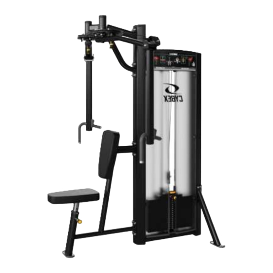
Pectoral fly / rear deltoid
Hide thumbs
Also See for Ion Series:
- Assembly instructions manual (38 pages) ,
- Assembly instructions manual (36 pages) ,
- Assembly instructions manual (40 pages)

Related Manuals for CYBEX Ion Series


Summary of Contents for CYBEX Ion Series
- Page 1 Ion Series Pectoral Fly / Rear Deltoid Assembly Instructions CI-FLY Part Number 1017135-0001 AA...
- Page 3 Corporate Headquarters Columbia Centre III, 9525 Bryn Mawr Avenue, Rosemont, Illinois 60018 • U.S.A. 847.288.3300 • FAX: 847.288.3703 Service phone number: 800.351.3737 (toll-free within U.S.A., Canada) Global Website: www.lifefitness.com International Offices AMERICAS United Kingdom All Other EMEA Countries and Distributor Business EMEA* North America Life Fitness UK LTD...
- Page 4 User and Service Documents Link https://lifefitness9512.zendesk.com/hc/en-us https://www.lftechsupport.com/web/document-library/documents Additional information is available online using the links above. أ علاه إل ر إبط باستخدإم إ لإ ن تر نت على إضافية معلومات تتوفر 点击上面的链接可在线获取更多信息。 Flere oplysninger er tilgængelige online gennem linket ovenfor. Bijkomende informatie is online beschikbaar via bovenstaande link.
-
Page 5: Table Of Contents
© Copyright 2021, Life Fitness, LLC. All Rights Reserved. Life Fitness, Hammer Strength, Cybex, ICG and SCIFIT are registered trademarks of Life Fitness, LLC and its affiliated companies and subsidiaries. Brunswick and related trademarks used under license from Brunswick Corporation. Disclaimer: Images and specifications are current as of the date of publication and are subject to change. -
Page 6: Safety Information
Safety Safety Information It is the sole responsibility of the purchaser of Life Fitness Family of Brands products to read the owner’s manual and warning labels and instruct all individuals, whether they are the end user or supervising personnel, on proper usage of the equipment. UNDERSTANDING EACH AND EVERY WARNING TO THE FULLEST IS IMPORTANT. -
Page 7: Product Labels
• Before use, examine all accessories approved for use with the Life Fitness Family of Brands equipment for damage or wear. Selectorized • Use only weight selector pins supplied by seller on weight stacks. Substitutes are forbidden. • Fully insert weight selector pins. Partial insertion can cause weights to fall unexpectedly. •... -
Page 8: Label Locations
Label Locations Item Description Qty. Multilingual Label with General Warning Serial Number Page 6 of 34... -
Page 9: Assembly
Assembly Component and Hardware List Tower Components Item Description Qty. Tower Frame Guide Rod Increment Weight Guide Rod Rear Shroud Weight Stack Label Tube Cap Top Cap Tower Hardware Kit Item Description Qty. Tower Hardware Kit, CI-FLY Hole Plug, 8.7 mm Shroud Retainer Grommet Screw, 8 x ¾", Phillips... - Page 10 Tower Hardware Kit Front Shroud Kit Components Item Description Qty. Front Shroud, Left Front Shroud, Right Bottom Cap Front Shroud Kit Hardware Kit Item Description Qty. Front Shroud Hardware Kit Screw, M4.2 x 0.7, Phillips Screw, M10 x 1.5, 20mm Washer, Flat 3/8"...
- Page 11 Components Item Description Qty. Support Leg, Front Support Leg, Rear Seat Frame Assembly Seat Post Assembly Overhead Frame Assembly Head Plate Pulley Bracket Front Cap Head Plate Assembly Increment Weight Assembly Multilingual Label Sheet Upper Work Arm Assembly, Left Upper Work Arm Assembly, Right Cam Assembly, Left Cam Assembly, Right Cable...
-
Page 12: Tools Required
Item Description Qty. Cotter Pin Cable Retainer Increment Weight Cap, LBS Increment Weight Cap, KG Hole Plug, 1" Spacer, Internal .653 Cable Retainer Cover Plate Pivot Shaft Threaded Cap Pulley, 3.5" OD Hardware Kit Tools Required • 7/16" Wrench • 10 mm Wrench •... -
Page 13: Assembly Procedure
Assembly Procedure Assemble Frame Components 1. Install screws and washers securing the front support leg to the tower frame using an 8 mm Allen wrench. Item Description Qty. Support Leg, Front Washer, Flat 3/8" Screw, M10 x 1.5, 25 mm Tighten hardware to 20-25 ft-lb (27.1-33.9 Nm). - Page 14 5. Install screws securing seat glide bushing to main frame using a Phillips screwdriver. Item Description Qty. Seat Post Assembly Seat Glide Bushing Seat Frame Screw, M5 x 10, Phillips Tighten hardware to 30-39 in-lb (3.4-4.4 Nm). 6. Install screws and washers securing the overhead frame assembly to the tower frame using an 8mm Allen wrench. Item Description Qty.
- Page 15 Assemble Tower 1. Install the increment weight bumper to the bottom plate of the tower frame. Item Description Qty. Increment Weight Bumper Tower Frame 2. Slide increment weight guide rods through the top of the tower frame and down through the clips in the increment weight. Place increment weight guide rods into holes at the bottom plate of the tower frame.
- Page 16 3. Thread increment weight guide rods into the bottom plate of the tower frame. Tighten using a crescent wrench. Item Description Qty. Increment Weight Guide Rod 4. Install nuts and washers securing the increment weight guide rods to the top plate of the tower frame using a 7/16" wrench. Item Description Qty.
- Page 17 7. Install screws and washers securing the bottom cap to the bottom of the tower frame using an 8mm Allen wrench. Item Description Qty. Bottom Cap Screw, M10 x 1.5, 20mm Washer, Flat 3/8" Tighten hardware to 8-10 ft-lb (10.8-13.5 Nm). 8.
- Page 18 10. Place guide rods with weight stack cushions into the holes at the bottom of the tower frame. Item Description Qty. Guide Rod Weight Stack Cushion 11. Lean guide rods outwards and slide weight stack down guide rods onto weight stack cushions. Slide head plate assembly down guide rods and onto weight stack.
- Page 19 13. Select the LBS (7.5) or KG (3.75) option of the increment weight cap. Press increment weight cap into the head plate assembly. Item Description Qty. Increment Weight Cap Head Plate Assembly 14. Thread head plate pulley bracket through the jam nut and into the head plate bayonet. See Cable Handling Guide for details.
- Page 20 15. Select either the LBS or KG weight stack label. Remove backing from label and apply to weight stack. NOTE: One weight stack label sheet, LBS or KG, is used for both weight stacks. Item Description Qty. Weight Stack Label Weight Stack 16.
- Page 21 20. Select the appropriate language from the multilingual label sheet. Remove backing from multilingual label and apply to the left and right slots in the front cap. Item Description Qty. Multilingual Label with General Warning Front Cap Install Work Arms 1.
- Page 22 4. Place threaded cap onto the shaft of the left upper work arm assembly. 5. Repeat Steps 1-4 to install the right upper work arm assembly 6. Route one end of the cable into the right cam assembly. 7. Install cable retainer securing the cable to the right cam assembly. 8.
- Page 23 9. Route cable from the right cam assembly through the pulley weldment on the rear side of the tower frame and down over the pulley located below the top cap. Route cable back up over the pulley located below the top cap on the front side of the tower frame and through the pulley weldment to the left cam assembly.
- Page 24 12. Install screws, washers, and locknuts securing the cable retainer cover plate to left cam assembly using an 8mm Allen wrench and a 17mm wrench. Item Description Qty. Cable Cam Assembly, Left Cable Retainer Cable Retainer Cover Plate Screw, M10 x 1.5, 50mm Washer, Flat 3/8"...
- Page 25 15. Install screws, washers, and pivot shaft securing the left lower work arm assembly to the left upper work arm assembly using a 7mm Allen wrench. Item Description Qty. Lower Work Arm Assembly, Left Upper Work Arm Assembly, Left Pivot Shaft Washer, .375"...
- Page 26 Install Seat and Back Pads 1. Install screws and washers securing the seat pad to the seat frame assembly using an 8mm Allen wrench. Item Description Qty. Seat Pad Washer, Flat 3/8" Screw, M10 x 1.5, 30mm Tighten hardware to 40-50 in-lb (4.5-5.6 Nm). 2.
-
Page 27: Product Information
Product Information Specifications Machine Weight: 543 lbs. 246 kg. Size (L x W x H): in. = 61 x 75 x 81 cm = 155 x 191 x 206 Live Area (L x W x H): in. = 97 x 99 x 93 cm = 246 x 251 x 236 Max User Weight: 300 lbs. -
Page 28: Cable Handling Guide
WARNING: Use of non certified “techs” note: Service warranties may be void if a non-Cybex-certified technician performs service work. Replacement of any strength cables should be performed by a Cybex certified technician. -
Page 29: Tensioning Cable
Tensioning Cable Cable should have enough tension so it stays seated into the pulley but not so tight that it pulls the head plate off the weight plate below it. 1. If the head plate has lifted, loosen the jam nuts at the terminations and loosen the threaded plugs a half turn until the head plate comes to rest on the weight plate below. -
Page 30: Strength Cable Wear Guide
Strength Cable Wear Guide Replace cable at first sign of any of the following: FRACTURES: Casing can crack or fracture under strains during use. Any crack in the casing merits cable replacement even if no wire rope is exposed. Be especially observant for fractures near the components on the cable assembly - IE. -
Page 31: Bolt To Floor Guide
Competitor Product The bolt down guidelines and procedures for Cybex products were determined by the company’s Engineering and Installation Development groups. These guidelines include which anchors to use and positioning of the anchors are required for Cybex product. • Cybex does not have that level of specification or engineering input for competitive product. -
Page 32: Anchor Types
3000psi (20 N/mm2) anchor length Pullout Force Cybex specifies Hilti ™ static and dynamic anchors. According to the anchor manufacturer, the recommended design pullout force (in tension) for the specified anchors, when properly installed in cracked concrete, is provided in the side table. This table should be used for reference only;... -
Page 33: Static Anchor Procedure
Static Anchor Procedure CAUTION: If it is possible that the length of your bolt will not provide the minimum requirement of 2.5” (63.5mm) of engagement, a longer anchor should be used. 1. Place unit into position to be mounted and cycle unit to set stance. 2. -
Page 34: Foot Dimensions
Foot Dimensions Use below image to determine foot specifications. Page 32 of 34... - Page 36 Columbia Center III - 9525 Bryn Mawr Ave, Rosemont, IL 60018 • 800-351-3737 • 847-288-3700 • FAX 800-216-8893 www.cybexintl.com...