Graco Therm-O-Flow 20 Instructions - Parts Manual
Hide thumbs
Also See for Therm-O-Flow 20:
- Instructions - parts manual (110 pages) ,
- Instructions-parts list manual (18 pages) ,
- Instructions - parts manual (78 pages)
Table of Contents
Advertisement
Quick Links
Instructions-Parts
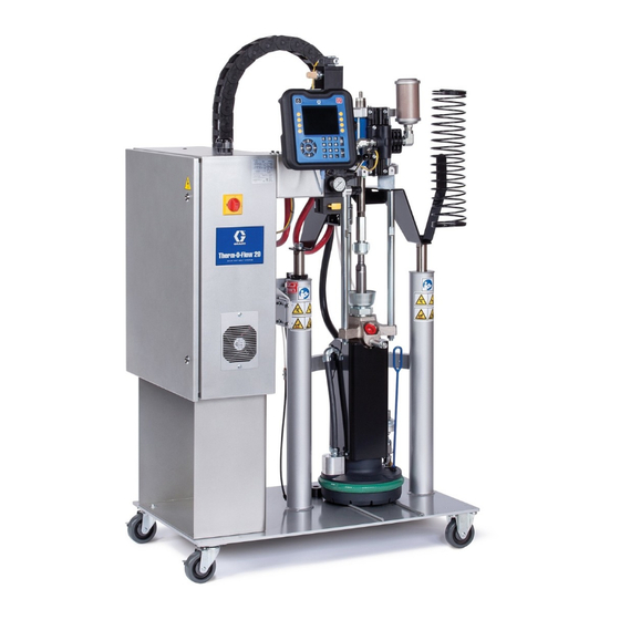
Therm-O-Flow
For applying hot melt sealant and adhesive materials from 20 Liter (5 Gallon) pails. For
professional use only.
Not approved for use in European explosive atmosphere locations.
Important Safety Instructions
Read all warnings and instructions in this manual
and in related manuals. Save these instructions.
Maximum Operating Temperature 400°F (204°C)
See page 7 for model information.
See Technical Specifications, page 110, for maximum
working pressures.
®
20
334129S
3143485
Certified to
CSA STD C22.2 No. 88
Conforms to
UL STD 499
EN
Advertisement
Table of Contents
Troubleshooting

Related Manuals for Graco Therm-O-Flow 20


Summary of Contents for Graco Therm-O-Flow 20
- Page 1 Instructions-Parts ® Therm-O-Flow 334129S For applying hot melt sealant and adhesive materials from 20 Liter (5 Gallon) pails. For professional use only. Not approved for use in European explosive atmosphere locations. Important Safety Instructions Read all warnings and instructions in this manual and in related manuals.
-
Page 2: Table Of Contents
Check Heater Resistance ....22 Therm-O-Flow 20 Supply Unit ....67 Select ADM Settings . -
Page 3: Related Manuals
Technical Specifications ....110 Graco Standard Warranty ....112... -
Page 4: Warnings
Warnings Warnings The following warnings are for the setup, use, grounding, maintenance, and repair of this equipment. The exclamation point symbol alerts you to a general warning and the hazard symbols refer to procedure-specific risks. When these symbols appear in the body of this manual or on warning labels, refer back to these Warnings. Product-specific hazard symbols and warnings not covered in this section may appear throughout the body of this manual where applicable. - Page 5 Warnings WARNING THERMAL EXPANSION HAZARD Fluids subjected to heat in confined spaces, including hoses, can create a rapid rise in pressure due to the thermal expansion. Over-pressurization can result in equipment rupture and serious injury. • Open a valve to relieve the fluid expansion during heating. •...
- Page 6 Warnings WARNING EQUIPMENT MISUSE HAZARD Misuse can cause death or serious injury. • Do not operate the unit when fatigued or under the influence of drugs or alcohol. • Do not exceed the maximum working pressure or temperature rating of the lowest rated system component.
-
Page 7: Models
Models Models The model number stamped on your system defines the equipment in the following categories. See Technical Specifications, page 110, for maximum working pressure. Zone Pump Platen Series Frame Size Air/Electric Config Ratio Style Code A Frame Size Code D Pump Ratio 5 Gallon (20 Liter) 23:1 CF (Carbon-Filled) -
Page 8: Component Identification
Component Identification Component Identification ti24594a . 1: TOF 20 Key: Lift Strap Positions Main Power Switch (can be locked in the open position) Multi-Zone Low Power Temperature Control Module (MZLP) Air Motor Solenoid Light Tower Electrical Power Input Cable Track Air Motor Ram Plate Bleed Stick Heated Pump... -
Page 9: Integrated Air Controls
Component Identification Integrated Air Controls . 2: Integrated Air Controls Key: CA Main Air Slider Valve CH Blowoff Pressure Gauge Turns air on and off to the entire system. When closed, Displays the blowoff pressure. the valve relieves pressure downstream. Can be locked in CJ Blowoff Air Regulator the closed position. -
Page 10: Electrical Control Enclosure
Component Identification Electrical Control Enclosure Back Panel With Transformer . 3: Electrical Enclosure Key: DA Multi-Zone Low Power Temperature Control Module DG Platen SSR (65A) (MZLP) DH Platen Contractor DB Ventilation Grill DJ Platen Fuse DC Electrical Control Panel DK Transformer Circuit Breaker DD Automatic Wiring Board (AWB) DL Transformer Fuse DE Power Supply (24V) -
Page 11: Advanced Display Module (Adm)
Component Identification Advanced Display Module (ADM) NOTICE The ADM display shows graphical and text information To prevent damage to the softkey buttons, do not related to setup and spray operations. For details on the press buttons with sharp objects such as pens, display and individual screens, see Appendix A - ADM, plastic cards, or fingernails. - Page 12 Component Identification . 5: Back View Part Number and Identification Label USB Interface CAN Cable Connection (Power Supply and Communication) Module Status LEDs Light Tower (Optional) Software Token Access Panel Table 1 ADM LED Status Descriptions Conditions Description System Status Green Solid Run Mode, System On Green Flashing...
-
Page 13: Screen Components
Component Identification Screen Components 1. Screen Order 2. Current date and time 3. Operating Mode 4. Faults, Status 5. MZLP Plug Identifier 6. Zone Setpoint Temperature 7. Zone Actual Temperature Operating Mode Description Component Status System Off The system does not have power. •... -
Page 14: Overview
Heated Pump and heated fluid moves to the application tool. Air and Fluid Hoses The Therm-O-Flow requires Graco single-circuit material hoses rated at a maximum of 1250 watts. Make sure all air and fluid hoses are properly sized for the system. -
Page 15: Setup
Setup Setup 1. Unpack the Ram 4. Make sure there is easy access to an appropriate electrical power source. The National Electrical 2. Locate and Install the Ram Code requires 3 ft (0.9 m) of open space in front of the electrical panel. -
Page 16: Mechanical Setup
4. Ensure Drum Low and Empty Sensors (C) are mounted as shown. 1. Fill displacement Pump wet cup 2/3 full with Graco NOTE: The Drum Low and Empty Sensors are used to Throat Seal Liquid (TSL™) for Butyl and PSA indicate that a drum is empty. -
Page 17: Install Heated Hose
Setup Install Heated Hose 4. Repeat for any remaining channels. 5. Install cap on any unused MZLP electrical To connect a hose to a fluid control device or heated connectors. manifold. Connect the small 8 pin connector from the heated 1. -
Page 18: Connect Multiple Devices
Setup Connect Multiple Devices • Connect fluid control devices to a heated hose or the electrical enclosure. Use accessories if necessary. If your application requires multiple fluid control devices: • Setup all heat zones on Heat-A and Heat-B screens. • Connect heated hose electrical connections to the electrical enclosure. -
Page 19: Connect Power
Setup Connect Power The Electrical Control Panel comes already attached and wired to the Ram, however before the supply unit becomes functional you must connect the Electrical Control Panel to a power source. All electrical wiring must be done by a qualified electrician and comply with all local codes and . -
Page 20: Grounding
Setup Grounding Material drums: follow local code. Use only metal drums placed on a grounded surface. Do not place the drum on a nonconductive surface, such as paper or Ground the unit as instructed here and in the cardboard, which interrupts the grounding continuity component manuals. -
Page 21: Check Sensor Resistance
Setup Check Sensor Resistance Table 3 RTD Sensors RTD Range MZLP MZLP Plug Component (Ohms) Ram Plate 100 +/- 2 Fluid Pump 100 +/- 2 To reduce risk of injury or damage to equipment, Heated conduct these electrical checks with the Main Power 100 +/- 2 Accessory 1 Switch OFF. -
Page 22: Check Heater Resistance
Setup Check Heater Resistance 2. Make electrical resistance checks for the components. 3. Replace any parts whose resistance readings do not comply with the ranges listed in tables. To reduce risk of injury or damage to equipment, NOTE: Check resistance at ambient room temperature conduct these electrical checks with the Main Power 63°-77°F (17°-25°C). -
Page 23: Select Adm Settings
Setup Select ADM Settings 4. Set alarm levels on the System 2 screen. NOTE: See Appendix A - ADM, page 96 for detailed ADM information, including general operation. 1. Turn Main Power Switch ON. 2. When the ADM is finished starting up, press to switch from the Operation screens to the Setup screens. - Page 24 Setup 6. If a secondary system is used, set temperatures on 9. To setup the optional Schedule function, see the Heat-B-screens. Schedule, page 36. The schedule function allows the system to automatically enable and disable 7. Set the system date and time on the Advanced 1 heating and setback at specified times.
-
Page 25: Connect Plc (Hard Wired Interface Version)
Setup Connect PLC (Hard Wired Table 7 Output Error States Interface Version) Error State Error State Bit Bit High Machine is good, no errors are present Active Unit Drum A PLC can control and monitor all items shown in the Customer Digital Inputs and Outputs shown on the Active Unit Drum Diagnostics screen. - Page 26 Setup NOTE: Each connector has four signals. The MZLP board specifies the input range for each signal. See the following table for pin assignments. . 16 H1 Customer Input Signal H2 Customer Output Signal Inputs: High: 10–30 VDC, Low: 0–5 VDC. Inputs function without concern for polarity.
- Page 27 Setup PLC Connections Block Diagrams The following block diagrams show how to connect customer inputs and outputs to the MZLP. For convenience, each system ships with connector kit 24P176. If a connector is lost or damaged, order kit 24P176 for replacements. .
-
Page 28: Operation
Operation Operation 1. Turn the Main Power Switch ON. The Graco logo NOTICE will display until communication and initialization is complete. Use fluids that are chemically compatible with the equipment wetted parts. See Technical Specifications in all of the equipment manuals. -
Page 29: Load Material
Operation Load Material 4. Fill displacement Pump wet cup 2/3 full with Graco Throat Seal Liquid (TSL™) for Butyl and PSA materials. NOTICE To prevent damage to Platen wipers, do not use a pail ® NOTE: Use IsoGuard Select (IGS) (part no. 24F516) of material that has been dented or damaged. -
Page 30: Heat Up System
Operation Heat Up System 7. Remove the Ram Plate Bleed Stick (R). To reduce the risk of bursting a hose, never pressurize a hot melt system before turning on the heat. The air will be locked from the Air Motor until all temperature zones are within a preset window of the temperature setpoints. -
Page 31: Prime Pump
Operation Prime Pump 3. Adjust the Air Motor Slider Valve (CM) to the open position. 1. Ensure that the system has completed the heat soak cycle. The display status bar should read Active. 2. Adjust the Air Motor Air Regulator (CK) to 0 psi. 4. - Page 32 Operation For Tandem Operation 6. If a new pail was installed and the unit is equipped with proximity sensors, press the Pump Ready Complete steps 1-5 on page 31 for the inactive unit. Note that the heat will remain on for the inactive unit button .
-
Page 33: Prime System
Operation Prime System 7. Close the Main Air Slider Valve (CA) and release the trigger lock. 8. Engage the trigger lock. 1. Close the Main Air Slider Valve (CA). 2. If using a manual gun, lock the dispense valve . 24: Trigger Lock Engaged trigger open by pulling and securing the trigger using the trigger retainer (Z). -
Page 34: Pressure Relief Procedure
Operation Pressure Relief Procedure 3. Set the Ram Director Valve (CC) to the neutral position. Follow the Pressure Relief Procedure Whenever you see this symbol. This equipment stays pressurized until pressure is manually relieved. To help prevent serious injury from pressurized fluid, such as skin injection, splashing fluid and moving parts, follow the Pressure Relief Procedure when you stop spraying and before cleaning, checking, or servicing... -
Page 35: Stop Controls
Operation Stop Controls NOTE: If work needs to be performed on the Ram portion, perform the following additional steps to relieve any trapped air in the inactive portion of the Ram. Normal Stop Control 9. Validate that the Heated Pump is fully supported To stop all electrical and most pneumatic processes, and is resting on the bottom plate. -
Page 36: Shutdown
Operation Shutdown 1. Press to disable the heaters and Pump. The screen will say “Inactive”. If using the Schedule function, the heaters and Pump will be disabled automatically at the set time. Only press disable the heating system before the set time. If the heaters were manually disabled, the Schedule function will automatically enable them at the next set time. -
Page 37: Change Pail
Operation Use the Schedule Function Table 9 Schedule Screen Color Identification Color Description At the end of the work day leave the Main Power Switch ON. The Schedule function will automatically enable Green System on and disable the heaters and Pump at the specified Yellow Setback times. - Page 38 Operation 2. Push in the Air Motor Slider Valve (CM) to stop the 6. Inspect Platen and if necessary, remove any Pump. remaining material or material build-up. 7. Follow steps in Load Material, page 29, and Prime Pump, page 31. 3.
-
Page 39: Troubleshooting
Troubleshooting Troubleshooting Light Tower (Optional) Signal Description Red Light Off If green light is also off, system power may be off or system operating mode is Inactive. If green is on or flashing, there are no active errors Red Light On User interaction required —... -
Page 40: Error Codes
Troubleshooting Error Codes The last digit of the error code indicates which system component the error applies. The “#” (pound) character indicates the code applies to multiple system There are three types of errors that can occur. Errors are indicated on the display as well as by the optional components. - Page 41 Troubleshooting Code Description Type Cause Solution A3MF AWB Clean Fan Filter Alarm Cooling inlet Clean inlet screen. screen is dirty A4 _ High Current Unit _ Alarm Defective or Verify accessory is rated for 240 VAC. Zone _ shorted to Verify heater resistance and check for shorts to ground on ground.
- Page 42 Troubleshooting Code Description Type Cause Solution CCAG Comm. Error, Alarm CGM Module Power removed from Gateway. Restore power. Gateway is no longer Rotary switch on Gateway changed to responding positions between 2 and 8 (must be in 0, 1, or >8 positions).
- Page 43 Troubleshooting Code Description Type Cause Solution DC X Pump Diving Alarm Pump is trying Adjust the drum empty level sensor to detect to feed an empty state. adhesive, no Ensure the Ram Director Valve is in the down adhesive to position and sufficient air is forcing the Ram feed.
- Page 44 Troubleshooting Code Description Type Cause Solution T3 _ High Temp. Unit _ Deviation Temperature Change High Temp Deviation Offset. Zone _ reading has Verify setpoint upstream is not hotter than this risen too high zone’s setpoint. T4C# AWB Temperature Alarm Cooling fan Ensure inlet and outlets are not obstructed.
- Page 45 Troubleshooting Code Description Type Cause Solution V8M# No Line Voltage Alarm Incoming line Verify Transformer has the correct tap MZLP _ voltage is less selected. than 100 VAC. Verify CB-1 or FU-4, FU-5, and FU-6 are not tripped/blown. Verify RCD-1 is not tripped. Measure incoming power with system unplugged.
-
Page 46: Ram Troubleshooting
Troubleshooting Ram Troubleshooting Problem Cause Solution Ram will not raise or lower. Closed main air valve or clogged air Open air valve; clear air line. line, Not enough Ram air pressure. Increase Ram air pressure. Worn or damaged Ram piston. Replace piston. -
Page 47: Heated Pump Troubleshooting
Troubleshooting Heated Pump Troubleshooting See Pump manual for additional Pump troubleshooting information. See Component Identification, page 8. Problem Cause Solution Rapid downstroke or upstroke (Pump Material not heated to proper Check and adjust temperature to cavitation). temperature. proper setpoint. Wait for Pump/Platen to heat up. -
Page 48: Repair
Repair Repair Replace Wipers 1. To replace a worn or damaged wiper raise the Ram plate up out of the drum. Perform steps 1 through 7 of Change Pail, page 37. 2. Separate the wiper joint, and bend back the strapping that covers the clamp (207). -
Page 49: Replace Platen Rtd
Repair Replace Platen RTD 4. Remove the front and right side Pump cover. Reference Electrical Schematics, page 61, for wiring connections. 1. If the material pail has already been removed from the supply unit, go to step 2. If you need to remove the material pail, see Change Pail, page 37. -
Page 50: Separate The Air Motor And Pump
Repair Separate the Air Motor and 8. If the system includes a Pump shield, remove the Pump sheet metal enclosure (A). See F . 29. Pump a. Remove the cover screws (B). b. Remove the heater bands (HB) and disconnect the ground wire (R). - Page 51 Repair . 29 334129S...
-
Page 52: Remove Platen
Repair Remove Platen 8. Remove the white ceramic caps and disconnect the electrical wires from the heater band (309a, 309b). 9. Remove the screw that holds the heater band in place. 1. Turn the Main Power Switch OFF. 10. Remove the heater band (309a, 309b) from the Pump. -
Page 53: Replace Mzlp Fuse
Repair 2. Remove the screws that hold the front shroud in NOTICE place and remove the front shroud. To prevent system damage, always use fast acting 3. If the sensor wire is connected to the electrical fuses. Fast acting fuses are required for enclosure, disconnect it. -
Page 54: Replace Mzlp
Repair Replace MZLP 6. To reassemble the MZLP, set the MZLP rotary switch based on location. See Table 10 MZLP Rotary Switch. 7. Use the four screws (115) to install the MZLP (111 or 112) to the electrical enclosure. 1. Turn the Main Power Switch OFF. 8. -
Page 55: Replace Mzlp Daughter Card
Repair Replace MZLP Daughter Card 5. Plug the new daughter card (112a) into the MZLP (112). 6. Use the screws (112b) to secure the daughter card to the MZLP (112). 7. Connect the cables to the new daughter card 1. Turn the Main Power Switch OFF. (112a). -
Page 56: Replace Awb
Repair Replace AWB Replace Power Supply 1. Turn the Main Power Switch OFF. 2. Note the location of each cable, then unplug all cables from the AWB (205). NOTE: For an AWB on a secondary system, remove the connector (182) and connect to the new AWB. 1. -
Page 57: Replace Fan
Repair Replace Fan 6. Remove the screws (141), grill (137), four nuts (139), rear fan grill (138), and fan (136). 1. Turn the Main Power Switch OFF. 2. Disconnect the plug from the power outlet or turn off the Circuit Breaker for incoming power. 3. -
Page 58: Replace Transformer
Repair Replace Transformer 13. Connect the Transformer output power harness (234) to the power terminal connections. Torque to 25–27 in-lbs (2.8–3.1 N•m). Table 11 Transformer Output Power Harness Connections See F . 35, page 59. Power Harness Wires CR-2 Connections 1. - Page 59 Repair CR-2 . 35: Inside of Electrical Control Enclosure 334129S...
-
Page 60: Update Software
Repair Update Software NOTE: When the screen turns on, you will see the following screens: When software is updated on the ADM, the software is then automatically updated on all connected GCA First: components. A status screen is shown while software Software is checking is updating to indicate progress. -
Page 61: Electrical Schematics
Electrical Schematics Electrical Schematics 230V, 3 Phase/60Hz 334129S... -
Page 62: 400V, 3 Phase/50Hz
Electrical Schematics 400V, 3 Phase/50Hz 334129S... -
Page 63: 400-600Vv, 3 Phase/60Hz
Electrical Schematics 400-600VV, 3 Phase/60Hz 334129S... -
Page 64: Awb And Mzlp#1
Electrical Schematics AWB and MZLP#1 334129S... -
Page 65: Mzlp#2, Mzlp#3, Overtemp, And Pump Heaters
Electrical Schematics MZLP#2, MZLP#3, Overtemp, and Pump Heaters 334129S... -
Page 66: Mzlp Zones
Electrical Schematics MZLP Zones TYPICAL ZONE PIN OUT MZTCM-1 CONNECTOR PIN # FUNCTION MZTCM-1 ZONE 1,L2 SHIELD ZONE 2,L1 ZONE 2,L2 JUMPER ZONE 1,START MZTCM-1 J9 ZONE 1,RTD JUMPER ZONE 1,L1 RTD EXCITE ZONE 2,START ZONE 2,RTD ZONE 3,L2 TYPICAL ZONE PIN OUT SHIELD ZONE 4,L1 ZONE 4,L2... -
Page 67: Parts
Parts Parts Therm-O-Flow 20 Supply Unit 21 12 ti25320a 334129S... -
Page 68: Therm-O-Flow 20 Supply Unit
Parts Therm-O-Flow 20 Supply Unit Part Description Part Description 288543 BRACKET, hose, spring Frame BRACKET, enclosure, ram 24W870 KIT, air control; see Air Control Assembly, page 69 112166 SCREW, cap, sch CONTROL, electrical (not used 110755 WASHER, plain with air control only systems) 100016 WASHER, lock MODULE, pump;... -
Page 69: Air Control Assembly
Parts Air Control Assembly ti25005b ti25025b Part Description Part Description 24W870 KIT, CONTROL, air, 3 regulator; 17A557 HARNESS, solenoid, MZLP see manual 334201 113445 FITTING, elbow, street 121235 SOLENOID, air motor, ram 121282 FITTING, swivel, straight 120375 ADAPTER, elbow, 3/4-14 nptf x 1/2-14 npsm 255651 KIT, reg, air motor, ram Replacement Warning Labels, signs, tabs, and cards... -
Page 70: Electrical Module
Parts Electrical Module 152 153 145 147 177, 119 101 113 ti25023c 334129S... - Page 71 Parts 128 127 334129S...
-
Page 72: Electrical Control Module Parts
Parts Electrical Control Module Parts Part Description Part Description ENCLOSURE, electrical HARNESS, pump, mzlp1, tb, tof BUSHING, strain relief, m40 HARNESS, output, mzlp1, ssr, thread contact NUT, strain relief, m40 thread 17A555 HARNESS, pump, reed switch, tof 1 125946 PLUG, hole, 1/2 in 17A559 HARNESS, board, mxm, comm 123967 KNOB, operator disconnect 127511 CABLE, board, samtec... - Page 73 Parts Part Description Part Description 121253 KNOB, display adj., ram pkgs HARNESS, input, mzlp1, RTD 127771 (Primary assemblies only) BRIDGE, plug-in, 2pos, ut16 BRACKET, pendant pivot, (400V and Transformer modules (Primary assemblies only) only) 101550 SCREW, cap, sch FERRULE, wire, 10awg (Primary assemblies only) (230V modules only;...
-
Page 74: Electrical Panel
Parts Electrical Panel 230V 400V Transformer 216, 229 1 230, 231 1 214 1 223, 224 215 1 210 1 202, 203, 204, 236 234 6 Transformer Panel Shown Torque terminals to 25-27 in-lbs (2.8-3.1 N•m). Torque terminals to 13.3-16 in-lbs (1.5-1.8 N•m) Torque terminals to 4.53-6.2 in-lbs (0.5-0.7 N•m) 334129S... - Page 75 Parts 230V Panel 400V Panel Torque terminals to 25-27 in-lbs (2.8-3.1 N•m). Torque terminals to 13.3-16 in-lbs (1.5-1.8 N•m) Torque terminals to 4.53-6.2 in-lbs (0.5-0.7 N•m) 334129S...
-
Page 76: Electrical Panel Parts
Parts Electrical Panel Parts Part Description Part Description 127744 CIRCUIT, breaker, 3p, 32a, ul489; PANEL, elec, tof, 11ga, zinc 117666 TERMINAL, ground 230V Panel only 113783 SCREW, machine, pn hd 127745 CIRCUIT, breaker, 20a, 100985 WASHER, lock ext 4p, ul489; 400V Panel only 24V816 MODULE, gca, awb See Code C Table RAIL, din, 6.5in... -
Page 77: Merkur 2200, 23:1 Pump Modules
Parts Merkur 2200, 23:1 Pump Modules 309a 309b ti25311a Torque to 50-60 ft-lbs (68-81 N•m). Coat inside of heater (309a, 309b) only to within 3/4 in. of vertical ends with non-silicone heat sink compound before Torque to 145-155 ft-lbs (196-210 N•m). mounting. -
Page 78: Merkur 2200, 23:1 Pump Modules
Parts Merkur 2200, 23:1 Pump Modules Part Description 24W754 MOTOR, air, 6 in, 4.75 stroke, blue 1 C20485 FITTING, hex, nipple 24R885 SWITCH, reed assy BRACKET, motor mount 15H397 ADAPTER, rod, pump 16A223 ROD, tie, vert driver 106166 NUT, mach ,hex HEATER, pump, 600 watt 24W152 PUMP, tof200, cf;... -
Page 79: Merkur 3400, 36:1 Pump Modules
Parts Merkur 3400, 36:1 Pump Modules 309a 5 336a 320 4 311 6 7 8 322 3 321 4 5 336b 309b 5 316 2 ti25312a Torque to 50-60 ft-lbs (68-81 N•m). Coat inside of heater (309a, 309b) only to within 3/4 in. of vertical ends with non-silicone heat sink compound before mounting. -
Page 80: Merkur 3400, 36:1 Pump Modules
Parts Merkur 3400, 36:1 Pump Modules Part Description 24R015 MOTOR, assy, air, 7.5 in, blue C20485 FITTING, nipple, hex 24R885 SWITCH, reed assy BRACKET, motor mount, tof 200 15H397 ADAPTER, rod, pump 16A223 ROD, tie, vert driver 106166 NUT, mach, hex HEATER, pump, 600 watt 24W152 PUMP, tof20, long shaft, cf;... -
Page 81: Nxt 6500, 70:1 Pump Modules
Parts NXT 6500, 70:1 Pump Modules 407a 430a 430b 407b Torque to 50-60 ft-lbs (68-81 Coat inside of heater (407a, 407b) only to within 3/4 in. of N•m). vertical ends with non-silicone heat sink compound before mounting. Torque to 145-155 ft-lbs (196-210 N•m). Torque to 150 ft-lbs (203 N•m). -
Page 82: Nxt 6500, 70:1 Pump Modules
Parts NXT 6500, 70:1 Pump Modules Part Description N65LR0 MOTOR, 6500, low-noise, remote 1 120375 ADAPTER, elbow, 3/4 NPTI x 1/2 NPTE 15J288 BRACKET, mounting, motor, tof20 2 17A406 ADAPTER, rod, pump, tof 16A223 ROD, tie, vert driver 106166 NUT, mach, hex 128322 HEATER, pump, 600 watt 24W152 PUMP, tof20, cf;... -
Page 83: Pump Shield
Parts Pump Shield Part Description COVER, pump, bottom COVER, pump, back COVER, pump, front C20474 SCREW, self-tapping 17J504 LABEL, warning 104088 RIVET, blind 15J075 LABEL, safety, hot surface and shock Replacement Warning labels, signs, tags, and cards are available at no cost. 334129S... -
Page 84: President, 15:1 Pump Module
Parts President, 15:1 Pump Module 551a 551h 551d 551r 551n 551r 551b 551s 551m 551c 551p 551g 551f 551e 551k 551j tii000a Torque to 20-30 ft-lbs (27-41 N•m). Torque to 30-40 ft-lbs (41-54 N•m). 334129S... - Page 85 Parts Part Description 288505 PUMP, president 551a 24B229 MOTOR, AIR, president 551b 918417 PUMP, hot melt mini-5 551c --- PLATE, president mounting 551d 198369 ROD, standoff 551e 100340 NUT 551f 100133 WASHER, lock, 3/8 551g 298073 ADAPTER, pump 551h 156082 PACKING, o-ring, 112 551j 112166 SCREW, cap, sch 551k 100016 WASHER, lock...
-
Page 86: Heated Platens
Parts Heated Platens 24V742, Heated Drum Platen, Standard Finned Bottom (Code E-option F) 24V743, Heated Drum Platen, Smooth Bottom (Code E-option S) 613 630 631 ti25315c Coat RTD sensor (616) with non-silicone heat sink Coat bottom of overtemperature switch (627) with compound. - Page 87 Parts Part Description Part Description C38163 WASHER, lock, ext. tooth PLATEN - see table below C19049 SCREW, mach, slotted, md hd C31052 HOSE, seal, Mini - 5 15C171 GASKET 207440 VALVE, dispenser 102931 NUT, mach. hex 24X439 HANDLE, bleed WASHER, lock, internal tooth ADAPTER, bushing CONDUCTOR, heater 514930 SCREW, cap, skt hd...
-
Page 88: Accessories And Kits
Accessories and Kits Accessories and Kits Wiper Kits Part No. Description Part No. Description CGMEP0 EitherNet/IP C31065 Seal Kit CGMDN0 DeviceNet CGMPB0 ProfiBus Applicators and Dispense CGMPN0 ProfiNet Valves Flow Control and Manifolds Part No. Description Part No. Description 249515 Manual Gun, Top Feed, 240V 243700 Heated Air Operated Mastic Pressure... -
Page 89: Light Tower Kit, 24W589
Accessories and Kits Light Tower Kit, 24W589 Tie Rod Kits Use to retrofit Check-Mate 800 Displacement Pump to an existing Therm-O-Flow system. Part No. Description 24V750 Bulldog® and Senator® Tie Rod Kit; see manual 334131 24V754 NXT® Tie Rod Kit; see manual 334132 334129S... -
Page 90: Heated Hoses And Fittings
Accessories and Kits Heated Hoses and Fittings (9/16 in -18 (3/4 in -16 (7/8 in -14 (1-1/16 in -12 (1-5/16 in -12 (1-5/8 in -12 Hose Diameter JIC) JIC) JIC) JIC) JIC) JIC) Hose Length 3 ft (1.5 m) None None None 15C586... - Page 91 Accessories and Kits (9/16 in -18 (3/4 in -16 (7/8 in -14 (1-1/16 in -12 (1-5/16 in -12 (1-5/8 in -12 Hose Diameter JIC) JIC) JIC) JIC) JIC) JIC) Compact Heated 116766 16V432 116766 Regulator, 289208 121311 116765 116766 120267 Inlet &...
-
Page 92: Channel Upgrade Kit, 24V755
Accessories and Kits 8 Channel Upgrade Kit, 24V755 Use this kit to upgrade a 4 Channel system to an 8 channel system. Part Description Part Description MODULE, GCA, MZLP 16W035 CONNECTOR, jumper 125856 SCREW, 8–32, serrated flange 17A544 HARNESS, power, MZLP2, AWB 16T440 CAP, souriau, UTS14 112190 STRAP, wrist, grounding 127511 CABLE, board, samtec... -
Page 93: Zone Upgrade Kit Installation
Accessories and Kits 8 Zone Upgrade Kit Installation 1. Disconnect the plug from the power outlet or turn off the Circuit Breaker for incoming power. 2. Place the grounding wrist strap (7) over your wrist and secure the other end to a grounded surface. 3. -
Page 94: 12 Channel Upgrade Kit, 24V756
Accessories and Kits 12 Channel Upgrade Kit, 24V756 Use this kit to upgrade an 8 channel system to a 12 channel system. Part Description Part Description MODULE, GCA, MZLP 17A545 HARNESS, power, MZLP2/3, 125856 SCREW, 8–32, serrated flange 112190 STRAP, wrist, grounding 16T440 CAP, souriau, UTS14 17C712 TOKEN, software upgrade 127511 CABLE, board, samtec... -
Page 95: 12 Zone Upgrade Kit Installation
Accessories and Kits 12 Zone Upgrade Kit Installation 1. Disconnect the plug from the power outlet or turn off the Circuit Breaker for incoming power. 2. Place the grounding wrist strap (7) over your wrist and secure the other end to a grounded surface. 3. -
Page 96: Appendix A - Adm
Appendix A - ADM Appendix A - ADM General Operation Enable, Disable Heating System ADM Power To enable or disable the entire heating system, press . To set which channels are active when the The ADM automatically turns on when the Main Power heating system is enabled, use the Heat-A and Heat-B Switch is ON. -
Page 97: Icons
Appendix A - ADM Icons Screen Icons Softkey Icons These are frequently used icons on the screens. The The following icons appear in the ADM, directly to the following descriptions explain what each icon left or right of the soft key which activates that represents. -
Page 98: Operation Screens
Appendix A - ADM Operation Screens Color A and B Zone Status White Home Green On and at setpoint temperature This screen shows the temperature state of the system and material usage. Outside of alarm range Yellow Outside of advisory range Green/Yellow Flashing Warmup Events... - Page 99 Appendix A - ADM Errors CAN: 24 VDC power supply voltage reading (18-28 VDC) DI: System Digital Inputs 0: Drum Empty 1: Drum Low 2: Pump Cycle Switch Up 3: Pump Cycle Switch Down DO: System Digital Outputs 0: Pump Solenoid 1: Not Used 2: Not Used 3: Not Used...
-
Page 100: Setup Screens
Appendix A - ADM Setup Screens Enable Tandem System: Enable all secondary system ADM screens. NOTE: It is important to set all settings in the System Heat Soak: Time for to preheat after all zones have screens correctly to ensure optimal system reached their target temperatures. - Page 101 Appendix A - ADM Language: Language displayed on the screen. material set temperatures are less than 200° F (93° C), the Slow option may be best for the application. Date Format: Choose the format of the date. Advanced 3 Date: Set the date. Time: Set the time.
- Page 102 4. If more than one Therm-O-Flow .gti file is present in the “GRACO/SOFTWARE/” directory on the USB stick, select the correct file to transfer using the pull-down selection control.
- Page 103 Appendix A - ADM Heat - A Use these screens to set target and setback temperatures for the Pump, Platen, and zones. Select which system needs to use the heated accessory. Zone Types: • Hose • • • Flowmeter • Pressure Regulator •...
- Page 104 Appendix A - ADM Maintenance - A Gateway 1 and 2 If the Therm-O-Flow system has a communication gateway module (CGM) installed, an additional “Gateway” chapter containing 1 or 2 pages will be available in the setup screens. These pages enable the user to set the CGM IP or device address, configure the field bus protocol selections, and enable the user to view the mapping information programmed into the...
-
Page 105: Appendix B - Usb Data
Once full, the system will overwrite the When downloading from multiple ADMs, there will be oldest data. one sub-folder in the GRACO folder for each ADM. NOTE: To prevent losing any data, never go more than The log files should be opened in a spreadsheet 43 days without downloading the logs. -
Page 106: Usb Logs
NOTE: If the SETTINGS.TXT or DISPTEXT.TXT files These logs (5-BLACKB.CSV, 6-DIAGN.CSV) are remain in the UPLOAD folder, they will be uploaded designed to provide useful information to Graco when every time the USB drive is inserted into the calling for technical assistance. -
Page 107: System Language File
Appendix B - USB Data System Language File Create Custom Language Strings The system language file name is DISPTEXT.TXT and is stored in the DOWNLOAD folder. The custom language file is a tab-delimited text file that contains two columns. The first column consists of a A system language file automatically downloads each list of strings in the language selected at the time of time a USB flash drive is inserted. -
Page 108: Dimensions
Dimensions Dimensions Ram Mounting and Clearance in. (mm) in. (mm) in. (mm) in. (mm) in. (mm) in. (mm) in. (mm) in. (mm) in. (mm) in. (mm) in. (mm) in. (mm) 40.8 29.7 (1016) (1036) (1524) (1574) (711) (914) (558) (609) (754) (279) (152) - Page 109 Dimensions 15:1 in. (mm) in. (mm) in. (mm) in. (mm) in. (mm) in. (mm) in. (mm) in. (mm) in. (mm) in. (mm) 29.7 38.5 (1016) (1219) (977) (1574) (711) (558) (609) (754) (152) (25.4) Height (H) Dimensions Fully Raised 73.5 in (1866 mm) Fully Lowered 56.5 in (1435 mm) 334129S...
-
Page 110: Technical Specifications
Technical Specifications Technical Specifications Therm-O-Flow 20 Hot Melt System U.S. Metric Air inlet size 1/2 npsm(f) Air motor sound data See Air Motor instruction manual. Wetted Parts carbon steel, brass, chrome, zinc, nickel plating, stainless steel (304, 316, 440, and 17-4 PH), alloy steel, ductile iron, PTFE... - Page 111 Technical Specifications Therm-O-Flow 20 Hot Melt System Voltage (as selected) 220/240 V, 3-phase, 50/60 Hz 380/400 V, 3-phase, 50/60 Hz 470/490 V, 3-phase, 50/60 Hz 575 V, 3-phase, 50/60 Hz Peak Consumption (includes drum melt grid, pump, and a 6kVa transformer for the 230 V hoses and accessories) Standard melt grid platen with 6.4 kVa...
-
Page 112: Graco Standard Warranty
With the exception of any special, extended, or limited warranty published by Graco, Graco will, for a period of twelve months from the date of sale, repair or replace any part of the equipment determined by Graco to be defective.