Table of Contents
Advertisement
Quick Links
Operation
®
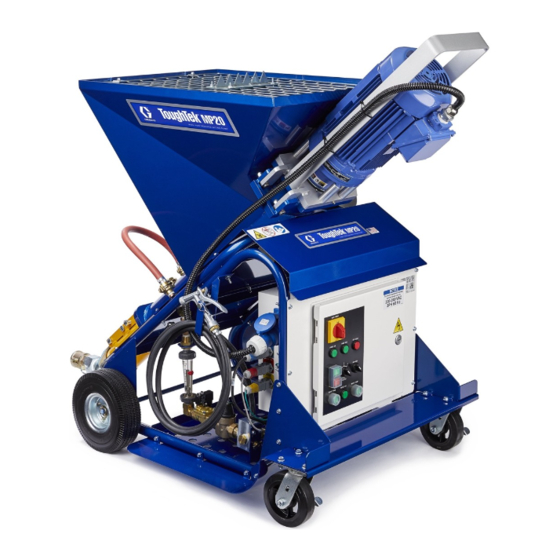
ToughTek
Electric mixing pump for water-based cementitious materials. For professional use only.
Not approved for use in explosive atmospheres or hazardous locations.
See Page 2 for model information.
Maximum Working Pressure: 300 psi (
Important Safety Instructions
Read all warnings and instructions in this and all
related manuals. Save these instructions.
MP-Series Mixing Pumps
2.07 MPa, 20.7 bar)
3A4349B
EN
Advertisement
Table of Contents

Related Manuals for Graco ToughTek MP-Series


Summary of Contents for Graco ToughTek MP-Series
- Page 1 Operation 3A4349B ® ToughTek MP-Series Mixing Pumps Electric mixing pump for water-based cementitious materials. For professional use only. Not approved for use in explosive atmospheres or hazardous locations. See Page 2 for model information. Maximum Working Pressure: 300 psi ( 2.07 MPa, 20.7 bar) Important Safety Instructions Read all warnings and instructions in this and all...
-
Page 2: Table Of Contents
Graco Standard Warranty ......48 Graco Information ......48... -
Page 3: Warnings
Warnings Warnings The following warnings are for the setup, use, grounding, maintenance, and repair of this equipment. The exclama- tion point symbol alerts you to a general warning and the hazard symbols refer to procedure-specific risks. When these symbols appear in the body of this manual or on warning labels, refer back to these Warnings. Product-specific hazard symbols and warnings not covered in this section may appear throughout the body of this manual where applicable. - Page 4 Warnings WARNING EQUIPMENT MISUSE HAZARD Misuse can cause death or serious injury. • Do not operate the unit when fatigued or under the influence of drugs or alcohol. • Do not exceed the maximum working pressure or temperature rating of the lowest rated system component.
-
Page 5: Component Identification
Component Identification Component Identification MP-20 and MP-40 Series Ref. Description Ref. Description Motor Latch Pressure Test Hose Pump Assembly Outlet Power Cable Clean-Out Shaft Motor Cable Water Pump Drive/Mix Shaft Water Pump Inlet Gear Box Motor Water Pump System Bypass Outlet Rotor/Stator Pump Water Flow Meter Control Box... -
Page 6: Control Box
Component Identification Control Box Ref. Description Power Out Connector Main Power In Connector Water Valve Connector Water Pressure Connector Remote Switch Connector Water Pump Connector Control Box Control Panel Ref. Description Main Power Disconnect Switch Start/Stop Push Button Speed Selector Knob Forward/Reverse Pump Direction Switch Water Prime Button Water Pump Button... -
Page 7: Water Pressure Over-Ride Plug (Op)
Component Identification Water Pressure Over-ride Plug (OP) The water solenoid valve requires 40 psi of water pressure to be energized. If the water pressure is not 40 psi or greater, the solenoid valve will remain normally closed, blocking the flow of water. This operation can be overridden by unplugging the water pressure connector (DD) and connecting the water pressure override plug (OP). -
Page 8: Set Up
Set Up Set Up 3. Make sure the motor shaft adapter (MS) and drive/mix shaft (D) are aligned so the drive shaft flat slides into the motor shaft adapter slot. If they do not align, rotate them into position. NOTE: For letter references, see the Component Identification section, starting on page 5. -
Page 9: Electrical Connections
Set Up 5. Secure the hopper grate (J) onto the top of the hop- Electrical Connections per (H). Power Cable Color Code Power Cable MTA727 To help prevent injury from moving parts, do not (for systems 25M060, 25M061): operate with the grate (J) removed. Line 1 Black Line 2... -
Page 10: Operation
Operation Operation NOTE: For letter references, see the Component 3. Place the applicator into a waste container. Identification section, starting on page 5. 4. Turn the main power disconnect switch (T) to ON. Priming with Water 5. Open the ball valve directly before the water pump system bypass outlet (Q). - Page 11 17. Reattach the hose to the pump outlet (L). The sys- NOTE: If water does not fill the mixing chamber, see tem is ready to prime with material. Startup After Extended Storage, page 18, or con- tact Graco Technical Support. 3A4349B...
-
Page 12: Pump Pressure Setting
Operation Pump Pressure Setting 4. Set the water flow meter (R) to the approximate level needed for spraying material. 5. Use the speed selector knob (V) to change the pump speed to level 2. 1. Attach the pressure test hose (A) to the pump outlet 6. -
Page 13: Prime With Material
Operation Prime with Material 6. Adjust the water flow meter (R) until the desired material consistency is achieved. 7. Press the STOP button (U) and water pump button (Z). 1. Prime the system with water. See Prime with 8. Reattach the hose to the pump outlet (L). Water, page 10. -
Page 14: Spray
Operation Spray Spraying 1. Prime with Water, page 10. 2. Perform the Pump Pressure Setting procedure, To help prevent injury from moving parts, do not page 12. operate with the grate (J) removed. 3. Prime with Material, page 13. Prevent Pack-Out NOTICE Failure to flush prior to material curing in the system To avoid “packing out”... -
Page 15: Pressure Relief Procedure
Operation Pressure Relief Procedure NOTE: If the pump is stalled, do not run the pump Follow the Pressure Relief Procedure for more than five seconds at a time or the motor whenever you see this symbol. control could encounter an overload error. After multiple attempts to free the pump, allow the motor to cool for one minute. -
Page 16: Flush
Operation Flush 5. If there is still material left in the mixing chamber after flushing with water, the use clean-out shaft (M). a. Turn the main power disconnect switch (T) to NOTICE OFF. Failure to flush prior to material curing in the system will result in damage to the system and may require b. -
Page 17: Shutdown
Operation Make sure the mixing chamber is clean. If not, c. Reattach the hose to the water pump system repeat step 5h and 5i until clean. bypass outlet (Q), open the ball valve, and press the water pump button (Z) to resume k. -
Page 18: Winterizing And Extended Storage
Operation Winterizing and Extended Startup After Extended Storage Storage Reassemble all disconnected hoses and close all water drain openings before startup. 1. Connect the power cable to the appropriate power source and turn the main power disconnect switch If the pump will not startup after an extended period of (T) to ON. -
Page 19: Routine Maintenance
Operation Routine Maintenance The following maintenance should be performed daily: 1. Flush the system (see Flush, page 12). 2. Perform the Pressure Relief Procedure, page 8. 3. Clean the hopper with a scrub pad. It is recom- mended that you clean the outside of the sprayer with a cloth and water. -
Page 20: Troubleshooting
Troubleshooting Troubleshooting Problem Cause Solution The rotor/stator pump oper- Pump pressure is too low, stator Tighten stator to achieve suitable pumping ates, but output is low is too loose. pressure. Pump pressure is too high, stator Loosen stator to achieve suitable pumping is too tight. - Page 21 Troubleshooting Problem Cause Solution Poor finish or irregular spray Inadequate air assist air pres- Adjust the air assist air pressure output on pattern sure. the applicator. Dirty, worn, or damaged spray Service the spray applicator (see applicator applicator. manual). Pump is noisy when pumping Pumping water without dish soap Add dish soap or a slicking agent to the water or a slick agent.
-
Page 22: Repair
Repair Repair Rotor/Stator Pump Repair If Replacing Only the Rotor or the Stator 1. Place the rotor/stator pump (RS) assembly in a vise. 2. Turn the rotor (27) counterclockwise with a flat bar or wrench to remove the rotor (27) from the stator (28). -
Page 23: Motor Seal Replacement
Repair Motor Seal Replacement Take special note of the groove positions of the grease Use a grease that has high water resistance and high seal (GS), in relation to the grease hole in the flange compression protections. If necessary, add grease on a plate (FP) and the grease fitting (GF). -
Page 24: Parts
Parts Parts MP-20 and MP-40 Series Parts (25M060, 25M061, 25M062, 25M063) Apply pipe sealant to threads only on the flange side of the hopper (8). Apply grease lubricant to both ends of the inside of the stator (28). Apply pipe sealant to pipe threads. Torque to 60 +/- 5 ft-lb (81 +/- 6.7 N•m). -
Page 25: And Mp-40 Parts List
Parts MP-20 and MP-40 Parts List (25M060, 25M061, 25M062, 25M063) Ref. Part Description Qty. Ref. Part Description Qty. MTA725 NOZZLE, output, assembly MTA708 ENCLOSURE, control assy (for MP-20, MP-20 16A) (for MP-20) see page 38 MTA726 NOZZLE, output, assembly MTA709 ENCLOSURE, control assy (for MP-40, MP-40 380V) (for MP-20 16A) see page 38... -
Page 26: And Mp-40 Series Parts (Continued)
Parts MP-20 and MP-40 Series Parts (continued) Apply pipe sealant to pipe threads. 3A4349B... -
Page 27: And Mp-40 Parts List (Continued)
Parts MP-20 and MP-40 Parts List (continued) Ref. Part Description Qty. FRAME, assy, wheels, MP CONTROL, water, assy, 4gpm (for MP-20, MP-20 16A) see page 28 CONTROL, water, assy, 7gpm (for MP-40, MP-40 380V) see page 28 PUMP, assy, water, 60 hZ (for MP-20 16a, MP-40 380V) see page 30 PUMP, assy, water, 50 Hz (for MP-20 16A, MP-40 380V) see page 30... -
Page 28: Water Control Assembly (Ref. 3)
Parts Water Control Assembly (Ref. 3) Assemble collars (19) and plate (14) loosely on fitting (9). Add pipe sealant to all pipe fittings. 3A4349B... -
Page 29: Water Control Assembly Parts List
Parts Water Control Assembly Parts List Ref. Part Description Qty. Ref. Part Description Qty. FITTING, reducer, 1/2 x 1/4 in. MTA735 METER, flow, 0-4 gpm, 0-15 lpm pipe (for MP-20, MP-20 16A) 107219 BUSHING MTA734 METER, flow, 0-7 gpm, 0-26.5 lmp PLATE, support, water, lower (for MP-40, MP-40 380V) PLATE, support, water, hook... -
Page 30: Water Pump Assembly (Ref. 4)
Parts Water Pump Assembly (Ref. 4) Pass cable (5) through cord grip on motor junction box (1). Connect ground ring terminal from cable (5) to ground post in motor junction box (1). Attach black and white wries from cable (5) to binding posts of motor (1). Polarity does not matter. Tighten cord grip on motor (1) against out insulation of cable (5). -
Page 31: Water Pump Assembly Parts List (Continued)
Parts Water Pump Assembly Parts List (continued) Ref. Part Description Qty. Ref. Part Description Qty. MTA335 VALVE, ball, brass, 1 in. fnpt † PUMP, water, 220V, 1ph, .33kW, 60Hz C19668 FITTING, bushing, reducing (for MP-20, MP-40) MTA031 COUPLER, camlock, female, 35mm x †... -
Page 32: Drive Shaft (Ref. 7)
Parts Drive Shaft (Ref. 7) MTA712 (for MP-20, MP-20 16A) MTA713 (for MP-40, MP-40 380V) 3A4349B... -
Page 33: Motor Assemblies (Ref. 10)
Parts Motor Assemblies (Ref. 10) MTA738 (for MP-20, MP-20 16A) Apply pipe sealant to threads. Apply grease lubricant to the shaft of the motor before assembly. Match orientation of grease port to port in frame. Add grease lubricant through grease port (5) after assembly. Parts List Ref. - Page 34 Parts MTA729 (for MP-40) Apply pipe sealant to threads. Apply grease lubricant to the shaft of the motor before assembly. Match orientation of grease port to port in frame. Add grease lubricant through grease port (5) after assembly. Ref. Part Description Qty.
- Page 35 Parts MTA736 (for MP-40 380V) Apply pipe sealant to threads. Apply grease lubricant to the shaft of the motor before assembly. Match the orientation of the grease port to the port in the flange. Add grease lubricant through the grease port after assembly. Parts List Ref.
-
Page 36: Power Cable (Ref. 56)
Parts Power Cable (Ref. 56) MTA727 (for MP-20, MP20 16A) MTA728 (for MP-40) MTA817 (for MP-40 380V) 3A4349B... -
Page 37: Notes
Notes Notes 3A4349B... -
Page 38: Electrical Enclosure (Ref. 2) Parts
Notes Electrical Enclosure (Ref. 2) Parts MTA708 (for MP-20) MTA709 (for MP-20 16A) MTA710 (for MP-40) MTA711 (for MP-40 380V) 3A4349B... -
Page 39: Electrical Enclosure Parts List
Notes Electrical Enclosure Parts List Ref. Part Description Qty. Ref. Part Description Qty. FASTENER, #10-24 x 3/4, ph, ENCLOSURE, control, MP25 Phillips FILTER, fan, 120mm DRIVER, inverter, 5.5kw, 240V CONNECTOR, outlet, 230VAC, 4 CONTROL, vfd keypad wire MODULE, MP25, 1ph, din rail 1 PLUG, hole, rubber MODULE, MP25, din rail 2 CONNECTOR, inlet, 230VAC,... -
Page 40: Systems And Accessories
Systems and Accessories Systems and Accessories Systems Description Power Motor Bare System Part Package Part Number* MP-20 220V, 1-ph, 60 Hz, 30A 5.4 hp (4 kW) 25M060 25M160 MP-20 16A 220V, 1-ph, 50 Hz, 16A 5.4 hp (4 kW) 25M061 25M161 MP-40 220V, 1-ph, 60 Hz, 25A... -
Page 41: Applicators
Systems and Accessories Applicators Description 25M101 Browning mortar applicator MTA554 Browning spray cap, 10 mm MTA555 Browning spray cap, 12 mm MTA556 Browning spray cap, 14 mm MTA557 Browning spray cap, 16 mm MTA558 Browning spray cap, 18 mm 25M102 Deco mortar applicator MTA583 Deco spray tip, 6 mm... -
Page 42: Drive Shaft Kits
Systems and Accessories Drive Shaft Kits Description System Used On Kit Type MTA706 KIT, shaft, clean out, MP-20/40 MP-20 (25M060), MP-20 16A (25M061), Clean out shaft MP-40 (25M062), MP-40 380V (25M063) MTA712 KIT, shaft, drive, assembly, MP-20 MP-20 (25M060), MP-20 16A (25M061) Drive shaft MTA713 KIT, shaft, drive assembly, MP-40... -
Page 43: Dimensions (For All Models)
Dimensions (for all models) Dimensions (for all models) 45.5" 53" (116 cm) (134 cm) 32.25" 64" (82 cm) (163 cm) 3A4349B... -
Page 44: Technical Specifications
Technical Specifications Technical Specifications ToughTek MP-20 Mixing Pump 25M060 Metric Maximum Fluid Working Pressure 300 psi 2.07 MPa, 20.7 bar Maximum Motor Speed 314 rpm Weight (empty) 430 lb 195 kg Hopper Capacity 37.4 gallons 141.6 liters Wetted Parts ® Tool steel, painted steel, plated steel, PORON Fluid Inlet Size 3.0 in. - Page 45 Technical Specifications ToughTek MP-20 16A Mixing Pump 25M061 Metric Maximum Fluid Working Pressure 300 psi 2.07 MPa, 20.7 bar Maximum Motor Speed 244 rpm Weight (empty) 430 lb 195 kg Hopper Capacity 37.4 gallons 141.6 liters Wetted Parts ® Tool steel, painted steel, plated steel, PORON Fluid Inlet Size 3.0 in.
- Page 46 Technical Specifications ToughTek MP-20 16A Pump 25M062 Metric Maximum Fluid Working Pressure 300 psi 2.07 MPa, 20.7 bar Maximum Motor Speed 327 rpm Weight (empty) 450 lb 204 kg Hopper Capacity 37.4 gallons 141.6 liters Wetted Parts ® Tool steel, painted steel, plated steel, PORON Fluid Inlet Size 3.8 in.
- Page 47 Technical Specifications ToughTek MP-40 380V Mixing Pump 25M063 Metric Maximum Fluid Working Pressure 300 psi 2.07 MPa, 20.7 bar Maximum Motor Speed 349 rpm Weight (empty) 450 lb 204 kg Hopper Capacity 37.4 gallons 141.6 liters Wetted Parts ® Tool steel, painted steel, plated steel, PORON Fluid Inlet Size 3.8 in.
-
Page 48: Graco Standard Warranty
With the exception of any special, extended, or limited warranty published by Graco, Graco will, for a period of twelve months from the date of sale, repair or replace any part of the equipment determined by Graco to be defective.