Table of Contents
Advertisement
Quick Links
Instructions
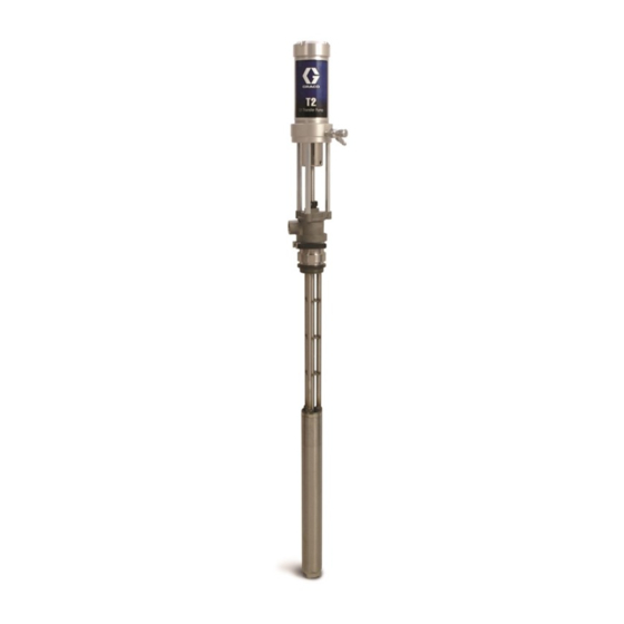
T2
2:1 Ratio Transfer Pump
For use with polyurethane foam, polyurea, and similar non-flammable materials. Not for
use in explosive atmospheres.
Model 295616 (55-gallon drum)
180 psi (1.2 MPa, 12 bar) Maximum Air Working Pressure
405 psi (2.7 MPa, 27 bar) Maximum Fluid Working Pressure
Model 261058 (15-gallon drum)
180 psi (1.2 MPa, 12 bar) Maximum Air Working Pressure
405 psi (2.7 MPa, 27 bar) Maximum Fluid Working Pressure
Important Safety Instructions
Read all warnings and instructions in this manual.
Save these instructions.
This manual is available in the following languages.
311882
English
312524
French
312525
German
312526
Italian
312527
Russian
312528
Spanish
312529
Swedish
312530
Chinese
312531
Korean
312532
Japanese
311882C
ti9889a
Advertisement
Table of Contents

Related Manuals for Graco T2


Summary of Contents for Graco T2
- Page 1 Instructions 2:1 Ratio Transfer Pump 311882C For use with polyurethane foam, polyurea, and similar non-flammable materials. Not for use in explosive atmospheres. Model 295616 (55-gallon drum) 180 psi (1.2 MPa, 12 bar) Maximum Air Working Pressure 405 psi (2.7 MPa, 27 bar) Maximum Fluid Working Pressure Model 261058 (15-gallon drum) 180 psi (1.2 MPa, 12 bar) Maximum Air Working Pressure 405 psi (2.7 MPa, 27 bar) Maximum Fluid Working Pressure...
-
Page 2: Table Of Contents
Pressure Relief Procedure ....10 Graco Information ......22 Flushing . - Page 3 Warnings WARNING EQUIPMENT MISUSE HAZARD Misuse can cause death or serious injury. • Do not operate the unit when fatigued or under the influence of drugs or alcohol. • Do not exceed the maximum working pressure or temperature rating of the lowest rated system component.
-
Page 4: Typical Installation
Typical Installation Typical Installation Typical Installation, without Circulation Key for F Reactor Proportioner Waste Containers Heated Hose Fluid Supply Lines (217382) Fluid Temperature Sensor (FTS) Feed Pumps Heated Whip Hose Agitator Fusion Spray Gun Desiccant Dryer Proportioner and Gun Air Supply Hose Bleed Lines/Over Pressure Relief Feed Pump Air Supply Lines (3/8 in. - Page 5 Typical Installation Typical Installation, with Circulation Key for F Reactor Proportioner Feed Pump Air Supply Lines (3/8 in. (76 mm) ID min) Heated Hose Fluid Supply Lines Fluid Temperature Sensor (FTS) Feed Pumps Heated Whip Hose Agitator Fusion Spray Gun Desiccant Dryer Proportioner and Gun Air Supply Hose Recirculation/Over Pressure Relief Return Hoses...
- Page 6 Typical Installation Typical Installation for Lubrication Applications Key for F Pump Air Regulator Grounded Air Hose Air Line Lubricator Grounded Fluid Hose Air Line Filter Pump Fluid Inlet Bleed-Type Master Air Valve (required, for pump) 1/4 npt(f) Pump Air Inlet Fluid Drain Valve (required) 1/2 npt(f) Pump Fluid Outlet Bung Adapter...
-
Page 7: Moisture Sensitivity Of Isocyanates
Moisture Sensitivity of Isocyanates Moisture Sensitivity of Isocyanate Hazard Isocyanates Isocyanates (ISO) are catalysts used in two component Read material manufacturer’s warnings and material foam and polyurea coatings. ISO will react with moisture MSDS to know the specific hazards of isocyanates. (such as humidity) to form small, hard, abrasive crystals, Use equipment in a well-ventilated area. -
Page 8: Setup
Setup Setup 1. Apply thread sealant to the male threads of the air 3. Use labels (70) provided to identify the appropriate needle valve (48) and the quick disconnect fitting pump for your material. See F . 5 and F . -
Page 9: Grounding The System
Setup 5. Install air line (3/8 in. (76 mm) ID minimum) with 2. Air compressor: according to manufacturer’s recom- quick disconnect air coupler (52) provided. See F mendations. 3. Fluid hoses: use only grounded hoses with a maxi- mum of 300 ft (91 m) combined hose length to ensure grounding continuity. -
Page 10: Operation
Operation Operation Pressure Relief Procedure 1. Follow Pressure Relief Procedure, page 10. 2. Place suction tube in grounded metal drum contain- ing cleaning fluid. 3. Set pump to lowest possible fluid pressure, and start Trapped air can cause the pump to cycle unexpectedly, pump. -
Page 11: Air Motor Repair
Air Motor Repair Air Motor Repair 1. Remove cap (1), cylinder (4), and square gaskets 3. Remove 3 screws (16) from top of air piston. (3*). Inspect all parts, including spring under cap Remove valve disk (8) and spacers (11). Remove (not shown in F . -
Page 12: Pump Lower Repair
Pump Lower Repair Pump Lower Repair 5. Remove dowel pin (19) and take piston cap (17) off transfer shaft (20). Remove o-ring (50*) from piston cap. Inspect all parts for damage. See F . 14. 1. Use a chain wrench near the top of the suction tube at the point indicated in F . - Page 13 Pump Lower Repair 2. With the foot valve still in place to support the suc- tion tube, use a chain wrench near the bottom of the suction tube at the point indicated in F . 17, to loosen the suction tube (44) from the pump body (34).
- Page 14 Pump Lower Repair 9. Remove spring pin (55) and slide upper fluid piston 11. Unscrew mounting flange (26) from pump body (34). assembly down and off the transfer shaft (20). See Remove o-ring (32*) and PTFE gasket (33*) from . 21. pump body (34).
-
Page 15: Reassembly
Reassembly Reassembly To reassemble the pump lower and air motor, reverse See Air Motor Repair, step 2 and step 3 (F . 11 the steps on the preceding pages. Follow the torque and F . 12) for special notes on reassembly. requirements listed in the Parts - Model 295616 draw- ing on page 16. -
Page 16: Parts - Model 295616
Parts - Model 295616 Parts - Model 295616 ✓56 ✓40 ✓41 ✓38 ◆ ‡ ‡ ‡ ◆ ◆ ◆ ◆ ✓35 ◆ ◆ ✓55 ✓57 ✓38 ti9890A Lubricate all o-rings and seals before and after assembly Torque to 45-55 ft-lbs (61-74.5 N•m) Torque to 30-40 ft-lbs (40.6-54.2 N•m) Torque to 15-20 ft-lbs (20.3-27.1 N•m) Bung Adapter... - Page 17 Parts - Model 295616 Part Description Part Description 15B924 CLAMP, hopper 15J536 CAP, air cylinder 15B925 HANDLE, hopper clamp 157630 SPRING, tapered 15B926 PIN, pivot, hopper clamp PACKING, square 51h✓† 120207 O-RING 15J537 CYLINDER, air motor 52† 114558 COUPLER, air line 5◆...
-
Page 18: Parts - Model 261058
Parts - Model 261058 Parts - Model 261058 ✓★ ★ ✓40 ✓41 ✓38 ◆ ‡ ‡ ‡ ◆ ◆ *◆ ◆ ✓35 ★ ◆ ◆ ✓★ ✓★ ✓38 ti9890B ★ Lubricate all o-rings and seals before and after assembly Torque to 45-55 ft-lbs (61-74.5 N•m) Torque to 30-40 ft-lbs (40.6-54.2 N•m) Torque to 15-20 ft-lbs (20.3-27.1 N•m) Bung Adapter... - Page 19 Parts - Model 261058 Part Description Part Description 15B924 CLAMP, hopper 15J536 CAP, air cylinder 15B925 HANDLE, hopper clamp 157630 SPRING, tapered 15B926 PIN, pivot, hopper clamp PACKING, square 51h†✓ 120207 O-RING 15J537 CYLINDER, air motor 52† 114558 COUPLER, air line 5◆...
-
Page 20: Technical Data
Technical Data Technical Data Pressure Ratio ....... . . 2.25:1 Max fluid working pressure . -
Page 21: Performance Chart
Technical Data Performance Chart Calculate Fluid Outlet Pressure (black Calculate Pump Air Consumption (gray curves) curves) To calculate fluid outlet pressure (MPa/bar/psi) at a spe- To calculate pump air consumption (m /min or scfm) at a cific fluid flow (lpm/gpm) and operating air pressure specific fluid flow (lpm/gpm) and air pressure (MPa/bar/psi), use the following instructions and pump (MPa/bar/psi), use the following instructions and pump... -
Page 22: Graco Standard Warranty
With the exception of any special, extended, or limited warranty published by Graco, Graco will, for a period of twelve months from the date of sale, repair or replace any part of the equipment determined by Graco to be defective.