Table of Contents
Advertisement
Quick Links
Instructions
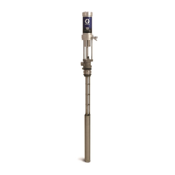
T2
2:1 Ratio Transfer Pump
For use with polyurethane foam, polyurea, and similar non-flammable materials. For
professional use only.
Not approved for use in European explosive atmosphere locations.
Model 295616 (55-gallon drum)
180 psi (1.2 MPa, 12 bar) Maximum Air Working Pressure
405 psi (2.7 MPa, 27 bar) Maximum Fluid Working Pressure
Important Safety Instructions
Read all warnings and instructions in
this manual before using the equipment.
Save these instructions.
311882U
EN
Advertisement
Table of Contents

Related Manuals for Graco T2


Summary of Contents for Graco T2
- Page 1 Instructions 311882U 2:1 Ratio Transfer Pump For use with polyurethane foam, polyurea, and similar non-flammable materials. For professional use only. Not approved for use in European explosive atmosphere locations. Model 295616 (55-gallon drum) 180 psi (1.2 MPa, 12 bar) Maximum Air Working Pressure 405 psi (2.7 MPa, 27 bar) Maximum Fluid Working Pressure Important Safety Instructions Read all warnings and instructions in...
-
Page 2: Table Of Contents
Grounding the System ....13 Graco Information......30... -
Page 3: Warnings
Warnings Warnings The following warnings are for the setup, use, grounding, maintenance, and repair of this equipment. The exclamation point symbol alerts you to a general warning and the hazard symbol refers to procedure-specific risk. Refer back to these warnings. Additional, product-specific warnings may be found throughout the body of this manual where applicable. - Page 4 Warnings WARNING PRESSURIZED EQUIPMENT HAZARD Fluid from the gun/dispense valve, leaks, or ruptured components can splash in the eyes or on skin and cause serious injury. • Follow Pressure Relief Procedure in this manual, when you stop spraying and before cleaning, checking, or servicing equipment.
-
Page 5: Important Isocyanate (Iso) Information
Important Isocyanate (ISO) Information Important Isocyanate (ISO) Information Isocyanates (ISO) are catalysts used in two component materials. Isocyanate Conditions Spraying or dispensing fluids that contain isocyanates creates potentially harmful mists, vapors, and atomized particulates. • Read and understand the fluid manufacturer’s warnings and Safety Data Sheets (SDSs) to know specific hazards and precautions related to isocyanates. -
Page 6: Material Self-Ignition
Important Isocyanate (ISO) Information Keep Components A and B Separate Spraying or dispensing fluids that contain isocyanates creates potentially harmful mists, vapors, and atomized particulates. Cross-contamination can result in cured material in • Read and understand the fluid manufacturer’s fluid lines which could cause serious injury or warnings and Safety Data Sheets (SDSs) to know damage equipment. -
Page 7: Foam Resins With 245 Fa Blowing Agents
Important Isocyanate (ISO) Information Foam Resins with 245 fa Changing Materials Blowing Agents NOTICE Some foam blowing agents will froth at temperatures Changing the material types used in your equipment above 90°F (33°C) when not under pressure, especially requires special attention to avoid equipment damage if agitated. -
Page 8: Typical Installation
Typical Installation Typical Installation Typical Installation, without Circulation ti11572a * Shown exposed for clarity. Wrap with tape during operation. . 1: Typical Installation, without Circulation Key: Reactor Proportioner Waste Containers Heated Hose Fluid Supply Lines (217382) Fluid Temperature Sensor (FTS) Feed Pumps Heated Whip Hose Agitator... -
Page 9: Typical Installation, With Circulation
Typical Installation Typical Installation, with Circulation ti11571a * Shown exposed for clarity. Wrap with tape during operation. . 2: Typical Installation, with Circulation Key: Reactor Proportioner Feed Pump Air Supply Lines (3/8 in. (76 mm) ID min) Heated Hose Fluid Supply Lines Fluid Temperature Sensor (FTS) Feed Pumps Heated Whip Hose... -
Page 10: Typical Installation For Lubrication Applications
Typical Installation Typical Installation for Lubrication Applications 01349 . 3: Typical Installation for Lubrication Applications Key: AA Pump Air Regulator AG Grounded Air Hose AB Air Line Lubricator AH Grounded Fluid Hose AC Air Line Filter AJ Pump Fluid Inlet AD Bleed-Type Master Air Valve (required, for pump) AK 1/4 npt(f) Pump Air Inlet AE Fluid Drain Valve (required) -
Page 11: Installation
Installation Installation Air Line Accessories Install the following accessories in the order shown in the Gun Fluid Manifold, page 9, using adapters as A bleed-type master air valve (D) and a fluid drain necessary: valve (E) are required in your system, to help reduce the risk of serious injury, including splashing fluid in An air line lubricator (AB) provides automatic air the eyes or on the skin, and injury from moving parts... -
Page 12: Setup
Setup Setup 1. Apply thread sealant to the male threads of the air 3. Use labels (70) provided to identify the appropriate needle valve (48) and the quick disconnect fitting pump for your material. See F . 5. (49) and install. See F Apply thread sealant 4. -
Page 13: Grounding The System
Setup 5. Install air line (3/8 in. (76 mm) ID minimum) with Pump: Connect Ground Wire (Y) to grounding screw quick disconnect air coupler (52) provided. See F (72) and tighten the screw securely. See F . 9. Connect the other end of the wire to a true earth ground. Make certain to comply with all National, State, and Local Electrical Codes. -
Page 14: Operation
Operation Operation Pressure Relief Procedure Flushing Follow the Pressure Relief Procedure whenever you see this symbol. To avoid fire and explosion, always ground equipment and waste container. To avoid static sparking and injury from splashing, always flush at the lowest possible pressure. Hot solvent may ignite. -
Page 15: Daily Startup
Operation Daily Startup NOTICE Never allow the pump to run dry of the fluid being 1. Verify that the air needle valve is closed. pumped. A dry pump will quickly accelerate to a high speed and could cause damage to the pump. If the 2. -
Page 16: Repair The Air Motor
Repair the Air Motor Repair the Air Motor 3. Series A air motors only: Loosen set screw (18) and unscrew air valve (5). If necessary to assist turning, wedge a screwdriver blade between the screw heads and the hex cap of air valve (5). Discard items 5, 13, 15, and 18. - Page 17 Repair the Air Motor 5. Align slot of shield (75) with piston hole and place 7. Slide air piston (21) out the top of the air motor base pin tool (69) in piston hole to prevent piston from (23). Remove o-ring (24*) from air motor base. turning.
-
Page 18: Repair The Pump Lower
Repair the Pump Lower Repair the Pump Lower 1. Relieve the pressure. Follow Pressure Relief Procedure, page 14. 1. Allow the fluid in the system to cool. 2. Use a chain wrench near the top of the suction tube at the point indicated in F . - Page 19 Repair the Pump Lower 8. Pull transfer shaft (20) out the bottom of pump body 10. Remove pins (55). See F . 21. (34). See F . 19. r_311880_14e_fig21 . 21 NOTE: Series A and B pumps were equipped with springs pins.
- Page 20 Repair the Pump Lower 12. Unscrew mounting flange (26) from pump body 14. Unscrew three fasteners (60) to remove the flange (34). Remove o-ring (32*) and PTFE gasket (33*) (26) and tie-rods (25). Slide the guard (75) out. from pump body (34). Inspect all parts for damage. Unscrew the tie rods (25) using the wrench flats at See F .
-
Page 21: Reassemble The Air Motor And The Pump Lower
Reassemble the Air Motor and the Pump Lower Reassemble the Air Motor and the Pump Lower To reassemble the pump lower and air motor, reverse NOTE: See Repair the Air Motor, page 16, step 4 and the steps on the preceding pages. Follow the torque step 5 (F . -
Page 22: Parts - Model 295616
Parts - Model 295616 Parts - Model 295616 56 40 41 42 38 73 35 71 38 Lubricate all o-rings and seals before and after assembly 51h Bung Adapter Torque to 45-55 ft-lb (61-74.5 N•m) Torque to 30-40 ft-lb (40.6-54.2 N•m) Torque to 15-20 ft-lb (20.3-27.1 N•m) Torque to 20-30 in-lb (2.2-3.3 N•m) - Page 23 169969 FITTING, air line 50* 108832 O-RING The T2 can be adapted for use in 250 gallon (946 liter) 253146 ADAPTER, bung totes. Tube Extension 24N451 increases the length by (includes 51a-51g) 6.25 in. (165 mm) to reach material in the bottom of 51a...
-
Page 24: Accessories
Accessories Accessories Grounding Clamp Part Description Qty. 214848 LUBRICATOR, air line; 8 oz (0.24 liter) Part Description Qty. bowl capacity; 1/2 npt(f) inlet and outlet 103538 CLAMP, ground Air Line Filter and Regulator Bleed-Type Master Air Valve 180 psi (1.3 MPa, 13 bar) Maximum Working 300 psi (2.1 MPa, 21 bar) Maximum Working Pressure Pressure... - Page 25 Accessories Part Description Qty. Part Description Qty. 202156 REGULATOR, air; 0-200 psi (0-14 bar) 208630 VALVE, ball; 1/2 npt(m) x 3/8 npt(f); for regulated pressure range; 3/8 npt(f) inlet non-corrosive fluids; carbon steel and and outlet PTFE 237534 VALVE, ball; 3/8 npt(m) x 3/8 npt(f); for corrosive fluids;...
-
Page 26: Performance Chart
Performance Chart Performance Chart Calculate Fluid Outlet Pressure Calculate Pump Air (black curves) Consumption (gray curves) To calculate fluid outlet pressure (MPa/bar/psi) at a To calculate pump air consumption (m /min or scfm) at specific fluid flow (lpm/gpm) and operating air pressure a specific fluid flow (lpm/gpm) and air pressure (MPa/bar/psi), use the following instructions and pump (MPa/bar/psi), use the following instructions and pump... -
Page 27: Dimensions
Dimensions Dimensions 1/4 npt inlet 3/4 npt outlet 54 in. (137.2 cm) 33.7 in. (85.6 cm) 311882U... - Page 28 Dimensions 311882U...
-
Page 29: Technical Specifications
Technical Specifications Technical Specifications T2, 2:1 Ratio Transfer Pump Metric Pressure ratio 2.25:1 Maximum fluid working pressure 405 psi 2.8 MPa, 28 bar Maximum air inlet pressure 180 psi 1.2 MPa, 12 bar Maximum continuous outlet flow 5 gpm 20 lpm Maximum intermittent outlet flow 7.5 gpm... -
Page 30: Graco Standard Warranty
With the exception of any special, extended, or limited warranty published by Graco, Graco will, for a period of twelve months from the date of sale, repair or replace any part of the equipment determined by Graco to be defective.