Table of Contents
Advertisement
Quick Links
User's Guide
EMG6726/8726-B10A
Dual-Band Wireless AC/N Gigabit Ethernet Gateway
Wireless AC Gigabit Ethernet Gateway with VoIP
Default Login Details
LAN IP Address
Login
Password
Copyright © 2019 Zyxel Communications Corporation
http://192.168.1.1
admin
See the device label
Version 5.13 Edition 1, 05/2019
Advertisement
Table of Contents

Related Manuals for ZyXEL Communications EMG8726-B10A


Summary of Contents for ZyXEL Communications EMG8726-B10A
- Page 1 User’s Guide EMG6726/8726-B10A Dual-Band Wireless AC/N Gigabit Ethernet Gateway Wireless AC Gigabit Ethernet Gateway with VoIP Default Login Details Version 5.13 Edition 1, 05/2019 LAN IP Address http://192.168.1.1 Login admin Password See the device label Copyright © 2019 Zyxel Communications Corporation...
- Page 2 IMPORTANT! READ CAREFULLY BEFORE USE. KEEP THIS GUIDE FOR FUTURE REFERENCE. Graphics in this book may differ slightly from the product due to differences in operating systems, operating system versions, or if you installed updated firmware/software for your device. Every effort has been made to ensure that the information in this manual is accurate.
-
Page 3: Document Conventions
Document Conventions Document Conventions Warnings and Notes These are how warnings and notes are shown in this guide. Warnings tell you about things that could harm you or your device. Note: Notes tell you other important information (for example, other things you may need to configure or helpful tips) or recommendations. - Page 4 Document Conventions Telephone Cell Tower Printer Telephone Jack Splitter EMG6726/8726-B10A User’s Guide...
-
Page 5: Table Of Contents
Contents Overview Contents Overview User’s Guide ............................. 16 Introducing the EMG ..........................17 The Web Configurator ......................... 27 Quick Start ............................. 34 Tutorials ..............................37 Technical Reference ........................59 Network Map and Status Screens ...................... 60 Broadband ............................64 Wireless ..............................77 Home Networking .......................... - Page 6 Contents Overview Backup/Restore ..........................266 Diagnostic ............................269 Troubleshooting ..........................274 Appendices ............................ 279 EMG6726/8726-B10A User’s Guide...
-
Page 7: Table Of Contents
Table of Contents Table of Contents Document Conventions ........................3 Contents Overview ..........................5 Table of Contents ..........................7 Part I: User’s Guide..................16 Chapter 1 Introducing the EMG......................... 17 1.1 Overview ............................17 1.1.1 Internet Access ........................17 1.1.2 Ethernet WAN ........................17 1.1.3 Dual-Band .......................... - Page 8 Table of Contents Chapter 4 Tutorials .............................. 37 4.1 Overview ............................37 4.2 Setting Up a New WAN Connection .................... 37 4.3 Setting Up a Secure Wireless Network ..................40 4.3.1 Configuring the Wireless Network Settings ................. 40 4.3.2 Using WPS ..........................42 4.3.3 Connecting to the EMG’s Wi-Fi Network Manually (No WPS) ..........
- Page 9 Table of Contents 7.1.2 What You Need to Know ..................... 77 7.2 The WiFi Screen ..........................78 7.2.1 The WiFi Edit Screen ......................78 7.3 The Guest WiFi Screen ........................80 7.3.1 Edit Guest WiFi ........................81 7.4 The WPS Screen ..........................82 7.5 The Advanced Screen ........................
- Page 10 Table of Contents Chapter 9 Routing ............................. 126 9.1 Overview ............................126 9.2 The Routing Screen ........................126 9.2.1 Add/Edit Static Route ......................127 9.3 The DNS Route Screen ......................... 128 9.3.1 The DNS Route Add Screen ....................129 9.4 The Policy Route Screen ......................130 9.4.1 Add/Edit Policy Route ......................
- Page 11 Table of Contents 11.7.1 Add/Edit Address Mapping Rule ..................164 11.8 The Sessions Screen ........................165 11.9 Technical Reference ........................165 11.9.1 NAT Definitions ........................166 11.9.2 What NAT Does ......................... 166 11.9.3 How NAT Works ........................167 11.9.4 NAT Application ........................ 167 Chapter 12 Dynamic DNS Setup........................
- Page 12 Table of Contents Chapter 17 Firewall ............................. 185 17.1 Overview ............................. 185 17.1.1 What You Can Do in this Chapter ................... 185 17.1.2 What You Need to Know ....................186 17.2 The Firewall Screen ........................186 17.3 The Protocol Screen ........................187 17.3.1 Add/Edit a Service ......................
- Page 13 Table of Contents 22.1 Overview ............................. 208 22.1.1 What You Can Do in this Chapter ................... 208 22.1.2 What You Need to Know About VoIP ................208 22.2 Before You Begin ........................209 22.3 SIP Account ..........................209 22.3.1 SIP Account Add/Edit ....................... 210 22.4 SIP Service Provider ........................
- Page 14 Table of Contents Chapter 27 Multicast Status ..........................246 27.1 Overview ............................. 246 27.2 The IGMP Status Screen ......................246 27.3 The MLD Status Screen ....................... 246 Chapter 28 System.............................. 248 28.1 Overview ............................. 248 28.2 The System Screen ........................248 Chapter 29 User Account...........................
- Page 15 Table of Contents 34.2 The Log Settings Screen ......................261 34.2.1 Example E-mail Log ......................262 Chapter 35 Firmware Upgrade .......................... 264 35.1 Overview ............................. 264 35.2 The Firmware Screen ........................264 Chapter 36 Backup/Restore ..........................266 36.1 Overview ............................. 266 36.2 The Backup/Restore Screen ......................
-
Page 16: User's Guide
User’s Guide... -
Page 17: Introducing The Emg
EMG refers to these models as outlined below. • EMG6726-B10A • EMG8726-B10A The EMG is an Ethernet gateway providing triple-play services with optimized HD IPTV services for the home or office. This model offers a Gigabit Ethernet (GbE) WAN port. The EMG offers 2.4G and 5G Wi-Fi networks that can operate simultaneously. -
Page 18: Dual-Band
Chapter 1 Introducing the EMG Figure 1 EMG’s Internet Access Application: Ethernet WAN 1.1.3 Dual-Band The EMG is a dual-band gateway that can use both 2.4G and 5G networks at the same time. You could use the 2.4 GHz band for regular Internet surfing and downloading while using the 5 GHz band for time sensitive traffic like high-definition video, music, and gaming. -
Page 19: Triple Play
Chapter 1 Introducing the EMG 1.1.4 Triple Play Triple play means using broadband Internet access, VoIP and streaming video/audio media, all at the same time with no noticeable loss in bandwidth. Figure 3 Triple Play Example IP Phone Smart TV 1.1.5 Wireless Access The EMG is a wireless Access Point (AP) for IEEE 802.11b/g/n/a/ac wireless clients, such as notebook computers, iPads, smartphones, etc. -
Page 20: Good Habits For Managing The Emg
Chapter 1 Introducing the EMG • Web Configurator. This is recommended for everyday management of the EMG using a (supported) web browser. 1.3 Good Habits for Managing the EMG Do the following things regularly to make the EMG more secure and to manage the EMG more effectively. -
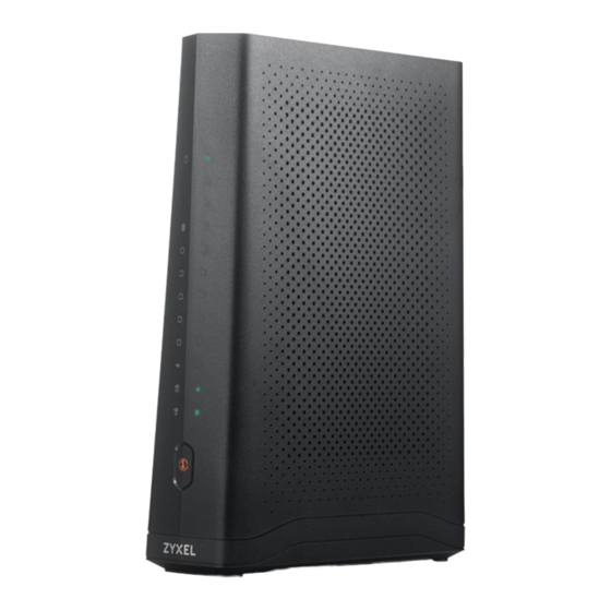
Page 21: Leds (Lights)
Chapter 1 Introducing the EMG Figure 6 LEDs on the EMG8726-B10A 1.4.2 LEDs (Lights) The following table describes the LEDs. None of the LEDs are on if the EMG is not receiving power. Table 2 EMG6726-B10A LED Descriptions COLOR STATUS... - Page 22 The EMG is setting up a WPS connection with a 2.4 GHz or 5 GHz wireless client. The 2.4 GHz or 5GHz wireless network is not activated. Amber WPS is enabled. WPS is disabled. Table 3 EMG8726-B10A LED Descriptions COLOR STATUS DESCRIPTION Green The EMG is receiving power and ready for use.
-
Page 23: Using The Wps Button
Chapter 1 Introducing the EMG Table 3 EMG8726-B10A LED Descriptions (continued) COLOR STATUS DESCRIPTION Green The 2.4 GHz or 5 GHz wireless network is activated. Blinking The EMG is communicating with 2.4 GHz or 5 GHz wireless clients. WiFi 2.4G... -
Page 24: The Reset Button
Chapter 1 Introducing the EMG Figure 7 EMG67256-B10A’s Rear Panel Figure 8 EMG8726-B10A’s Rear Panel The following table describes the items on the rear panel. Table 4 Rear Panel Ports LABEL DESCRIPTION ETHERNET1 ~ Connect computers or other Ethernet devices to Ethernet ports for Internet ETHERNET4 access. -
Page 25: Wall Mounting
Chapter 1 Introducing the EMG 1.4.6 Wall Mounting You may need screw anchors if mounting on a concrete or brick wall. Table 5 Wall Mounting Information Distance between holes 88 mm Screws Screw anchors (optional) The following figure introduces the specifications of the screws and screws anchors for wall mounting. Figure 9 Screws &... - Page 26 Chapter 1 Introducing the EMG Figure 10 Wall Mounting Example EMG6726/8726-B10A User’s Guide...
-
Page 27: The Web Configurator
H A P T E R The Web Configurator 2.1 Overview The web configurator is an HTML-based management interface that allows easy setup and management via Internet browser. Use Internet Explorer 8.0 and later versions or Mozilla Firefox 3 and later versions or Safari 2.0 and later versions. - Page 28 Chapter 2 The Web Configurator Figure 12 Change Password Screen The Quick Start Wizard screen appears. You can configure basic Internet access, and wireless settings. Chapter 3 on page 34 for more information. After you finished or closed the Quick Start Wizard screen, the Network Map page appears. Figure 13 Network Map: List View Mode Click Status to display the Status screen, where you can view the EMG’s interface and system information.
-
Page 29: Web Configurator Layout
Chapter 2 The Web Configurator 2.2 Web Configurator Layout Figure 14 Screen Layout As illustrated above, the main screen is divided into these parts: • A - title bar • B - main window • C - navigation panel 2.2.1 Title Bar The title bar provides some icons in the upper right corner. -
Page 30: Navigation Panel
Chapter 2 The Web Configurator Table 6 Web Configurator Icons in the Title Bar ICON DESCRIPTION Quick Start: Click this icon to open screens where you can configure the EMG’s time zone Internet access, and wireless settings. Logout: Click this icon to log out of the web configurator. 2.2.2 Navigation Panel Use the menu items on the navigation panel to open screens to configure EMG features. - Page 31 Certificates Local Certificates Use this screen to view a summary list of certificates and manage certificates and certification requests. Trusted CA Use this screen to view and manage the list of the trusted CAs. VoIP (for EMG8726-B10A) EMG6726/8726-B10A User’s Guide...
- Page 32 Chapter 2 The Web Configurator Table 7 Navigation Panel Summary (continued) LINK FUNCTION SIP Account Use this screen to set up information about your SIP account and configure audio settings such as volume levels for the phones connected to the VMG. SIP Service Use this screen to configure the SIP server information, QoS for VoIP calls, Provider...
- Page 33 Chapter 2 The Web Configurator Table 7 Navigation Panel Summary (continued) LINK FUNCTION SNMP SNMP Use this screen to configure SNMP (Simple Network Management Protocol) settings. Time Time Use this screen to change your EMG’s time and date. E-mail E-mail Use this screen to configure up to two mail servers and sender addresses Notification Notification...
-
Page 34: Quick Start
H A P T E R Quick Start 3.1 Overview Use the Quick Start screens to configure the EMG’s time zone, basic Internet access, and wireless settings. Note: See the technical reference chapters (starting on Chapter 4 on page 37) for background information on the features in this chapter. - Page 35 Chapter 3 Quick Start Figure 16 Quick Start - Internet Connection Turn the wireless LAN on or off. If you keep it on, record the security settings so you can configure your wireless clients to connect to the EMG. Click Save. Figure 17 Quick Start - Wireless Setting Your EMG saves your settings and attempts to connect to the Internet.
- Page 36 Chapter 3 Quick Start Figure 18 Quick Start - Result Summary EMG6726/8726-B10A User’s Guide...
-
Page 37: Tutorials
H A P T E R Tutorials 4.1 Overview This chapter shows you how to use the EMG’s various features. • Setting Up a New WAN Connection, see page 37 • Setting Up a Secure Wireless Network, see page 40 •... - Page 38 Chapter 4 Tutorials Encapsulation PPPoE IPv6/IPv4 Mode IPv4 Only Account Information PPP User Name 1234@WAN-Ex.com PPP Password ABCDEF! Static IP Address 192.168.1.32 Others PPP Connection Trigger: Auto Connect PPPoE Passthrough: Disable NAT Enable: Enable IGMP Proxy Enable: Enable Apply as Default Gateway: Enable VLAN Active: Disable Select the Active check box.
- Page 39 Chapter 4 Tutorials You should see a summary of your new WAN connection setup in the Broadband screen as follows. EMG6726/8726-B10A User’s Guide...
-
Page 40: Setting Up A Secure Wireless Network
Chapter 4 Tutorials Try to connect to a website to see if you have correctly set up your Internet connection. 4.3 Setting Up a Secure Wireless Network Thomas wants to set up a wireless network so that he can use his notebook to access the Internet. In this wireless network, the EMG serves as an access point (AP), and the notebook is the wireless client. - Page 41 Chapter 4 Tutorials The WiFi Edit screen displays. Select WPA2-PSK as the security type. Configure the screen using the provided parameters (see page 40). Click Save. Go to the Wireless > Advanced screen and select 802.11b/g/n Mixed in the 802.11 Mode field in the 2.4G Advanced Settings section.
-
Page 42: Using Wps
Chapter 4 Tutorials Thomas can now use the WPS feature to establish a wireless connection between his notebook and the EMG (see Section 4.3.2 on page 42). He can also use the notebook’s wireless client to search for the EMG (see Section 4.3.3 on page 44). - Page 43 Chapter 4 Tutorials You can either press the WPS button on the EMG’s panel or click the Connect button for the corresponding 2.4G or 5G wireless band in the Network Setting > Wireless > WPS screen. Go to your phone settings and turn on Wi-Fi. Open the Wi-Fi networks list and tap WPS Push Button or the WPS icon ( Note: It doesn’t matter which button is pressed first.
-
Page 44: Connecting To The Emg's Wi-Fi Network Manually (No Wps)
Chapter 4 Tutorials Example WPS Process: PBC Method Wireless Client WITHIN 2 MINUTES Press and hold for more than 5 seconds SECURITY INFO COMMUNICATION 4.3.3 Connecting to the EMG’s Wi-Fi Network Manually (No WPS) In this example, we change the EMG’s wireless settings, and then manually select the EMG’s new SSID and enter the Wi-Fi key to connect a wireless client to the EMG. - Page 45 Chapter 4 Tutorials Enter SSID_Example as the wireless name. Set WiFi security type to WPA2-PSK and enter ThisismyWPA- PSKpre-sharedkey in the Pre-Shared Key field. Click Save. Go to the Network Setting > Wireless > Advanced screen and select Auto in the Channel field to have the EMG scan for and select an available channel automatically.
-
Page 46: Configure Your Notebook
Chapter 4 Tutorials 4.3.5 Configure Your Notebook Note: In this example, we use a Windows 7 laptop that has a built-in wireless adapter as the wireless client. The EMG supports IEEE 802.11a/g/n/b/ac wireless clients. Make sure that your notebook or computer’s wireless adapter supports one of these standards. - Page 47 Chapter 4 Tutorials The following screen displays if WPS is enabled on the EMG but you didn’t press the WPS button. Click Connect using as security key instead. Type the security key in the following screen. Click OK. Check the status of your wireless connection in the screen below. EMG6726/8726-B10A User’s Guide...
-
Page 48: Setting Up Multiple Wireless Groups
Chapter 4 Tutorials If the wireless client keeps trying to connect to or acquiring an IP address from the EMG, make sure you entered the correct security key. If the connection has limited or no connectivity, make sure the EMG is connected to a router with the DHCP server enabled. - Page 49 Chapter 4 Tutorials Click Network Setting > Wireless > WiFi > Edit to open the WiFi Edit screen. Use this screen to set up the family’s general wireless network group. Configure the screen using the provided parameters and click Save. Click Network Setting >...
- Page 50 Chapter 4 Tutorials In the Guest WiFi screen, click an Edit icon next to a 2.4G “extra WiFi” network to configure the third wireless network group. Configure the screen using the provided parameters and click Save. Check the status of Guest and APP in the Guest WiFi screen. The screen also displays the remaining available time for using the Guest WiFi network at the upper right corner.
-
Page 51: Configuring Static Route For Routing To Another Network
Chapter 4 Tutorials 4.5 Configuring Static Route for Routing to Another Network In order to extend your Intranet and control traffic flowing directions, you may connect a router to the EMG’s LAN. The router may be used to separate two department networks. This tutorial shows how to configure a static routing rule for two network routings. - Page 52 Chapter 4 Tutorials This tutorial uses the following example IP settings: Table 8 IP Settings in this Tutorial DEVICE / COMPUTER IP ADDRESS The EMG’s WAN 172.16.1.1 The EMG’s LAN 192.168.1.1 IP Type IPv4 Use Interface ETHWAN 192.168.1.34 R’s N1 192.168.1.253 R’s N2 192.168.10.2...
-
Page 53: Configuring Qos Queue And Class Setup
Chapter 4 Tutorials Click OK. Now B should be able to receive traffic from A. You may need to additionally configure B’s firewall settings to allow specific traffic to pass through. 4.6 Configuring QoS Queue and Class Setup This section contains tutorials on how you can configure the QoS screen. Let’s say you are a team leader of a small sales branch office. - Page 54 Chapter 4 Tutorials Tutorial: Advanced > QoS Click Queue Setup > Add new Queue to create a new queue. In the screen that opens, check Active and enter or select the following values: • Name: E-mail • Interface: WAN • Priority: 1 (High) •...
- Page 55 Chapter 4 Tutorials Tutorial: Advanced > QoS > Class Setup FIELD TO HOW TO CONFIGURE CONFIGURE Class Name Give a class name to this traffic, such as E-mail in this example. From Interface This is the interface from which the traffic will be coming from. Select LAN1 for this example. Ether Type Select IP to identify the traffic source by its IP address or MAC address.
-
Page 56: Access The Emg Using Ddns
Chapter 4 Tutorials This maps e-mail traffic coming from port 25 to the highest priority, which you have created in the previous screen (see the IP Protocol field). This also maps your computer’s IP address and MAC address to the E-mail queue (see the Source fields). 4.7 Access the EMG Using DDNS If you connect your EMG to the Internet and it uses a dynamic WAN IP address, it is inconvenient for you to manage the device from the Internet. -
Page 57: Configuring Ddns On Your Emg
Chapter 4 Tutorials 4.7.2 Configuring DDNS on Your EMG Configure the following settings in the Network Setting > DNS > Dynamic DNS screen. • Select Enable Dynamic DNS. • Select www.DynDNS.com as the service provider. • Type zyxelrouter.dyndns.org in the Host Name field. •... - Page 58 Chapter 4 Tutorials Click Security > MAC Filter to open the MAC Filter screen. Select the Enable check box to activate MAC filter function. Select Allow. Then enter the host name and MAC address of Thomas’ computer in this screen. Click Apply.
-
Page 59: Technical Reference
Technical Reference... -
Page 60: Network Map And Status Screens
H A P T E R Network Map and Status Screens 5.1 Overview After you log into the Web Configurator, the Status screen appears. You can use the Status screen to look at the current status of the EMG, system resources, and interfaces (LAN, WAN, and WLAN). 5.2 The Status Screen Use this screen to view the status of the EMG. - Page 61 Chapter 5 Network Map and Status Screens Each field is described in the following table. Table 9 Status Screen LABEL DESCRIPTION Refresh Interval Select how often you want the EMG to update this screen. Device Information Host Name This field displays the EMG system name. It is used for identification. Model Number This shows the model number of your EMG.
-
Page 62: The Network Map Screen
Chapter 5 Network Map and Status Screens Table 9 Status Screen (continued) LABEL DESCRIPTION Security Firewall This displays the firewall’s current security level. System Status System Up Time This field displays how long the EMG has been running since it last started up. The EMG starts up when you plug it in, when you restart it (Maintenance >... - Page 63 Chapter 5 Network Map and Status Screens If you want to view information about a client, click Info of the entry and the following screen displays. If you prefer to view the layout of the device and its client icons, click Icon View in the Viewing Mode selection box.
-
Page 64: Broadband
H A P T E R Broadband 6.1 Overview This chapter discusses the EMG’s Broadband screens. Use these screens to configure your EMG for Internet access. A WAN (Wide Area Network) connection is an outside connection to another network or the Internet. It connects your private networks, such as a LAN (Local Area Network) and other networks, so that a computer in one location can communicate with computers in other locations. - Page 65 Chapter 6 Broadband WAN IP Address The WAN IP address is an IP address for the EMG, which makes it accessible from an outside network. It is used by the EMG to communicate with other devices in other networks. It can be static (fixed) or dynamically assigned by the ISP each time the EMG tries to access the Internet.
- Page 66 Chapter 6 Broadband IPv6 Rapid Deployment Use IPv6 Rapid Deployment (6rd) when the local network uses IPv6 and the ISP has an IPv4 network. When the EMG has an IPv4 WAN address and you set IPv4/IPv6 Mode to IPv4 Only, you can enable 6rd to encapsulate IPv6 packets in IPv4 packets to cross the ISP’s IPv4 network.
-
Page 67: Before You Begin
Chapter 6 Broadband Figure 24 Dual Stack Lite 6.1.3 Before You Begin You need to know your Internet access settings such as encapsulation and WAN IP address. Get this information from your ISP. 6.2 The Broadband Screen Use this screen to change your EMG’s Internet access settings. Click Network Setting > Broadband from the menu. -
Page 68: Add/Edit Internet Connection
Chapter 6 Broadband Table 11 Network Setting > Broadband (continued) LABEL DESCRIPTION 802.1q This indicates the VLAN ID number assigned to traffic sent through this connection. This displays N/A when there is no VLAN ID number assigned. Igmp Proxy This shows whether the EMG act as an IGMP proxy on this connection. This shows whether NAT is activated or not for this connection. - Page 69 Chapter 6 Broadband Figure 26 Network Setting > Broadband > Add New WAN Interface/Edit (Routing Mode) The following table describes the labels in this screen. Table 12 Network Setting > Broadband > Add New WAN Interface/Edit (Routing Mode) LABEL DESCRIPTION General Active Select Enable to activate this WAN interface.
- Page 70 Chapter 6 Broadband Table 12 Network Setting > Broadband > Add New WAN Interface/Edit (Routing Mode) (continued) LABEL DESCRIPTION IPv4/IPv6 Mode Select IPv4 Only if you want the EMG to run IPv4 only. Select IPv4 IPv6 DualStack to allow the EMG to run IPv4 and IPv6 at the same time. Select IPv6 Only if you want the EMG to run IPv6 only.
- Page 71 Chapter 6 Broadband Table 12 Network Setting > Broadband > Add New WAN Interface/Edit (Routing Mode) (continued) LABEL DESCRIPTION Fullcone NAT Select Enable to enable full cone NAT on this connection. This field is available only when you Enable activate NAT. In full cone NAT, the EMG maps all outgoing packets from an internal IP address and port to a single IP address and port on the external network.
- Page 72 Chapter 6 Broadband Table 12 Network Setting > Broadband > Add New WAN Interface/Edit (Routing Mode) (continued) LABEL DESCRIPTION Service Provider Enter an IPv6 prefix for tunneling IPv6 traffic to the ISP’s border relay router and connecting to the IPv6 Prefix native IPv6 Internet.
- Page 73 Chapter 6 Broadband Table 12 Network Setting > Broadband > Add New WAN Interface/Edit (Routing Mode) (continued) LABEL DESCRIPTION Primary DNS Enter the first IPv6 DNS server address assigned by the ISP. Server Secondary DNS Enter the second IPv6 DNS server address assigned by the ISP. Server Click OK to save your changes back to the EMG.
-
Page 74: Technical Reference
Chapter 6 Broadband Table 13 Network Setting > Broadband > Add New WAN Interface/Edit (Ethernet-Bridge) (continued) LABEL DESCRIPTION Active Select Enable to enable VLAN on this WAN interface. 802.1p IEEE 802.1p defines up to 8 separate traffic types by inserting a tag into a MAC-layer frame that contains bits to define class of service. - Page 75 Chapter 6 Broadband IP Address Assignment A static IP is a fixed IP that your ISP gives you. A dynamic IP is not fixed; the ISP assigns you a different one each time. The Single User Account feature can be enabled or disabled if you have either a dynamic or static IP.
- Page 76 Chapter 6 Broadband Internet Group Multicast Protocol (IGMP) is a network-layer protocol used to establish membership in a Multicast group - it is not used to carry user data. IGMP version 2 (RFC 2236) is an improvement over version 1 (RFC 1112) but IGMP version 1 is still in wide use. If you would like to read more detailed information about interoperability between IGMP version 2 and version 1, please see sections 4 and 5 of RFC 2236.
-
Page 77: Wireless
H A P T E R Wireless 7.1 Overview This chapter describes the EMG’s Network Setting > Wireless screens. Use these screens to set up your EMG’s wireless connection. 7.1.1 What You Can Do in this Chapter This section describes the EMG’s Wireless screens. Use these screens to set up your EMG’s wireless connection. -
Page 78: The Wifi Screen
Chapter 7 Wireless 7.2 The WiFi Screen Use this screen to view the wireless network name and password. You can also click the Edit icon to configure the settings. Click Network Setting > Wireless to open the WiFi screen. Figure 28 Network Setting > Wireless > WiFi Figure 29 Network Setting >... - Page 79 Chapter 7 Wireless Figure 30 Network Setting > Wireless > WiFi > Edit Figure 31 Network Setting > Wireless > WiFi > Edit (Without Keeping 2.4G and 5G WiFi Network Name The Same) The following table describes the general wireless LAN labels in this screen. Table 15 Network Setting >...
-
Page 80: The Guest Wifi Screen
Chapter 7 Wireless Table 15 Network Setting > Wireless > WiFi > Edit (continued) LABEL DESCRIPTION WiFi Security Select WPA2-PSK to add security on this wireless network. The WPA2-PSK security mode is a Type newer, more robust version of the WPA encryption standard. It offers wireless clients a better and secure connection. -
Page 81: Edit Guest Wifi
Chapter 7 Wireless Table 16 Network Setting > Wireless > Guest WiFi (continued) LABEL DESCRIPTION Password This field displays the password used to connect to this extra wireless network. Action Click the Edit icon to configure the WiFi network profile. 7.3.1 Edit Guest WiFi Use this screen to edit a guest WiFi or an extra WiFi settings. -
Page 82: The Wps Screen
Chapter 7 Wireless 7.4 The WPS Screen Use this screen to use the WiFi Protected Setup (WPS) function on your EMG. WPS allows you to quickly set up a wireless network with strong security, without having to configure security settings manually. Set up each WPS connection between two devices. Both devices must support WPS. - Page 83 Chapter 7 Wireless Figure 35 Network Setting > Wireless > Advanced EMG6726/8726-B10A User’s Guide...
- Page 84 Chapter 7 Wireless The following table describes the labels in this screen. Table 19 Network Setting > Wireless > Advanced LABEL DESCRIPTION 2.4G Advanced Settings / 5G Advanced Settings Hide WiFi Select this check box to hide the wireless band’s network name (SSID) in the outgoing beacon Network Name frame so a station cannot obtain the SSID through scanning using a site survey tool or any wireless clients.
-
Page 85: The Channel Status Screen
RADAR devices. If your device is operating near an area known to have RADAR devices, it is recommended to disable DFS Channel to avoid interfering with their signal. Note: At the time of writing, this field is not available for the EMG8726-B10A. MU-MIMO Select Enable to allow accelerated and simultaneous WiFi service when there are multiple MUMIMO (Multi User-Multiple input, Multiple Output) ready devices connected to the EMG. - Page 86 Chapter 7 Wireless Figure 36 Network Setting > Wireless > Channel Status EMG6726/8726-B10A User’s Guide...
-
Page 87: The Mesh Screen
Chapter 7 Wireless 7.7 The MESH Screen Use this screen to enable or disable Zyxel MESH (Multy Pro). It supports AP steering and Band steering. AP steering allows wireless clients to roam seamlessly between Multy-Pro-supported devices in your MESH network by using the same SSID and WiFi password. Also, AP steering helps monitor wireless clients and drop their connections to optimize the EMG bandwidth when the clients are idle or have a low signal. - Page 88 Chapter 7 Wireless 3 Press the WPS button for more than five seconds on the EMG. Click Add Extender in the Multy Pro App. Install from Google Play or the Apple App store. The following figure shows the Multy Pro application. Device Z is the EMG. Device A is a Multy- Prosupported extender in AP mode.
-
Page 89: Technical Reference
Chapter 7 Wireless Figure 39 Network Setting > Wireless > MESH > A Warning When You Enable MESH 7.8 Technical Reference This section discusses wireless LANs in depth. For more information, see Appendix B on page 286. 7.8.1 Wireless Network Overview Wireless networks consist of wireless clients, access points and bridges. - Page 90 Chapter 7 Wireless Figure 40 Example of a Wireless Network The wireless network is the part in the blue circle. In this wireless network, devices A and B use the access point (AP) to interact with the other devices (such as the printer) or with the Internet. Your EMG is the AP. Every wireless network must follow these basic guidelines.
-
Page 91: Additional Wireless Terms
Chapter 7 Wireless 7.8.2 Additional Wireless Terms The following table describes some wireless network terms and acronyms used in the EMG’s Web Configurator. Table 22 Additional Wireless Terms TERM DESCRIPTION RTS/CTS Threshold In a wireless network which covers a large area, wireless devices are sometimes not aware of each other’s presence. - Page 92 Chapter 7 Wireless 7.8.3.1 SSID Normally, the EMG acts like a beacon and regularly broadcasts the SSID in the area. You can hide the SSID instead, in which case the EMG does not broadcast the SSID. In addition, you should change the default SSID to something that is difficult to guess.
-
Page 93: Signal Problems
Chapter 7 Wireless The types of encryption you can choose depend on the type of authentication. (See Section 7.8.3.3 on page 92 for information about this.) Table 23 Types of Encryption for Each Type of Authentication NO AUTHENTICATION Weakest No Security Strongest WPA2-PSK For example, If users do not log in to the wireless network, you can choose no encryption or WPA2-PSK. -
Page 94: Mbssid
Chapter 7 Wireless Figure 41 Basic Service set 7.8.6 MBSSID Traditionally, you need to use different APs to configure different Basic Service Sets (BSSs). As well as the cost of buying extra APs, there is also the possibility of channel interference. The EMG’s MBSSID (Multiple Basic Service Set IDentifier) function allows you to use one access point to provide several BSSs simultaneously. -
Page 95: Wifi Protected Setup (Wps)
Chapter 7 Wireless Use long preamble if you are unsure what preamble mode other wireless devices on the network support, and to provide more reliable communications in busy wireless networks. Use short preamble if you are sure all wireless devices on the network support it, and to provide more efficient communications. - Page 96 Chapter 7 Wireless enrollee (the device that receives network and security settings. The registrar creates a secure EAP (Extensible Authentication Protocol) tunnel and sends the network name (SSID) and the WPA2-PSK pre- shared key to the enrollee. Whether WPA2-PSK is used depends on the standards supported by the devices.
- Page 97 Chapter 7 Wireless 7.8.8.3 Example WPS Network Setup This section shows how security settings are distributed in an example WPS setup. The following figure shows an example network. In step 1, both AP1 and Client 1 are unconfigured. When WPS is activated on both, they perform the handshake. In this example, AP1 is the registrar, and Client 1 is the enrollee.
- Page 98 Chapter 7 Wireless Figure 45 WPS: Example Network Step 3 EXISTING CONNECTION CLIENT 1 REGISTRAR CLIENT 2 ENROLLEE 7.8.8.4 Limitations of WPS WPS has some limitations of which you should be aware. • WPS works in Infrastructure networks only (where an AP and a wireless client communicate). It does not work in Ad-Hoc networks (where there is no AP).
- Page 99 Chapter 7 Wireless point is the WPS registrar, the enrollee, or was not involved in the WPS handshake; a rogue device must still associate with the access point to gain access to the network. Check the MAC addresses of your wireless clients (usually printed on a label on the bottom of the device). If there is an unknown MAC address you can remove it or reset the AP.
-
Page 100: Home Networking
H A P T E R Home Networking 8.1 Overview A Local Area Network (LAN) is a shared communication system to which many networking devices are connected. It is usually located in one immediate area such as a building or floor of a building. Use the LAN screens to help you configure a LAN DHCP server and manage IP addresses. -
Page 101: What You Need To Know
Chapter 8 Home Networking 8.1.2 What You Need To Know 8.1.2.1 About LAN IP Address IP addresses identify individual devices on a network. Every networking device (including computers, servers, routers, printers, etc.) needs an IP address to communicate across the network. These networking devices are also known as hosts. -
Page 102: Before You Begin
Chapter 8 Home Networking • Assigning lease times to mappings Windows Messenger is an example of an application that supports NAT traversal and UPnP. See the Chapter 11 on page 153 for more information on NAT. Cautions with UPnP The automated nature of NAT traversal applications in establishing their own services and opening firewall ports may present network security issues. - Page 103 Chapter 8 Home Networking Click Apply to save your settings. Figure 46 Network Setting > Home Networking > LAN Setup EMG6726/8726-B10A User’s Guide...
- Page 104 Chapter 8 Home Networking The following table describes the fields in this screen. Table 24 Network Setting > Home Networking > LAN Setup LABEL DESCRIPTION Interface Group Group Name Select the interface group name for which you want to configure LAN settings. See Chapter 15 on page 179 for how to create a new interface group.
- Page 105 Chapter 8 Home Networking Table 24 Network Setting > Home Networking > LAN Setup (continued) LABEL DESCRIPTION LAN IPv6 Mode Setup IPv6 Active Select Enable to activate the IPv6 mode and configure IPv6 settings on the EMG. Link Local Address Type EUI64 Select this to have the EMG generate an interface ID for the LAN interface’s link-local address using the EUI-64 format.
-
Page 106: The Static Dhcp Screen
Chapter 8 Home Networking Table 24 Network Setting > Home Networking > LAN Setup (continued) LABEL DESCRIPTION DNS Query Select how the EMG handles clients’ DNS information requests. Scenario • IPv4/IPv6 DNS Server: The EMG forwards the requests to both the IPv4 and IPv6 DNS servers and sends clients the first DNS information it receives. -
Page 107: The Upnp Screen
Chapter 8 Home Networking If you click Static DHCP Configuration in the Static DHCP screen or the Edit icon next to a static DHCP entry, the following screen displays. Figure 48 Static DHCP: Static DHCP Configuration/Edit The following table describes the labels in this screen. Table 26 Static DHCP: Static DHCP Configuration/Edit LABEL DESCRIPTION... -
Page 108: Turning On Upnp In Windows 7 Example
Chapter 8 Home Networking Use the following screen to configure the UPnP settings on your EMG. Click Network Setting > Home Networking > UPnP to display the screen shown next. Figure 49 Network Setting > Home Networking > UPnP The following table describes the labels in this screen. Table 27 Network Setting >... - Page 109 Chapter 8 Home Networking Click Change Advanced Sharing Settings. Select Turn on network discovery and click Save Changes. Network discovery allows your computer to find other computers and devices on the network and other computers on the network to find your computer.
-
Page 110: Auto-Discover Your Upnp-Enabled Network Device
Chapter 8 Home Networking 8.4.2 Auto-discover Your UPnP-enabled Network Device Before you follow these steps, make sure you already have UPnP activated on the EMG and in your computer. Make sure your computer is connected to the LAN port of the EMG. Open Windows Explorer and click Network. - Page 111 Chapter 8 Home Networking Figure 51 Internet Connection Properties You may edit or delete the port mappings or click Add to manually add port mappings. Figure 52 Internet Connection Properties: Advanced Settings EMG6726/8726-B10A User’s Guide...
-
Page 112: Turn On Upnp In Windows 10 Example
Chapter 8 Home Networking Figure 53 Internet Connection Properties: Advanced Settings: Add Note: When the UPnP-enabled device is disconnected from your computer, all port mappings will be deleted automatically. Click OK. Check the network icon on the system tray to see your Internet connection status. Figure 54 System Tray Icon To see more details about your current Internet connection status, right click the network icon in the system tray and click Open Network and Sharing Center. - Page 113 Chapter 8 Home Networking Click Network and Sharing Center. Click Change advanced sharing settings. EMG6726/8726-B10A User’s Guide...
-
Page 114: Auto-Discover Your Upnp-Enabled Network Device
Chapter 8 Home Networking Under Domain, select Turn on network discovery and click Save Changes. Network discovery allows your computer to find other computers and devices on the network and other computers on the network to find your computer. This makes it easier to share files and printers. 8.4.4 Auto-discover Your UPnP-enabled Network Device Before you follow these steps, make sure you already have UPnP activated on the EMG and in your computer. - Page 115 Chapter 8 Home Networking Make sure your computer is connected to the LAN port of the EMG. Open File Explorer and click Network. Right-click the EMG icon and select Properties. Figure 56 Network Connections In the Internet Connection Properties window, click Settings to see port mappings. Figure 57 Internet Connection Properties You may edit or delete the port mappings or click Add to manually add port mappings.
- Page 116 Chapter 8 Home Networking Figure 58 Internet Connection Properties: Advanced Settings Figure 59 Internet Connection Properties: Advanced Settings: Add Note: When the UPnP-enabled device is disconnected from your computer, all port mappings will be deleted automatically. Click OK. Check the network icon on the system tray to see your Internet connection status. Figure 60 System Tray Icon To see more details about your current Internet connection status, right click the network icon in the system tray and click Open Network &...
-
Page 117: Web Configurator Easy Access In Windows 7
Chapter 8 Home Networking Figure 61 Internet Connection Status 8.4.5 Web Configurator Easy Access in Windows 7 With UPnP, you can access the Web-based Configurator on the EMG without needing to find out the IP address of the EMG first. This comes helpful if you do not know the IP address of the EMG. Follow the steps below to access the Web Configurator. - Page 118 Chapter 8 Home Networking Figure 62 Network Connections An icon with the description for each UPnP-enabled device displays under Network Infrastructure. Right-click the icon for your EMG and select View device webpage. The Web Configurator login screen displays. Figure 63 Network Connections: My Network Places Right-click the icon for your EMG and select Properties.
-
Page 119: Web Configurator Easy Access In Windows 10
Chapter 8 Home Networking Figure 64 Network Connections: My Network Places: Properties: Example 8.4.6 Web Configurator Easy Access in Windows 10 Follow the steps below to access the Web Configurator. Open File Explorer. Click Network. Figure 65 Network Connections EMG6726/8726-B10A User’s Guide... - Page 120 Chapter 8 Home Networking An icon with the description for each UPnP-enabled device displays under Network Infrastructure. Right-click the icon for your EMG and select View device webpage. The Web Configurator login screen displays. Figure 66 Network Connections: Network Infrastructure Right-click the icon for your EMG and select Properties.
-
Page 121: The Additional Subnet Screen
Chapter 8 Home Networking 8.5 The Additional Subnet Screen Use the Additional Subnet screen to configure IP alias and public static IP. IP alias allows you to partition a physical network into different logical networks over the same Ethernet interface. The EMG supports multiple logical LAN interfaces via its physical Ethernet interface with the EMG itself as the gateway for the LAN network. -
Page 122: The Stb Vendor Id Screen
Chapter 8 Home Networking 8.6 The STB Vendor ID Screen Set Top Box (STB) devices with dynamic IP addresses sometimes don’t renew their IP addresses before the lease time expires. This could lead to IP address conflicts if the STB continues to use an IP address that gets assigned to another device. -
Page 123: The Tftp Server Name Screen
Chapter 8 Home Networking The following table describes the labels in this screen. Table 30 Network Setting > Home Networking > Wake on LAN LABEL DESCRIPTION Wake by Select Manual and enter the IP address or MAC address of the device to turn it on remotely. The Address drop-down list also lists the IP addresses that can be found in the EMG’s ARP table. -
Page 124: Dhcp Setup
Chapter 8 Home Networking Figure 72 LAN and WAN IP Addresses 8.9.2 DHCP Setup DHCP (Dynamic Host Configuration Protocol, RFC 2131 and RFC 2132) allows individual clients to obtain TCP/IP configuration at start-up from a server. You can configure the EMG as a DHCP server or disable it. When configured as a server, the EMG provides the TCP/IP configuration for the clients. -
Page 125: Lan Tcp/Ip
Chapter 8 Home Networking 8.9.4 LAN TCP/IP The EMG has built-in DHCP server capability that assigns IP addresses and DNS servers to systems that support DHCP client capability. IP Address and Subnet Mask Similar to the way houses on a street share a common street name, so too do computers on a LAN share one common network number. -
Page 126: Routing
H A P T E R Routing 9.1 Overview The EMG usually uses the default gateway to route outbound traffic from computers on the LAN to the Internet. To have the EMG send data to devices not reachable through the default gateway, use static routes. -
Page 127: Add/Edit Static Route
Chapter 9 Routing Figure 74 Network Setting > Routing > Static Route The following table describes the labels in this screen. Table 32 Network Setting > Routing > Static Route LABEL DESCRIPTION Add new static Click this to configure a new static route. route This is the index number of the entry. -
Page 128: The Dns Route Screen
Chapter 9 Routing Figure 75 Routing: Add/Edit The following table describes the labels in this screen. Table 33 Routing: Add/Edit LABEL DESCRIPTION Active This field allows you to activate/deactivate this static route. Select Enable to activate the static route. Select Disable to deactivate this static route without having to delete the entry. -
Page 129: The Dns Route Add Screen
Chapter 9 Routing Figure 76 Network Setting > Routing > DNS Route The following table describes the labels in this screen. Table 34 Network Setting > Routing > DNS Route LABEL DESCRIPTION Add New DNS Click this to add a new DNS route. Route This is the index number of a DNS route. -
Page 130: The Policy Route Screen
Chapter 9 Routing The following table describes the labels in this screen. Table 35 DNS Route Add LABEL DESCRIPTION Active Select to enable or disable this DNS route. Domain Name Enter the domain name of the DNS route entry. Subnet Mask Enter the subnet mask of the DNS route entry. -
Page 131: Add/Edit Policy Route
Chapter 9 Routing Table 36 Network Setting > Routing >Policy Route (continued) LABEL DESCRIPTION Protocol This is the transport layer protocol. Source Port This is the source port number. Source MAC This is the source MAC address. Source This is the interface from which the matched traffic is sent. Interface WAN Interface This is the WAN interface through which the traffic is routed. -
Page 132: Rip
Chapter 9 Routing Table 37 Policy Route: Add/Edit (Sheet 2 of 2) LABEL DESCRIPTION Source Interface Type the name of the interface from which the matched traffic is sent. WAN Interface Select a WAN interface through which the traffic is sent. You must have the WAN interface(s) already configured in the Broadband screens. - Page 133 Chapter 9 Routing Table 38 RIP LABEL DESCRIPTION Disable Default Select the check box to set the EMG to not send the route information to the default gateway. Gateway Apply Click Apply to save your changes back to the EMG. Cancel Click Cancel to restore your previously saved settings.
-
Page 134: Quality Of Service (Qos)
H A P T E R Quality of Service (QoS) 10.1 Overview Quality of Service (QoS) refers to both a network’s ability to deliver data with minimum delay, and the networking methods used to control the use of bandwidth. Without QoS, all traffic data is equally likely to be dropped when the network is congested. -
Page 135: What You Need To Know
Chapter 10 Quality of Service (QoS) 10.2 What You Need to Know The following terms and concepts may help as you read through this chapter. QoS versus Cos QoS is used to prioritize source-to-destination traffic flows. All packets in the same flow are given the same priority. -
Page 136: The Quality Of Service General Screen
Chapter 10 Quality of Service (QoS) Traffic Policing Traffic policing is the limiting of the input or output transmission rate of a class of traffic on the basis of user-defined criteria. Traffic policing methods measure traffic flows against user-defined criteria and identify it as either conforming, exceeding or violating the criteria. -
Page 137: The Queue Setup Screen
Chapter 10 Quality of Service (QoS) The following table describes the labels in this screen. Table 39 Network Setting > QoS > General LABEL DESCRIPTION Select the Enable check box to turn on QoS to improve your network performance. WAN Managed Enter the amount of upstream bandwidth for the WAN interfaces that you want to allocate using Upstream QoS. - Page 138 Chapter 10 Quality of Service (QoS) Figure 82 Network Setting > QoS > Queue Setup The following table describes the labels in this screen. Table 40 Network Setting > QoS > Queue Setup LABEL DESCRIPTION Add New Click this button to create a new queue entry. Queue This is the index number of the entry.
-
Page 139: Adding A Qos Queue
Chapter 10 Quality of Service (QoS) 10.4.1 Adding a QoS Queue Click Add New Queue or the edit icon in the Queue Setup screen to configure a queue. Figure 83 Queue Setup: Add The following table describes the labels in this screen. Table 41 Queue Setup: Add LABEL DESCRIPTION... -
Page 140: The Classification Setup Screen
Chapter 10 Quality of Service (QoS) 10.5 The Classification Setup Screen Use this screen to add, edit or delete QoS classifiers. A classifier groups traffic into data flows according to specific criteria such as the source address, destination address, source port number, destination port number or incoming interface. - Page 141 Chapter 10 Quality of Service (QoS) Figure 85 Classification Setup: Add/Edit EMG6726/8726-B10A User’s Guide...
- Page 142 Chapter 10 Quality of Service (QoS) The following table describes the labels in this screen. Table 43 Classification Setup: Add/Edit LABEL DESCRIPTION Step1: Class Configuration Active Select to enable or disable this classifier. Class Name Enter a descriptive name of up to 15 printable English keyboard characters, not including spaces.
- Page 143 Chapter 10 Quality of Service (QoS) Table 43 Classification Setup: Add/Edit (continued) LABEL DESCRIPTION Exclude Select this option to exclude the packets that match the specified criteria from this classifier. Others Service This field is available only when you select IP in the Ether Type field. This field simplifies classifier configuration by allowing you to select a predefined application.
-
Page 144: The Qos Shaper Setup Screen
Chapter 10 Quality of Service (QoS) Table 43 Classification Setup: Add/Edit (continued) LABEL DESCRIPTION VLAN ID Tag If you select Remark, enter a VLAN ID number with which the EMG replaces the VLAN ID of the frames. If you select Remove, the EMG deletes the VLAN ID of the frames before forwarding them out. If you select Add, the EMG treat all matched traffic untagged and add a second VLAN ID. -
Page 145: Add/Edit A Qos Shaper
Chapter 10 Quality of Service (QoS) 10.6.1 Add/Edit a QoS Shaper Click Add New Shaper in the Shaper Setup screen or the Edit icon next to a shaper to show the following screen. Figure 87 Shaper Setup: Add/Edit The following table describes the labels in this screen. Table 45 Shaper Setup: Add/Edit LABEL DESCRIPTION... -
Page 146: Add/Edit A Qos Policer
Chapter 10 Quality of Service (QoS) The following table describes the labels in this screen. Table 46 Network Setting > QoS > Policer Setup LABEL DESCRIPTION Add new Policer Click this to create a new entry. This is the index number of the entry. Status This field displays whether the policer is active or not. -
Page 147: Qos Monitor
Chapter 10 Quality of Service (QoS) The following table describes the labels in this screen. Table 47 Policer Setup: Add/Edit LABEL DESCRIPTION Active Select to enable or disable this policer. Name Enter the descriptive name of this policer. Meter Type This shows the traffic metering algorithm used in this policer. -
Page 148: Technical Reference
Chapter 10 Quality of Service (QoS) Figure 90 Network Setting > QoS > Monitor The following table describes the labels in this screen. Table 48 Network Setting > QoS > Monitor LABEL DESCRIPTION Refresh Interval Enter how often you want the VMG to update this screen. Select No Refresh to stop refreshing statistics. - Page 149 Chapter 10 Quality of Service (QoS) IEEE 802.1p specifies the user priority field and defines up to eight separate traffic types. The following table describes the traffic types defined in the IEEE 802.1d standard (which incorporates the 802.1p). Table 49 IEEE 802.1p Priority Level and Traffic Type PRIORITY TRAFFIC TYPE LEVEL...
- Page 150 Chapter 10 Quality of Service (QoS) IP Precedence Similar to IEEE 802.1p prioritization at layer-2, you can use IP precedence to prioritize packets in a layer-3 network. IP precedence uses three bits of the eight-bit ToS (Type of Service) field in the IP header. There are eight classes of services (ranging from zero to seven) in IP precedence.
- Page 151 Chapter 10 Quality of Service (QoS) Token Bucket The token bucket algorithm uses tokens in a bucket to control when traffic can be transmitted. The bucket stores tokens, each of which represents one byte. The algorithm allows bursts of up to b bytes which is also the bucket size, so the bucket can hold up to b tokens.
- Page 152 Chapter 10 Quality of Service (QoS) • If there are not enough tokens in the CBS bucket, the EMG checks the EBS bucket. The packet is marked yellow if there are sufficient tokens in the EBS bucket. Otherwise, the packet is marked red. No tokens are removed if the packet is dropped.
-
Page 153: Network Address Translation (Nat)
H A P T E R Network Address Translation (NAT) 11.1 Overview This chapter discusses how to configure NAT on the EMG. NAT (Network Address Translation - NAT, RFC 1631) is the translation of the IP address of a host in a packet, for example, the source address of an outgoing packet, used within one network to a different IP address known within another network. -
Page 154: The Port Forwarding Screen
Chapter 11 Network Address Translation (NAT) In the simplest form, NAT changes the source IP address in a packet received from a subscriber (the inside local address) to another (the inside global address) before forwarding the packet to the WAN side. - Page 155 Chapter 11 Network Address Translation (NAT) Figure 91 Multiple Servers Behind NAT Example Click Network Setting > NAT > Port Forwarding to open the following screen. Appendix D on page 304 for port numbers commonly used for particular services. Figure 92 Network Setting > NAT > Port Forwarding The following table describes the fields in this screen.
-
Page 156: Add/Edit Port Forwarding
Chapter 11 Network Address Translation (NAT) Table 51 Network Setting > NAT > Port Forwarding (continued) LABEL DESCRIPTION Protocol This shows the IP protocol supported by this virtual server, whether it is TCP, UDP, or TCP/UDP. Modify Click the Edit icon to edit this rule. Click the Delete icon to delete an existing rule. -
Page 157: The Applications Screen
Chapter 11 Network Address Translation (NAT) Table 52 Port Forwarding: Add/Edit (continued) LABEL DESCRIPTION Start Port Enter the original destination port for the packets. To forward only one port, enter the port number again in the End Port field. To forward a series of ports, enter the start port number here and the end port number in the End Port field. -
Page 158: Add New Application
Chapter 11 Network Address Translation (NAT) The following table describes the labels in this screen. Table 53 Network Setting > NAT > Applications LABEL DESCRIPTION Add New Click this to add a new NAT application rule. Application Application This field shows the type of application that the service forwards. Forwarded WAN Interface This field shows the WAN interface through which the service is forwarded. -
Page 159: The Port Triggering Screen
Chapter 11 Network Address Translation (NAT) 11.4 The Port Triggering Screen Some services use a dedicated range of ports on the client side and a dedicated range of ports on the server side. With regular port forwarding you set a forwarding port in NAT to forward a service (coming in from the server on the WAN) to the IP address of a computer on the client side (LAN). -
Page 160: Add/Edit Port Triggering Rule
Chapter 11 Network Address Translation (NAT) Figure 97 Network Setting > NAT > Port Triggering The following table describes the labels in this screen. Table 55 Network Setting > NAT > Port Triggering LABEL DESCRIPTION Add New Rule Click this to create a new rule. This is the index number of the entry. -
Page 161: The Dmz Screen
Chapter 11 Network Address Translation (NAT) Figure 98 Port Triggering: Add/Edit The following table describes the labels in this screen. Table 56 Port Triggering: Configuration Add/Edit LABEL DESCRIPTION Active Select to enable or disable this rule. Service Name Enter a name to identify this rule using keyboard characters (A-Z, a-z, 1-2 and so on). WAN Interface Select a WAN interface for which you want to configure port triggering rules. -
Page 162: The Alg Screen
Chapter 11 Network Address Translation (NAT) Figure 99 Network Setting > NAT > DMZ The following table describes the fields in this screen. Table 57 Network Setting > NAT > DMZ LABEL DESCRIPTION Default Server Enter the IP address of the default server which receives packets from ports that are not Address specified in the NAT Port Forwarding screen. -
Page 163: The Address Mapping Screen
Chapter 11 Network Address Translation (NAT) The following table describes the fields in this screen. Table 58 Network Setting > NAT > ALG LABEL DESCRIPTION NAT ALG Enable this to make sure applications such as FTP and file transfer in IM applications work correctly with port-forwarding and address-mapping rules. -
Page 164: Add/Edit Address Mapping Rule
Chapter 11 Network Address Translation (NAT) Table 59 Network Setting > NAT > Address Mapping (continued) LABEL DESCRIPTION Type This is the address mapping type. One-to-One: This mode maps one local IP address to one global IP address. Note that port numbers do not change for the One-to-one NAT mapping type. -
Page 165: The Sessions Screen
Chapter 11 Network Address Translation (NAT) Table 60 Address Mapping: Add/Edit (continued) LABEL DESCRIPTION Local End IP Enter the ending Inside Local IP Address (ILA). If the rule is for all local IP addresses, then this field displays 0.0.0.0 as the Local Start IP address and 255.255.255.255 as the Local End IP address. This field is blank for One-to-One mapping types. -
Page 166: Nat Definitions
Chapter 11 Network Address Translation (NAT) 11.9.1 NAT Definitions Inside/outside denotes where a host is located relative to the EMG, for example, the computers of your subscribers are the inside hosts, while the web servers on the Internet are the outside hosts. Global/local denotes the IP address of a host in a packet as the packet traverses a router, for example, the local address refers to the IP address of a host when the packet is in the local network, while the global address refers to the IP address of the host when the same packet is traveling in the WAN side. -
Page 167: How Nat Works
Chapter 11 Network Address Translation (NAT) 11.9.3 How NAT Works Each packet has two addresses – a source address and a destination address. For outgoing packets, the ILA (Inside Local Address) is the source address on the LAN, and the IGA (Inside Global Address) is the source address on the WAN. - Page 168 Chapter 11 Network Address Translation (NAT) Figure 105 NAT Application With IP Alias Port Forwarding: Services and Port Numbers The most often used port numbers are shown in the following table. Please refer to RFC 1700 for further information about port numbers. Table 63 Services and Port Numbers SERVICES PORT NUMBER...
- Page 169 Chapter 11 Network Address Translation (NAT) Port Forwarding Example Let's say you want to assign ports 21-25 to one FTP, Telnet and SMTP server (A in the example), port 80 to another (B in the example) and assign a default server IP address of 192.168.1.35 to a third (C in the example).
-
Page 170: Dynamic Dns Setup
H A P T E R Dynamic DNS Setup 12.1 Overview DNS (Domain Name System) is for mapping a domain name to its corresponding IP address and vice versa. The DNS server is extremely important because without it, you must know the IP address of a machine before you can access it. -
Page 171: The Dns Entry Screen
Chapter 12 Dynamic DNS Setup If you have a private WAN IP address, then you cannot use Dynamic DNS. 12.2 The DNS Entry Screen Use this screen to view and configure DNS routes on the EMG. Click Network Setting > DNS to open the DNS Entry screen. -
Page 172: The Dynamic Dns Screen
Chapter 12 Dynamic DNS Setup The following table describes the labels in this screen. Table 65 DNS Entry: Add/Edit LABEL DESCRIPTION Host Name Enter the host name of the DNS entry. IPv4 Address Enter the IPv4 address of the DNS entry. Click OK to save your changes. - Page 173 Chapter 12 Dynamic DNS Setup Table 66 Network Setting > DNS > > Dynamic DNS (continued) LABEL DESCRIPTION Enable Wildcard Select the check box to enable DynDNS Wildcard. Option Enable Off Line Check with your Dynamic DNS service provider to have traffic redirected to a URL (that Option (Only you can specify) while you are off line.
-
Page 174: Igmp/Mld
H A P T E R IGMP/MLD 13.1 Overview Use the IGMP/MLD screen to configure IGMP/MLD group settings. 13.1.1 What You Need To Know Multicast and IGMP Multicast on page 75 for more information. Multicast Listener Discovery (MLD) The Multicast Listener Discovery (MLD) protocol (defined in RFC 2710) is derived from IPv4's Internet Group Management Protocol version 2 (IGMPv2). - Page 175 Chapter 13 IGMP/MLD Figure 110 Network Setting > IGMP/MLD The following table describes the labels in this screen. Table 67 Network Setting > IGMP/MLD LABEL DESCRIPTION IGMP/MLD Configuration Default Version Enter the version of IGMP (1~3) and MLD (1~2) that you want the EMG to use on the WAN. Query Interval Enter the number of seconds the EMG sends a query message to hosts to get the group membership information.
- Page 176 Chapter 13 IGMP/MLD Table 67 Network Setting > IGMP/MLD (continued) LABEL DESCRIPTION Fast Leave Select this option to set the EMG to remove a port from the multicast tree immediately (without Enable sending an IGMP or MLD membership query message) once it receives an IGMP or MLD leave message.
-
Page 177: Vlan Group
H A P T E R VLAN Group 14.1 Overview Virtual LAN IDs are used to identify different traffic types over the same physical link. In the following example, the EMG can use VLAN IDs (VID) 100 and 200 to identify Video-on-Demand and IPTV traffic respectively coming from the two VoD and IPTV multicast servers. -
Page 178: Add/Edit A Vlan Group
Chapter 14 VLAN Group The following table describes the fields in this screen. Table 68 Network Setting > Vlan Group LABEL DESCRIPTION Add New VLAN Click this button to create a new VLAN group. Group This is the index number of the VLAN group. Group Name This shows the descriptive name of the VLAN group. -
Page 179: Interface Grouping
H A P T E R Interface Grouping 15.1 Overview By default, all LAN and WAN interfaces on the EMG are in the same group and can communicate with each other. Create interface groups to have the EMG assign the IP addresses in different domains to different groups. -
Page 180: Interface Group Configuration
Chapter 15 Interface Grouping Figure 114 Interface Grouping Application Click Network Setting > Interface Grouping to open the following screen. Figure 115 Network Setting > Interface Grouping The following table describes the fields in this screen. Table 70 Network Setting > Interface Grouping LABEL DESCRIPTION Add New... - Page 181 Chapter 15 Interface Grouping Figure 116 Interface Group Configuration The following table describes the fields in this screen. Table 71 Interface Group Configuration LABEL DESCRIPTION Group Name Enter a name to identify this group. You can enter up to 30 characters. You can use letters, numbers, hyphens (-) and underscores (_).
-
Page 182: Interface Grouping Criteria
Chapter 15 Interface Grouping Table 71 Interface Group Configuration (continued) LABEL DESCRIPTION Automatically Click Add to identify LAN hosts to add to the interface group by criteria such as the type of the Add Clients With hardware or firmware. See Section 15.2.2 on page 182 for more information. - Page 183 Chapter 15 Interface Grouping Table 72 Interface Grouping Criteria (continued) LABEL DESCRIPTION Enterprise Enter the vendor’s 32-bit enterprise number registered with the IANA (Internet Assigned Numbers Number Authority). Manufactur Specify the vendor’s OUI (Organization Unique Identifier). It is usually the first three bytes of the er OUI MAC address.
-
Page 184: Home Connectivity
H A P T E R Home Connectivity 16.1 Overview One Connect is a Zyxel-proprietary feature. It complies with the IEEE 1905.1 standard and allows auto- detection and auto-configuration. Auto-configuration enables the Multy-Pro-supported extenders to use the same wireless settings as the controller, the EMG, in a MESH network. See Section 7.7 on page 87 for more information about Zyxel MESH (Multy Pro). -
Page 185: Firewall
H A P T E R Firewall 17.1 Overview This chapter shows you how to enable and configure the EMG’s security settings. Use the firewall to protect your EMG and network from attacks by hackers on the Internet and control access to it. By default the firewall: •... -
Page 186: What You Need To Know
Chapter 17 Firewall 17.1.2 What You Need to Know SYN Attack A SYN attack floods a targeted system with a series of SYN packets. Each packet causes the targeted system to issue a SYN-ACK response. While the targeted system waits for the ACK that follows the SYN- ACK, it queues up all outstanding SYN-ACK responses on a backlog queue. -
Page 187: The Protocol Screen
Chapter 17 Firewall Figure 121 Security > Firewall > General The following table describes the labels in this screen. Table 73 Security > Firewall > General LABEL DESCRIPTION Firewall Select Enable to activate the firewall feature on the EMG. Select Low to allow LAN to WAN and WAN to LAN packet directions. Medium Select Medium to allow LAN to WAN but deny WAN to LAN packet directions. -
Page 188: Add/Edit A Service
Chapter 17 Firewall Figure 122 Security > Firewall > Protocol The following table describes the labels in this screen. Table 74 Security > Firewall > Protocol LABEL DESCRIPTION Add New Click this to add a new service. Protocol Entry Name This is the name of your customized service. -
Page 189: The Access Control Screen
Chapter 17 Firewall Table 75 Security > Firewall > Protocol: Add/Edit (continued) LABEL DESCRIPTION Protocol Choose the IP protocol (TCP, UDP, ICMP, ICMPv6 or Other) that defines your customized port from the drop-down list box. Select Other to be able to enter a protocol number. Source/ These fields are displayed if you select TCP or UDP as the IP port. -
Page 190: Add/Edit An Acl Rule
Chapter 17 Firewall Table 76 Security > Firewall > Access Control (continued) LABEL DESCRIPTION Action This field displays whether the rule silently discards packets (DROP), discards packets and sends a TCP reset packet or an ICMP destination-unreachable message to the sender (REJECT) or allows the passage of packets (ACCEPT). -
Page 191: The Dos Screen
Chapter 17 Firewall Table 77 Access Control: Add/Edit (continued) LABEL DESCRIPTION Destination IP Enter the destination IP address. Address IP Type Select whether your IP type is IPv4 or IPv6. Select Service Select the transport layer protocol that defines your customized port from the drop-down list box. - Page 192 Chapter 17 Firewall The following table describes the labels in this screen. Table 78 Security > Firewall > DoS LABEL DESCRIPTION DoS Protection Select Enable to enable protection against DoS attacks. Blocking Apply Click Apply to save your changes. Cancel Click Cancel to exit this screen without saving.
-
Page 193: Mac Filter
H A P T E R MAC Filter 18.1 Overview You can configure the EMG to permit access to clients based on their MAC addresses in the MAC Filter screen. This applies to wired and wireless connections. Every Ethernet device has a unique MAC (Media Access Control) address. - Page 194 Chapter 18 MAC Filter The following table describes the labels in this screen. Table 79 Security > MAC Filter LABEL DESCRIPTION MAC Address Filter Select Enable to activate the MAC filter function. MAC Restrict Mode Select Allow to only permit the listed MAC addresses access to the EMG. Select Deny to permit anyone access to the EMG except the listed MAC addresses.
-
Page 195: Parental Control
H A P T E R Parental Control 19.1 Overview Parental control allows you to block web sites with the specific URL. You can also define time periods and days during which the EMG performs parental control on a specific user. 19.2 The Parental Control Screen Use this screen to enable parental control, view the parental control rules and schedules. -
Page 196: Add/Edit A Parental Control Profile
Chapter 19 Parental Control Table 80 Security > Parental Control (continued) LABEL DESCRIPTION Home Network This shows the MAC address of the LAN user’s computer to which this rule applies. User MAC Internet Access This shows the day(s) and time on which parental control is enabled. Schedule Network Service This shows whether the network service is configured. - Page 197 Chapter 19 Parental Control The following table describes the fields in this screen. Table 81 Parental Control Rule: Add/Edit LABEL DESCRIPTION General Active Select to enable or disable this parental control rule. Parental Control Enter a descriptive name for the rule. Profile Name Home Network Select the LAN user that you want to apply this rule to from the drop-down list box.
- Page 198 Chapter 19 Parental Control The following table describes the fields in this screen. Table 82 Parental Control Rule: Add/Edit > Add New Service LABEL DESCRIPTION Service Name Select the name of the service. Otherwise, select User Define and manualy specify the protocol and the port of the service.
-
Page 199: Scheduler Rule
H A P T E R Scheduler Rule 20.1 Overview You can define time periods and days during which the EMG performs scheduled rules of certain features (such as Firewall Access Control) in the Scheduler Rule screen. 20.2 The Scheduler Rule Screen Use this screen to view, add, or edit time schedule rules. - Page 200 Chapter 20 Scheduler Rule Figure 133 Scheduler Rule: Add/Edit The following table describes the fields in this screen. Table 85 Scheduler Rule: Add/Edit LABEL DESCRIPTION Rule Name Enter a name (up to 31 printable English keyboard characters, not including spaces) for this schedule.
-
Page 201: Certificates
H A P T E R Certificates 21.1 Overview The EMG can use certificates (also called digital IDs) to authenticate users. Certificates are based on public-private key pairs. A certificate contains the certificate owner’s identity and public key. Certificates provide a way to exchange public keys for use in authentication. 21.1.1 What You Can Do in this Chapter •... -
Page 202: Create Certificate Request
Chapter 21 Certificates Figure 134 Security > Certificates > Local Certificates The following table describes the labels in this screen. Table 86 Security > Certificates > Local Certificates LABEL DESCRIPTION Private Key is Select the checkbox and enter the private key into the text box to store it on the EMG. The protected by a private key should not exceed 63 ASCII characters (not including spaces). -
Page 203: View Certificate Request
Chapter 21 Certificates Figure 135 Create Certificate Request The following table describes the labels in this screen. Table 87 Create Certificate Request LABEL DESCRIPTION Certificate Type up to 63 ASCII characters (not including spaces) to identify this certificate. Name Common Name Select Auto to have the EMG configure this field automatically. -
Page 204: The Trusted Ca Screen
Chapter 21 Certificates Figure 136 Certificate Request: View The following table describes the fields in this screen. Table 88 Certificate Request: View LABEL DESCRIPTION Name This field displays the identifying name of this certificate. Type This field displays general information about the certificate. ca means that a Certification Authority signed the certificate. -
Page 205: View Trusted Ca Certificate
Chapter 21 Certificates Figure 137 Security > Certificates > Trusted CA The following table describes the fields in this screen. Table 89 Security > Certificates > Trusted CA LABEL DESCRIPTION Import Click this button to open a screen where you can save the certificate of a certification authority Certificate that you trust to the EMG. -
Page 206: Import Trusted Ca Certificate
Chapter 21 Certificates Figure 138 Trusted CA: View The following table describes the fields in this screen. Table 90 Trusted CA: View LABEL DESCRIPTION Name This field displays the identifying name of this certificate. This read-only text box displays the certificate in Privacy Enhanced Mail (PEM) format. PEM uses base 64 to convert the binary certificate into a printable form. - Page 207 Chapter 21 Certificates Figure 139 Trusted CA: Import Certificate The following table describes the fields in this screen. Table 91 Trusted CA: Import Certificate LABEL DESCRIPTION Certificate File Type in the location of the certificate you want to upload in this field or click Choose File to find Path Apply Click Apply to save your changes.
-
Page 208: Voice
H A P T E R Voice Table 1 on page 17 for the feature difference. 22.1 Overview Use this chapter to: • Connect an analog phone to the EMG. • Configure settings such as speed dial. • Configure network settings to optimize the voice quality of your phone calls. 22.1.1 What You Can Do in this Chapter These screens allow you to configure your EMG to make phone calls over the Internet and your regular phone line, and to set up the phones you connect to the EMG. -
Page 209: Before You Begin
Chapter 22 Voice SIP stands for Session Initiation Protocol. SIP is a signaling standard that lets one network device (like a computer or the EMG) send messages to another. In VoIP, these messages are about phone calls over the network. For example, when you dial a number on your EMG, it sends a SIP message over the network asking the other device (the number you dialed) to take part in the call. -
Page 210: Sip Account Add/Edit
Chapter 22 Voice Figure 140 VoIP > SIP > SIP Account Each field is described in the following table. Table 92 VoIP > SIP > SIP Account LABEL DESCRIPTION Add new account Click this to configure a SIP account. This is the index number of the entry. Enable This shows whether the SIP account is activated or not. - Page 211 Chapter 22 Voice Figure 141 VoIP > SIP > SIP Account > Add new account/Edit EMG6726/8726-B10A User’s Guide...
- Page 212 Chapter 22 Voice Each field is described in the following table. Table 93 VoIP > SIP > SIP Account > Add new account/Edit LABEL DESCRIPTION SIP Account Selection SIP Account This field displays ADD_NEW if you are creating a new SIP account or the SIP account Selection you are modifying.
- Page 213 Chapter 22 Voice Table 93 VoIP > SIP > SIP Account > Add new account/Edit (continued) LABEL DESCRIPTION Enable G.168 Select this if you want to eliminate the echo caused by the sound of your voice (Echo reverberating in the telephone receiver while you talk. Cancellation) Enable VAD Select this if the EMG should stop transmitting when you are not speaking.
-
Page 214: Sip Service Provider
Chapter 22 Voice Table 93 VoIP > SIP > SIP Account > Add new account/Edit (continued) LABEL DESCRIPTION Warm Line Timer Enter a number of seconds that the EMG waits before dialing the warm line number if you pick up the telephone and do not press any keys on the keypad. Enable Missed Call Select this option to have the EMG email you a notification when there is a missed Email Notification... -
Page 215: Sip Service Provider Add/Edit
Chapter 22 Voice Table 94 VoIP > SIP > SIP Service Provider (continued) LABEL DESCRIPTION REGISTER Server This shows the IP address or domain name of the SIP register server. Address SIP Service This shows the SIP service domain name. Domain Modify Click the Edit icon to configure the SIP service provider. - Page 216 Chapter 22 Voice Figure 143 VoIP > SIP > SIP Service Provider > Add New Provider/Edit EMG6726/8726-B10A User’s Guide...
- Page 217 Chapter 22 Voice Each field is described in the following table. Table 95 VoIP > SIP > SIP Service Provider > Add new provider/Edit LABEL DESCRIPTION SIP Service Provider Selection Service Provider Select the SIP service provider profile you want to use for the SIP account you configure in this Selection screen.
- Page 218 Chapter 22 Voice Table 95 VoIP > SIP > SIP Service Provider > Add new provider/Edit (continued) LABEL DESCRIPTION Use DHCP Select this to enable the SIP server via DHCP option 120. Option 120 First RTP Port Range Start Port Enter the listening port number(s) for RTP traffic, if your VoIP service provider gave you this information.
-
Page 219: Phone Device
Chapter 22 Voice Table 95 VoIP > SIP > SIP Service Provider > Add new provider/Edit (continued) LABEL DESCRIPTION SIP DSCP Mark Enter the DSCP (DiffServ Code Point) number for SIP message transmissions. The EMG creates Setting Class of Service (CoS) priority tags with this number to SIP traffic that it transmits. RTP DSCP Mark Enter the DSCP (DiffServ Code Point) number for RTP voice transmissions. -
Page 220: Phone Device Edit
Chapter 22 Voice Each field is described in the following table. Table 96 VoIP > Phone > Phone Device LABEL DESCRIPTION This displays the index number of the phone device. Phone ID This field displays the name of a phone port on the EMG. Internal Number This field displays the internal call prefix of a phone port on the EMG. -
Page 221: Region
Chapter 22 Voice Table 97 VoIP > Phone > Phone Device > Edit LABEL DESCRIPTION Immediate Dial Select this if you want to use the pound key (#) to tell the EMG to make the phone call Enable immediately, instead of waiting the number of seconds you selected in the Dialing Interval Selection field of the VoIP >... -
Page 222: Technical Reference
Chapter 22 Voice Figure 147 VoIP > Call Rule Each field is described in the following table. Table 99 VoIP > Call Rule LABEL DESCRIPTION Clear All Speed Click this to erase all the speed-dial entries on this screen. Dials Keys This field displays the speed-dial number you should dial to use this entry. - Page 223 Chapter 22 Voice SIP signaling is separate from the media for which it handles sessions. The media that is exchanged during the session can use a different path from that of the signaling. SIP handles telephone calls and can interface with traditional circuit-switched telephone networks. SIP Identities A SIP account uses an identity (sometimes referred to as a SIP address).
- Page 224 Chapter 22 Voice SIP Servers SIP is a client-server protocol. A SIP client is an application program or device that sends SIP requests. A SIP server responds to the SIP requests. When you use SIP to make a VoIP call, it originates at a client and terminates at a server. A SIP client could be a computer or a SIP phone.
- Page 225 Chapter 22 Voice SIP Redirect Server A SIP redirect server accepts SIP requests, translates the destination address to an IP address and sends the translated IP address back to the device that sent the request. Then the client device that originally sent the request can send requests to the IP address that it received back from the redirect server.
- Page 226 Chapter 22 Voice SIP Call Progression The following figure displays the basic steps in the setup and tear down of a SIP call. A calls B. Table 100 SIP Call Progression 1. INVITE 2. Ringing 3. OK 4. ACK 5.Dialogue (voice traffic) 6.
- Page 227 Chapter 22 Voice Figure 151 SIP Call Through Proxy Servers The following table shows the SIP call progression. Table 101 SIP Call Progression UA 1 PROXY 1 PROXY 2 UA 2 Invite Invite 100 Trying Invite 100 Trying 180 Ringing 180 Ringing 180 Ringing 200 OK...
- Page 228 Chapter 22 Voice User Agent 2 sends a response back to Proxy 2 indicating that the phone is ringing. The response is relayed back to User Agent 1 via Proxy 1. User Agent 2 sends an OK response to Proxy 2 after the call is answered. This is also relayed back to User Agent 1 via Proxy 1.
- Page 229 Chapter 22 Voice Custom Tones (IVR) IVR (Interactive Voice Response) is a feature that allows you to use your telephone to interact with the EMG. The EMG allows you to record custom tones for the Early Media and Music On Hold functions. The same recordings apply to both the caller ringing and on hold tones.
-
Page 230: Quality Of Service (Qos)
Chapter 22 Voice You can continue to add, listen to, or delete tones, or you can hang up the receiver when you are done. 22.8.1 Quality of Service (QoS) Quality of Service (QoS) refers to both a network's ability to deliver data with minimum delay, and the networking methods used to provide bandwidth for real-time multimedia applications. - Page 231 Chapter 22 Voice • Call Return • Call Hold • Call Waiting • Making a Second Call • Call Transfer • Call Forwarding • Three-Way Conference • Internal Calls • Call Park and Pickup • Do not Disturb • IVR •...
- Page 232 Chapter 22 Voice Table 103 European Flash Key Commands COMMAND SUB-COMMAND DESCRIPTION Flash 1. Switch back and forth between two calls. 2. Put a current call on hold to answer an incoming call. 3. Separate the current three-way conference call into two individual calls (one is on-line, the other is on hold).
- Page 233 Chapter 22 Voice European Three-Way Conference Use the following steps to make three-way conference calls. When you are on the phone talking to someone, press the flash key to put the caller on hold and get a dial tone. Dial a phone number directly to make another call. When the second call is answered, press the flash key and press “3”...
- Page 234 Chapter 22 Voice Press the flash key to put the caller on hold. When you hear the dial tone, dial “*98#” followed by the number to which you want to transfer the call. After you hear the ring signal or the second party answers it, hang up the phone. USA Three-Way Conference Use the following steps to make three-way conference calls.
-
Page 235: Log
H A P T E R 23.1 Overview The web configurator allows you to choose which categories of events and/or alerts to have the EMG log and then display the logs or have the EMG send them to an administrator (as e-mail) or to a syslog server. -
Page 236: The System Log Screen
Chapter 23 Log Table 106 Syslog Severity Levels CODE SEVERITY Notice: There is a normal but significant condition on the system. Informational: The syslog contains an informational message. Debug: The message is intended for debug-level purposes. 23.2 The System Log Screen Use the System Log screen to see the system logs. - Page 237 Chapter 23 Log Figure 154 System Monitor > Log > Security Log The following table describes the fields in this screen. Table 108 System Monitor > Log > Security Log LABEL DESCRIPTION Level Select a severity level from the drop-down list box. This filters search results according to the severity level you have selected.
-
Page 238: Traffic Status
H A P T E R Traffic Status 24.1 Overview Use the Traffic Status screens to look at network traffic status and statistics of the WAN, LAN interfaces and NAT. 24.1.1 What You Can Do in this Chapter • Use the WAN screen to view the WAN traffic statistics (Section 24.2 on page 238). -
Page 239: The Lan Status Screen
Chapter 24 Traffic Status The following table describes the fields in this screen. Table 109 System Monitor > Traffic Status > WAN LABEL DESCRIPTION Refresh Interval Select how often you want the EMG to update this screen. Connected This shows the name of the WAN interface that is currently connected. Interface Packets Sent Data... -
Page 240: The Nat Status Screen
Chapter 24 Traffic Status Figure 156 System Monitor > Traffic Status > LAN The following table describes the fields in this screen. Table 110 System Monitor > Traffic Status > LAN LABEL DESCRIPTION Refresh Interval Select how often you want the EMG to update this screen. Interface This shows the LAN or WLAN interface. - Page 241 Chapter 24 Traffic Status Figure 157 System Monitor > Traffic Status > NAT The following table describes the fields in this screen. Table 111 System Monitor > Traffic Status > NAT LABEL DESCRIPTION Refresh Interval Select how often you want the EMG to update this screen. Device Name This displays the name of the connected host.
-
Page 242: Arp Table
H A P T E R ARP Table 25.1 Overview Address Resolution Protocol (ARP) is a protocol for mapping an Internet Protocol address (IP address) to a physical machine address, also known as a Media Access Control or MAC address, on the local area network. - Page 243 Chapter 25 ARP Table The following table describes the labels in this screen. Table 112 System Monitor > ARP Table LABEL DESCRIPTION This is the ARP table entry number. IPv4/IPv6 This is the learned IPv4 or IPv6 address of a device connected to a port. Address MAC Address This is the MAC address of the device with the listed IP address.
-
Page 244: Routing Table
H A P T E R Routing Table 26.1 Overview Routing is based on the destination address only and the EMG takes the shortest path to forward a packet. 26.2 The Routing Table Screen Click System Monitor > Routing Table to open the following screen. Figure 159 System Monitor >... - Page 245 Chapter 26 Routing Table Table 113 System Monitor > Routing Table (continued) LABEL DESCRIPTION Flag This indicates the route status. U-Up: The route is up. !-Reject: The route is blocked and will force a route lookup to fail. G-Gateway: The route uses a gateway to forward traffic. H-Host: The target of the route is a host.
-
Page 246: Multicast Status
H A P T E R Multicast Status 27.1 Overview Use the Multicast Status screens to look at IGMP/MLD group status and traffic statistics. 27.2 The IGMP Status Screen Use this screen to look at the current list of multicast groups the EMG has joined and which ports have joined it. - Page 247 Chapter 27 Multicast Status Figure 161 System Monitor > Multicast Status > MLD Status The following table describes the labels in this screen. Table 115 System Monitor > Multicast Status > MLD Status LABEL DESCRIPTION Refresh Click this button to update the status on this screen. Interface This field displays the name of an interface on the EMG that belongs to an MLD multicast group.
-
Page 248: System
H A P T E R System 28.1 Overview In the System screen, you can name your EMG (Host) and give it an associated domain name for identification purposes. 28.2 The System Screen Click Maintenance > System to open the following screen. Figure 162 Maintenance >... -
Page 249: User Account
H A P T E R User Account 29.1 Overview In the User Account screen, you can view the settings of the “admin” and other user accounts that you used to log in the EMG. You can create and manage multiple login accounts for your EMG. ‘Admin’ and ‘user’ accounts have different configuration privileges. -
Page 250: The User Account Add/Edit Screen
Chapter 29 User Account Table 117 Maintenance > User Account (continued) (continued) LABEL DESCRIPTION Group This field displays whether this user has Administrator or User privileges. Modify Click the Edit icon to configure the entry. Click the Delete icon to remove the entry. Apply Click Apply to save your changes back to the EMG. - Page 251 Chapter 29 User Account Table 118 Maintenance > User Account > Add/Edit (continued) (continued) LABEL DESCRIPTION Password/New Type your new system password (up to 256 characters). Note that as you type a password, the Password screen displays a (*) for each character you type. After you change the password, use the new password to access the EMG.
-
Page 252: Remote Management
H A P T E R Remote Management 30.1 Overview Remote management controls through which interface(s), which services can access the EMG. Note: The EMG is managed using the Web Configurator. 30.2 The MGMT Services Screen Use this screen to configure through which interface(s), which services can access the EMG. You can also specify the port numbers the services must use to connect to the EMG. -
Page 253: The Trust Domain Screen
Chapter 30 Remote Management Table 119 Maintenance > Remote Management > MGMT Services (continued) LABEL DESCRIPTION Select the Enable check box for the corresponding services that you want to allow access to the EMG from all WAN connections. Trust Domain Select the Enable check box for the corresponding services that you want to allow access to the EMG from the trusted hosts configured in the Maintenance >... - Page 254 Chapter 30 Remote Management Figure 167 Maintenance > Remote Management > Trust Domain > Add Trust Domain The following table describes the fields in this screen. Table 121 Maintenance > Remote Management > Trust Domain > Add Trust Domain LABEL DESCRIPTION IP Address Enter a public IPv4 IP address which is allowed to access the service on the EMG from the WAN.
-
Page 255: Snmp
H A P T E R SNMP 31.1 Overview This chapter explains how to configure the SNMP settings on the EMG. 31.2 The SNMP Screen Simple Network Management Protocol is a protocol used for exchanging management information between network devices. Your EMG supports SNMP agent functionality, which allows a manager station to manage and monitor the EMG through the network. - Page 256 Chapter 31 SNMP SNMP itself is a simple request/response protocol based on the manager/agent model. The manager issues a request and the agent returns responses using the following protocol operations: • Get - Allows the manager to retrieve an object variable from the agent. •...
-
Page 257: Time Settings
H A P T E R Time Settings 32.1 Overview This chapter shows you how to configure system related settings, such as system time, password, name, the domain name and the inactivity timeout interval. 32.2 The Time Screen To change your EMG’s time and date, click Maintenance > Time. The screen appears as shown. Use this screen to configure the EMG’s time based on your local time zone. - Page 258 Chapter 32 Time Settings The following table describes the fields in this screen. Table 123 Maintenance > Time LABEL DESCRIPTION Current Date/Time Current Time This field displays the time of your EMG. Each time you reload this page, the EMG synchronizes the time with the time server. Current Date This field displays the date of your EMG.
-
Page 259: E-Mail Notification
H A P T E R E-mail Notification 33.1 Overview A mail server is an application or a computer that runs such an application to receive, forward and deliver e-mail messages. To have the EMG send reports, logs or notifications via e-mail, you must specify an e-mail server and the e-mail addresses of the sender and receiver. -
Page 260: E-Mail Notification Edit
Chapter 33 E-mail Notification 33.2.1 E-mail Notification Edit Click the Add button in the E-mail Notification screen. Use this screen to configure the required information for sending e-mail via a mail server. Figure 172 Email Notification > Add The following table describes the labels in this screen. Table 125 Email Notification >... -
Page 261: Log Setting
H A P T E R Log Setting 34.1 Overview You can configure where the EMG sends logs and which logs and/or immediate alerts the EMG records in the Logs Setting screen. 34.2 The Log Settings Screen To change your EMG’s log settings, click Maintenance > Logs Setting. The screen appears as shown. Figure 173 Maintenance >... -
Page 262: Example E-Mail Log
Chapter 34 Log Setting The following table describes the fields in this screen. Table 126 Maintenance > Logs Setting LABEL DESCRIPTION Syslog Setting Syslog Logging The EMG sends a log to an external syslog server. Select Enable to enable syslog logging. Mode Select the syslog destination from the drop-down list box. - Page 263 Chapter 34 Log Setting Figure 174 E-mail Log Example Subject: Firewall Alert From Date: Fri, 07 Apr 2000 10:05:42 From: user@zyxel.com user@zyxel.com 1|Apr 7 00 |From:192.168.1.1 To:192.168.1.255 |default policy |forward | 09:54:03 |UDP src port:00520 dest port:00520 |<1,00> 2|Apr 7 00 |From:192.168.1.131 To:192.168.1.255 |default policy |forward...
-
Page 264: Firmware Upgrade
H A P T E R Firmware Upgrade 35.1 Overview This chapter explains how to upload new firmware to your EMG. You can download new firmware releases from your nearest Zyxel FTP site (or www.zyxel.com) to use to upgrade your device’s performance. - Page 265 Chapter 35 Firmware Upgrade Table 127 Maintenance > Firmware Upgrade LABEL DESCRIPTION Choose File Click this to find the .bin file you want to upload. Remember that you must decompress compressed (.zip) files before you can upload them. Upload Click this to begin the upload process. This process may take up to two minutes. Figure 176 Firmware Uploading The EMG automatically restarts in this time causing a temporary network disconnect.
-
Page 266: Backup/Restore
H A P T E R Backup/Restore 36.1 Overview The Backup/Restore screen allows you to backup and restore device configurations. You can also reset your device settings back to the factory default. 36.2 The Backup/Restore Screen Click Maintenance > Backup/Restore. Information related to factory defaults, backup configuration, and restoring configuration appears in this screen, as shown next. - Page 267 Chapter 36 Backup/Restore Restore Configuration Restore Configuration allows you to upload a new or previously saved configuration file from your computer to your EMG. Table 128 Restore Configuration LABEL DESCRIPTION File Path Type in the location of the file you want to upload in this field or click Choose File to find it. Choose File Click this to find the file you want to upload.
-
Page 268: The Reboot Screen
Chapter 36 Backup/Restore Figure 181 Reset Warning Message Figure 182 Reset In Process Message You can also press the RESET button on the rear panel to reset the factory defaults of your EMG. Refer to Section 1.4.5 on page 24 for more information on the RESET button. -
Page 269: Diagnostic
H A P T E R Diagnostic 37.1 Overview The Diagnostic screens display information to help you identify problems with the EMG. The route between a CO switch and one of its CPE may go through switches owned by independent organizations. -
Page 270: Ping & Traceroute & Nslookup
Chapter 37 Diagnostic 37.3 Ping & TraceRoute & NsLookup Use this screen to ping, traceroute, or nslookup an IP address. Click Maintenance > Diagnostic > Ping&TraceRoute&NsLookup to open the screen shown next. Figure 184 Maintenance > Diagnostic > Ping &TraceRoute&NsLookup The following table describes the fields in this screen. - Page 271 Chapter 37 Diagnostic Figure 185 Maintenance > Diagnostic > 802.1ag The following table describes the fields in this screen. Table 130 Maintenance > Diagnostic > 802.1ag LABEL DESCRIPTION 802.1ag Connectivity Fault Management IEEE 802.1ag Select Enable or Disable to activate or deactivate the IEEE802.1ag CFM (Connectivity Fault Management) specification, which allows network administrators to identify manage connection faults.
- Page 272 Chapter 37 Diagnostic Table 130 Maintenance > Diagnostic > 802.1ag (continued) LABEL DESCRIPTION Destination Enter the target device’s MAC address to which the EMG performs a CFM loopback and MAC Address linktrace test. Test Result Loopback This shows Pass if a Loop Back Messages (LBMs) responses are received. If LBMs do not get a Message (LBM) response it shows Fail.
- Page 273 Chapter 37 Diagnostic Table 131 Maintenance > Diagnostics > 802.3ah LABEL DESCRIPTION Auto Event Select Enable for the EMG to detect link status and send a notification when an error (such as errors in symbol, frames, or seconds) is detected. Otherwise, click Disable and you will not be notified.
-
Page 274: Troubleshooting
H A P T E R Troubleshooting This chapter offers some suggestions to solve problems you might encounter. The potential problems are divided into the following categories. • Power, Hardware Connections, and LEDs • EMG Access and Login • Internet Access •... -
Page 275: Emg Access And Login
Chapter 38 Troubleshooting 38.2 EMG Access and Login I forgot the IP address for the EMG. The default LAN IP address is 192.168.1.1. If you changed the IP address and have forgotten it, you might get the IP address of the EMG by looking up the IP address of the default gateway for your computer. -
Page 276: Internet Access
Chapter 38 Troubleshooting • Make sure you have logged out of any earlier management sessions using the same user account even if they were through a different interface or using a different browser. • Try to access the EMG using another service, such as Telnet. If you can access the EMG, check the remote management settings and firewall rules to find out why the EMG does not respond to HTTP. -
Page 277: Wireless Internet Access
Chapter 38 Troubleshooting If you are trying to access the Internet wirelessly, make sure that you enabled the wireless LAN in the EMG and your wireless client and that the wireless settings in the wireless client are the same as the settings in the EMG. -
Page 278: Upnp
Chapter 38 Troubleshooting • Obstacles: walls, ceilings, furniture, and so on. • Building Materials: metal doors, aluminum studs. • Electrical devices: microwaves, monitors, electric motors, cordless phones, and other wireless devices. To optimize the speed and quality of your wireless connection, you can: •... -
Page 279: Appendices
Appendices Appendices contain general information. Some information may not apply to your device. -
Page 280: Appendix A Customer Support
• Brief description of the problem and the steps you took to solve it. Corporate Headquarters (Worldwide) Taiwan • Zyxel Communications Corporation • http://www.zyxel.com Asia China • Zyxel Communications (Shanghai) Corp. Zyxel Communications (Beijing) Corp. Zyxel Communications (Tianjin) Corp. • https://www.zyxel.com/cn/zh/ India • Zyxel Technology India Pvt Ltd • https://www.zyxel.com/in/en/ Kazakhstan •... - Page 281 • Zyxel Singapore Pte Ltd. • http://www.zyxel.com.sg Taiwan • Zyxel Communications Corporation • https://www.zyxel.com/tw/zh/ Thailand • Zyxel Thailand Co., Ltd • https://www.zyxel.com/th/th/ Vietnam • Zyxel Communications Corporation-Vietnam Office • https://www.zyxel.com/vn/vi Europe Belarus • Zyxel BY • https://www.zyxel.by Belgium • Zyxel Communications B.V. • https://www.zyxel.com/be/nl/...
- Page 282 Appendix A Customer Support • https://www.zyxel.com/be/fr/ Bulgaria • Zyxel България • https://www.zyxel.com/bg/bg/ Czech Republic • Zyxel Communications Czech s.r.o • https://www.zyxel.com/cz/cs/ Denmark • Zyxel Communications A/S • https://www.zyxel.com/dk/da/ Estonia • Zyxel Estonia • https://www.zyxel.com/ee/et/ Finland • Zyxel Communications • https://www.zyxel.com/fi/fi/ France •...
- Page 283 • Zyxel Communications Poland • https://www.zyxel.com/pl/pl/ Romania • Zyxel Romania • https://www.zyxel.com/ro/ro Russia • Zyxel Russia • https://www.zyxel.com/ru/ru/ Slovakia • Zyxel Communications Czech s.r.o. organizacna zlozka • https://www.zyxel.com/sk/sk/ Spain • Zyxel Communications ES Ltd • https://www.zyxel.com/es/es/ Sweden • Zyxel Communications • https://www.zyxel.com/se/sv/ Switzerland •...
- Page 284 Appendix A Customer Support Turkey • Zyxel Turkey A.S. • https://www.zyxel.com/tr/tr/ • Zyxel Communications UK Ltd. • https://www.zyxel.com/uk/en/ Ukraine • Zyxel Ukraine • http://www.ua.zyxel.com South America Argentina • Zyxel Communications Corporation • https://www.zyxel.com/co/es/ Brazil • Zyxel Communications Brasil Ltda. • https://www.zyxel.com/br/pt/ Colombia •...
- Page 285 Appendix A Customer Support Middle East • Zyxel Communications Corporation • https://www.zyxel.com/me/en/ North America • Zyxel Communications, Inc. - North America Headquarters • https://www.zyxel.com/us/en/ Oceania Australia • Zyxel Communications Corporation • https://www.zyxel.com/au/en/ Africa South Africa • Nology (Pty) Ltd. • https://www.zyxel.com/za/en/...
-
Page 286: Appendix B Wireless Lans
P P E N D I X Wireless LANs Wireless LAN Topologies This section discusses ad-hoc and infrastructure wireless LAN topologies. Ad-hoc Wireless LAN Configuration The simplest WLAN configuration is an independent (Ad-hoc) WLAN that connects a set of computers with wireless adapters (A, B, C). - Page 287 Appendix B Wireless LANs Figure 188 Basic Service Set An Extended Service Set (ESS) consists of a series of overlapping BSSs, each containing an access point, with each access point connected together by a wired network. This wired connection between APs is called a Distribution System (DS).
- Page 288 Appendix B Wireless LANs Figure 189 Infrastructure WLAN Channel A channel is the radio frequency(ies) used by wireless devices to transmit and receive data. Channels available depend on your geographical area. You may have a choice of channels (for your region) so you should use a channel different from an adjacent AP (access point) to reduce interference.
- Page 289 Appendix B Wireless LANs Figure 190 RTS/CTS When station A sends data to the AP, it might not know that the station B is already using the channel. If these two stations send data at the same time, collisions may occur when both sets of data arrive at the AP at the same time, resulting in a loss of messages for both stations.
- Page 290 Appendix B Wireless LANs If the Fragmentation Threshold value is smaller than the RTS/CTS value (see previously) you set then the RTS (Request To Send)/CTS (Clear to Send) handshake will never occur as data frames will be fragmented before they reach RTS/CTS size. IEEE 802.11g Wireless LAN IEEE 802.11g is fully compatible with the IEEE 802.11b standard.
- Page 291 Appendix B Wireless LANs • Authorization Determines the network services available to authenticated users once they are connected to the network. • Accounting Keeps track of the client’s network activity. RADIUS is a simple package exchange in which your AP acts as a message relay between the wireless client and the network RADIUS server.
- Page 292 Appendix B Wireless LANs EAP-MD5 (Message-Digest Algorithm 5) MD5 authentication is the simplest one-way authentication method. The authentication server sends a challenge to the wireless client. The wireless client ‘proves’ that it knows the password by encrypting the password with the challenge and sends back the information. Password is not sent in plain text. However, MD5 authentication has some weaknesses.
- Page 293 Appendix B Wireless LANs WPA2-PSK uses a simple common password, instead of user-specific credentials. The common-password approach makes WPA2-PSK susceptible to brute-force password-guessing attacks but it’s still an improvement over WEP as it employs a consistent, single, alphanumeric password to derive a PMK which is used to generate unique temporal encryption keys.
- Page 294 Appendix B Wireless LANs Figure 191 WPA2-PSK Authentication Security Parameters Summary Refer to this table to see what other security parameters you should configure for each authentication method or key management protocol type. MAC address filters are not dependent on how you configure these security features.
- Page 295 Appendix B Wireless LANs Antenna Gain Antenna gain, measured in dB (decibel), is the increase in coverage within the RF beam width. Higher antenna gain improves the range of the signal for better communications. For an indoor site, each 1 dB increase in antenna gain results in a range increase of approximately 2.5%. For an unobstructed outdoor site, each 1dB increase in gain results in a range increase of approximately 5%.
-
Page 296: Appendix C Ipv6
P P E N D I X IPv6 Overview IPv6 (Internet Protocol version 6), is designed to enhance IP address size and features. The increase in IPv6 address size to 128 bits (from the 32-bit IPv4 address) allows up to 3.4 x 10 IP addresses. - Page 297 Appendix C IPv6 Unspecified Address An unspecified address (0:0:0:0:0:0:0:0 or ::) is used as the source address when a device does not have its own address. It is similar to “0.0.0.0” in IPv4. Loopback Address A loopback address (0:0:0:0:0:0:0:1 or ::1) allows a host to send packets to itself. It is similar to “127.0.0.1” in IPv4.
- Page 298 Appendix C IPv6 Table 137 Reserved Multicast Address (continued) MULTICAST ADDRESS FF0E:0:0:0:0:0:0:0 FF0F:0:0:0:0:0:0:0 Subnet Masking Both an IPv6 address and IPv6 subnet mask compose of 128-bit binary digits, which are divided into eight 16-bit blocks and written in hexadecimal notation. Hexadecimal uses four bits for each character (1 ~ 10, A ~ F).
- Page 299 Appendix C IPv6 does not respond, the client sends a Rebind message to any available server (S2). For an IA_TA, the client may send a Renew or Rebind message at the client's discretion. Renew Renew Renew Rebind to S1 to S1 to S1 to S2 Renew...
- Page 300 Appendix C IPv6 • Router solicitation: A request from a host to locate a router that can act as the default router and forward packets. • Router advertisement: A response to a router solicitation or a periodical multicast advertisement from a router to advertise its presence and other parameters.
- Page 301 Appendix C IPv6 Example - Enabling IPv6 on Windows XP/2003/Vista By default, Windows XP and Windows 2003 support IPv6. This example shows you how to use the ipv6 install command on Windows XP/2003 to enable IPv6. This also displays how to use the ipconfig command to see auto-generated IP addresses.
- Page 302 Appendix C IPv6 Click Start and then OK. Now your computer can obtain an IPv6 address from a DHCPv6 server. Example - Enabling IPv6 on Windows 7 Windows 7 supports IPv6 by default. DHCPv6 is also enabled when you enable IPv6 on a Windows 7 computer.
- Page 303 Appendix C IPv6 Click Close to exit the Local Area Connection Status screen. Select Start > All Programs > Accessories > Command Prompt. Use the ipconfig command to check your dynamic IPv6 address. This example shows a global address (2001:b021:2d::1000) obtained from a DHCP server. C:\>ipconfig Windows IP Configuration Ethernet adapter Local Area Connection:...
-
Page 304: Appendix D Services
P P E N D I X Services The following table lists some commonly-used services and their associated protocols and port numbers. • Name: This is a short, descriptive name for the service. You can use this one or create a different one, if you like. - Page 305 Appendix D Services Table 138 Examples of Services NAME PROTOCOL PORT(S) DESCRIPTION AH (IPSEC_TUNNEL) User-Defined The IPSEC AH (Authentication Header) tunneling protocol uses this service. 5190 AOL’s Internet Messenger service. AUTH Authentication protocol used by some servers. Border Gateway Protocol. BOOTP_CLIENT DHCP Client.
- Page 306 Appendix D Services Table 138 Examples of Services (continued) NAME PROTOCOL PORT(S) DESCRIPTION 2049 Network File System - NFS is a client/server distributed file service that provides transparent file sharing for network environments. NNTP Network News Transport Protocol is the delivery mechanism for the USENET newsgroup service.
- Page 307 Appendix D Services Table 138 Examples of Services (continued) NAME PROTOCOL PORT(S) DESCRIPTION TACACS Login Host Protocol used for (Terminal Access Controller Access Control System). TELNET Telnet is the login and terminal emulation protocol common on the Internet and in UNIX environments. It operates over TCP/IP networks.
-
Page 308: Appendix E Legal Information
The contents of this publication may not be reproduced in any part or as a whole, transcribed, stored in a retrieval system, translated into any language, or transmitted in any form or by any means, electronic, mechanical, magnetic, optical, chemical, photocopying, manual, or otherwise, without the prior written permission of Zyxel Communications Corporation. Published by Zyxel Communications Corporation. All rights reserved. - Page 309 0 dBi (5.725~5.85 GHz) 65-031-049006B Dipole Airgain i-pex(MHF) 0 dBi (5.15~5.25 GHz) 0 dBi (5.25~5.35 GHz) 0.36 dBi (5.47~5.725 GHz) 0 dBi (5.725~5.85 GHz) Antenna Information (EMG8726-B10A) MODEL NAME TYPE MANUFACTURER GAIN CONNECTOR 65-031-049020B Dipole WHA YU 2.47 dBi (2.4~2.4835 GHz)
- Page 310 0.36 dBi (5.47~5.725 GHz) 0 dBi (5.725~5.85 GHz) 65-031-049006B Dipole Airgain i-pex(MHF) 0 dBi (5.15~5.25 GHz) 0 dBi (5.25~5.35 GHz) 0.36 dBi (5.47~5.725 GHz) 0 dBi (5.725~5.85 GHz) Informations Antenne (EMG8726-B10A) NUMÉRO NOM DU MODÈLE TYPE FABRICANT GAIN CONNECTEUR 65-031-049020B Dipole WHA YU 2.47 dBi (2.4~2.4835 GHz)
- Page 311 This device complies with ISED radiation exposure limits set forth for an uncontrolled environment. This device should be installed and operated with a minimum distance of 46 cm between the radiator and your body. (EMG8726-B10A) This device complies with ISED radiation exposure limits set forth for an uncontrolled environment. This device should be installed and operated with a minimum distance of 24 cm between the radiator and your body.
- Page 312 Appendix E Legal Information Deutsch Hiermit erklärt Zyxel, dass sich das Gerät Ausstattung in Übereinstimmung mit den grundlegenden Anforderungen und den (German) übrigen einschlägigen Bestimmungen der Richtlinie 2014/53/EU befindet. Eesti keel Käesolevaga kinnitab Zyxel seadme seadmed vastavust direktiivi 2014/53/EL põhinõuetele ja nimetatud direktiivist (Estonian) tulenevatele teistele asjakohastele sätetele.
- Page 313 Appendix E Legal Information List of national codes COUNTRY ISO 3166 2 LETTER CODE COUNTRY ISO 3166 2 LETTER CODE Austria Liechtenstein Belgium Lithuania Bulgaria Luxembourg Croatia Malta Cyprus Netherlands Czech Republic Norway Denmark Poland Estonia Portugal Finland Romania France Serbia Germany Slovakia...
- Page 314 Appendix E Legal Information Environment Statement ErP (Energy-related Products) Zyxel products put on the EU market in compliance with the requirement of the European Parliament and the Council published Directive 2009/ 125/EC establishing a framework for the setting of ecodesign requirements for energy-related products (recast), so called as "ErP Directive (Energy-related Products directive) as well as ecodesign requirement laid down in applicable implementing measures, power consumption has satisfied regulation requirements which are: •...
- Page 315 Appendix E Legal Information About the Symbols Various symbols are used in this product to ensure correct usage, to prevent danger to the user and others, and to prevent property damage. The meaning of these symbols are described below. It is important that you read these descriptions thoroughly and fully understand the contents.
- Page 316 Appendix E Legal Information To obtain the services of this warranty, contact your vendor. You may also refer to the warranty policy for the region in which you bought the device at http://www.zyxel.com/web/support_warranty_info.php. Registration Register your product online to receive e-mail notices of firmware upgrades and information at www.zyxel.com for global products, or at www.us.zyxel.com for North American products.
-
Page 317: Index
Index Index call hold 232, 233 call service mode 231, 233 call transfer ACK message 232, 233 call waiting ACL rule 232, 233 Canonical Format Indicator See CFI activation firewalls CCMs SIP ALG certificate Address Resolution Protocol factory default administrator password Certificate Authority See CA. - Page 318 Index reset restoring static route 127, 129, 171 EAP Authentication Connectivity Check Messages, see CCMs ECHO contact information echo cancellation copyright e-mail 149, 230 log example CoS technologies Encapsulation creating certificates PPP over Ethernet CTS (Clear to Send) encryption CTS threshold 92, 292 84, 91 customer support...
- Page 319 Index link-local address Neighbor Discovery Protocol ping hidden node prefix 65, 76, 296 HTTP prefix delegation prefix length 65, 76, 296 unspecified address ITU-T IBSS ICMPv6 IEEE 802.11g IEEE 802.1Q key combinations keypad IGMP multicast group list 174, 246 version IGMP Fast Leave IGMPv2 IGMPv3...
- Page 320 Index network map NNTP non-proxy calls MAC address filter Mac filter Maintenance Association, see MA Maintenance Domain, see MD OK response 226, 228 Maintenance End Point, see MEP Management Information Base (MIB) managing the device good habits MBSSID Pairwise Master Key (PMK) 292, 293 passwords peer-to-peer calls...
- Page 321 Index versus CoS account call progression Quality of Service, see QoS client identities INVITE request 226, 227 number OK response RADIUS proxy server message types redirect server messages register server shared secret key servers service domain RADIUS server Real time Transport Protocol, see RTP user agent reset 24, 267...
- Page 322 Index syslog protocol severity levels system Vendor ID firmware version Virtual Local Area Network See VLAN passwords VLAN reset Introduction status number of possible VIDs priority frame static wireless LAN time VLAN ID VLAN Identifier See VID VLAN tag voice activity detection voice coding VoIP Tag Control Information See TCI...
- Page 323 Index preamble 84, 91 RADIUS server RTS/CTS threshold 84, 91 security SSID status WPA-PSK example limitations push button wireless security Wireless tutorial wizard setup Internet WLAN interference security parameters key caching pre-authentication wireless client supplicant WPA2 wireless client supplicant WPA2-PSK application example WPA-PSK application example...