Table of Contents
Advertisement
Quick Links
©
Druck Limited 2005
This document is the property of Druck Limited and may not, either in part or whole, be copied or otherwise
reproduced, communicated in any way to third parties, nor stored in any data processing system, without the
express written authority of Druck Limited.
Page 1 of 68
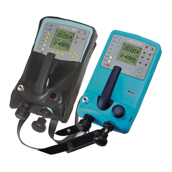
Portable Pressure Calibrator/Indicator
Do Not Print This Page
Pressure measurement
for research & industry
Druck Limited
Fir Tree Lane
Groby
Leicester LE6 0FH
England
Tel: 0116 231 7100
DPI 610/615 IS
User Manual
K249
K249 Issue No. 4
Advertisement
Table of Contents

Related Manuals for GE Druck DPI 610 IS


Summary of Contents for GE Druck DPI 610 IS
- Page 1 Pressure measurement for research & industry Druck Limited Fir Tree Lane Groby Leicester LE6 0FH England Tel: 0116 231 7100 DPI 610/615 IS Portable Pressure Calibrator/Indicator User Manual K249 © Druck Limited 2005 This document is the property of Druck Limited and may not, either in part or whole, be copied or otherwise reproduced, communicated in any way to third parties, nor stored in any data processing system, without the express written authority of Druck Limited.
- Page 2 Amendment Record Iss No Date C/N No Originator Typed Amendments 17/01/00 New specification 13/09/01 12016 No details recorded on amendment sheet 01/11/01 12946 No details recorded on amendment sheet 05/07/04 15727 Bob Lee Add copy of the Certificate of Conformity Approvals Engineering Marketing...
- Page 3 Print Instructions Print black on white, double sided as supplied on disk. Print on paper to 110 gsm, Silverblade matt art, wiro bind in 270 gsm covers. Size A5. THIS PUBLICATION IS PRINTED EXTERNALLY, THIS HARDCOPY IS NOT TO BE USED AS CAMERA COPY.
- Page 4 Page 4 of 68 K249 Issue No. 4 Do Not Print This Page...
- Page 5 GE Infrastructure Sensing Druck DPI 610/615 IS Portable Pressure Calibrator User manual - K249...
- Page 7 DPI 610/615 IS PORTABLE PRESSURE CALIBRATOR/INDICATOR USER GUIDE K249 Calibrator Version Indicator Version Hydraulic Actuator Version DPI 610/615 IS Portable Pressure Calibrator K249 Issue No. 4...
- Page 8 WARNING Before operating this instrument , read the safety instructions! © General Electric Company. All rights reserved. K249 Issue No. 4...
- Page 9 K249 Issue No. 4...
- Page 10 Safety The manufacturer has designed this equipment to be safe when operated using the procedures detailed in this manual. Do not use this equipment for any other purpose than that stated. This publication contains operating and safety instructions that must be followed to ensure safe operation and to maintain the equipment in a safe condition.
- Page 11 Specification Pressure Ranges (Internal Transducers) Safe working pressure 20 bar range 1.75 x full-scale 350 bar range 1.2 x full-scale 400 bar range 1.5 x full-scale All other ranges 2 x full-scale Accuracy Combined non-linearity, hysteresis and repeatability ±70 mbar range 0.05% F.S.
-
Page 12: Table Of Contents
CONTENTS Introduction General Description of Procedures Using the Guide Summary of Functions OPERATOR CONTROLS DISPLAY HARD KEY FUNCTIONS SOFT KEYS CURSOR KEYS ELECTRICAL CONNECTIONS Getting Started Fitting Batteries Switching On Change Pressure Units Voltage and Current Measurements Typical Calibration Set-up (Pressure to Voltage) Zero Display Reading Task Selection Task Key... - Page 13 CONTENTS (contd.) Advanced Task General Select Input Ambient Temperature Measurement Process Functions Tare Process Function Min/Max Process Function Filter Process Function Flow Function % Span Select Output Electrical Outputs (Loop Power) mA Step mA Ramp mA Value Task Set-up/Removal Define New Task Clear Task Memory Operations Saving Display (Snapshot) or Datalog...
- Page 14 CONTENTS (contd.) Using Set-up General Store Mode Contrast Settings - Select Set-up Option Units Def ine Special Units Language RS232 Powerdown Calibration Date and Time (Real Time Clock) Date Format Set Date Set T ime Calibration General Calibration Check Calibration Adjustment General Procedures Using The Calibration Menu Temperature...
-
Page 15: Introduction General
INTRODUCTION Summary of Functions General The DPI 610 IS and DPI 615 IS intrinsically safe instruments measure and display pneumatic and hydraulic pressure applied to the test port . Pressure measurement can be absolute, gauge and sealed gauge and in ranges from 2.5 mbar to 700 bar. -
Page 16: Using The Guide
INTRODUCTION Summary of Functions Using This Guide The following key symbols are used in the procedure diagrams which follow Shaded cursor keys indicate that a combination of these four keys, Up, Down, Left and Right should be used to (e.g.) enter an alpha numeric value or to select a function. -
Page 17: Operator Controls
INTRODUCTION Summary of Functions OPERATOR CONTROLS (Figure 1) These divide into two groups, the operator/display controls (shown in Figure 1) and the pressure/vacuum generation components (shown in Figure 2). The operator controls and a typical display, common to all instrument versions, is shown below. Figure 1 - DPI 610/615 Key-pad DISPLAY The display section of the instrument basically divides into four distinct sections. -
Page 18: Hard Key Functions
INTRODUCTION Summary of Functions HARD KEY FUNCTIONS (Fig. 1) s ’ t i l e . y r i l a a l i , e l . e l s ’ t s ’ t y l l l l a s l l . -
Page 19: Soft Keys
INTRODUCTION Summary of Functions SOFT KEYS (Fig. 1) Three soft keys, designated F1, EXIT and F2, are situated immediately below the display as shown below. These keys have their function allocated by the instrument software which is indicated in the bottom of the display (Voltage for F1 and Units for F2 in this example). -
Page 20: Electrical Connections
INTRODUCTION Summary of Functions ELECTRICAL CONNECTIONS Figure 3 - Electrical System Connections Measurement inputs and Source Outputs are made via the control panel sockets as shown below. Input Window max 30V DPI 615 IS CAT II TASK: BASIC Electrical Measurement Input Sockets INPUTS VOLTAGE... -
Page 21: Getting Started
Getting Started Fitting Batteries l a i l l e l l e WARNING: BATTERIES MUST ONLY BE FITTED IN A SAFE AREA. USE ONLY THE BATTERIES SPECIFIED IN THE TABLE. Caution: Old batteries can leak and cause corrosion. Never leave discharged batteries in the instrument. -
Page 22: Change Pressure Units
Getting Started Change Pressure Units To change the pressure units proceed as follows. If the four units displayed are not the units required, press TASK and select any task, other than BASIC, press SETUP and proceed as detailed on page 36. To return to BASIC mode, press TASK and select BASIC. -
Page 23: Typical Calibration Setup (Pressure To Voltage)
Getting Started Typical Calibration Setup (Pressure to Voltage) Connect a device under test to the instrument as shown below. SAFE Ext Press. Source (Indicator Only) SUPPLY BARRIER SAFE Pressure Regulator Max 30V CAT II DPI 615 IS TASK: BASIC VOLTAGE PRESSURE INT PRESSURE CURRENT... -
Page 24: Task Selection
Task Selection Task Key The TASK key is used to set up the instrument for a number of specific types of test. There are two modes BASIC and ADVANCED and nine other specific types of test which automatically configure the instrument on selection from the TASK menu. -
Page 25: Cal Mode
Task Selection Cal Mode (DPI 615 versions only) Cal mode, which is available in tasks P-I, P-P, P-V, P-P, P-DISPLAY and P-SWITCH, provides a method of setting up test parameters manually. Downloaded test procedures can also automatically set up and turn on the Cal Mode function. The method of turning on and setting up Cal Mode is shown below for a P-I task. -
Page 26: Taking Measurements
Taking Measurements Pressure Transmitter (P-I) Task Select the P-I task from the task menu and connect the Unit Under Test (UUT) to the calibrator as shown below. SAFE Ext Press. Source (Indicator Only) SUPPLY BARRIER SAFE max 30V Pressure DPI 615 IS Regulator TASK : P-I SNAPSHOT MODE... -
Page 27: Pressure Converter (P-P) Task
Taking Measurements Pressure Converter (Pressure to Pressure) Task Select the P-P task from the task menu and connect the Unit Under Test (UUT) to the calibrator as shown below. Testing a converter requires one pressure to be applied to the unit under test (UUT) and another (converter output) to be measured. -
Page 28: Current To Pressure Converter (I-P) Task
Taking Measurements Current to Pressure Converter (I-P) Task External SAFE Pressure Supply SUPPLY BARRIER SAFE max 30V DPI 615 IS TASK : I-P SNAPSHOT MODE PRESSURE INT OUTPUT NEW VALUE CURRENT • Use the Up and Down cursor keys to adjust the loop current to the required value. -
Page 29: Pressure To Display (P-Display) Task
Taking Measurements Pressure to Display (P-DISPLAY) Task P-Display is a special application of Datalog. To use this mode, select Datalog from the Store Mode menu as detailed on Page 36. Connect the device under test to the instrument as shown below and, if required, turn on and set-up Cal Mode (see page 11). -
Page 30: Leak Tests (Leak Test) Task
Taking Measurements Leak Test (LEAK TEST) Task External Pressure Source (Indicator Only) EXTERNAL SYSTEM Pressure Regulator max 30V DPI 615 IS TASK : LEAK TEST SNAPSHOT MODE PRESSURE INT WAIT secs DURATION secs START PRESS STOP PRESS PRESS CHANGE LEAK RATE bar/m CHANGE VALUE... -
Page 31: Transmitter Simulator (Tx Sim) Task
Taking Measurements Transmitter Simulator (TX SIM) Task When used with an external voltage source (see Page 24), provides a current output proportional to the calibrator’s measured output pressure (indicated pressure on indicator only version). Select task TX SIM. Press EXIT to skip set-up screen if parameters are correct. -
Page 32: Relief Valve Test (Rel Valve) Task
Taking Measurements Relief Valve Test (REL VALVE) Task To carry out a relief valve test , press TASK and select REL VALVE. Connect the output pressure port of the instrument to an external system as shown below. External Pressure Source (Indicator Only) Pressure Regulator... -
Page 33: Advanced Task
Advanced Task Select Input General Advanced task allows the user to configure the instrument to monitor one of a number of different input measurands (Inputs) and outputs (Sources). Additionally, five process functions, Tare, Max/Min, Filter, Flow and % Span can be applied to the input functions. -
Page 34: Process Functions
Advanced Task Process Functions Process Functions If required, the following process functions are available on the Measurand (INPUT) display but only in ADVANCED task. If the instrument is in any other mode i.e. BASIC or any other task mode, the input and output displays must first be configured in ADVANCED task. -
Page 35: Tare Process Function
Advanced Task Process Functions • Tare Process Function To set-up a Tare function, enable TARE from the process menu and press F1 to enter the Tare SETTINGS functions. Disable TARE by entering process menu and turning the function OFF. Note: Last TARE setting is retained and will be applied when function is next enabled. -
Page 36: Min/Max Process Function
Advanced Task Process Functions Min/Max Process Function • To set-up an input display to show min/max and present measurand reading, enable MIN/MAX from the process menu and press F1 (SETTINGS) to provide RESET function. The display is now reconfigured to show the max/min values as follows (e.g.), Reset Max/Min display at any time by pressing the F1 key. -
Page 37: Flow Function
Advanced Task Process Functions Flow Function • To apply the flow function to a selected measurand, enable FLOW from the process menu and press ENTER. The square root symbol is displayed beside the measurand to indicate that the FLOW function is active (e.g.) To cancel FLOW, press INPUT and turn function OFF at the process menu. -
Page 38: Select Output
Advanced Task Select Output Select Output To select an output channel for display, select ADVANCED mode from the Task menu and proceed as follows. If a channel has a range of units available, a UNITS soft box (actioned by the F2 function key), will be also be written to the display. The following procedure shows the method of output channel selection. -
Page 39: Ma Step
Advanced Task Select Output mA Step To select one of the electrical output programs, press the OUTPUT key and proceed as follows (e.g.), On selection of (e.g.) Linear, the output display window changes to show the selected program of output currents (e.g.), •... -
Page 40: Ma Ramp
Advanced Task Select Output mA Ramp Press the OUTPUT key and select mA Ramp in a similar manner to that shown above. • Define ramp required by entering START and END current values as shown below (e.g.), • Connect an external power source as shown on Page 24. •... -
Page 41: Ma Value
Advanced Task Select Output mA Value Press the OUTPUT key and select mA Value from the Output menu. The procedure is shown below (e.g.), • Connect an external power source as shown on Page 24. • Use Up and Down cursor keys to adjust output current level. -
Page 42: Task Set-Up/Removal
Advanced Task Task Setup/Removal Define New Task To define a new task, proceed as follows. • Select ADVANCED from TASK menu. • Using the INPUT key, select the required measurand as the input display and set-up any process functions required. •... -
Page 43: Memory Operations
Memory Operations Store Saving Display (Snapshot) or Datalog Memory operations depend upon how Store mode has been set-up. Three options are available None, Snapshot and Datalog. Refer to SETUP for details. Store Operations (Screen Snapshots) To store any display (menu displays excepted), press the STORE key. This saves the current display to the next available location. -
Page 44: Datalog Operations
Memory Operations Datalog Datalog Operations Datalog is a special application of store mode which enables the calibrator to either automatically log displays at preset time intervals or to manually log a display on operation of the STORE key. Logged data is written to a user specified file. -
Page 45: Recall Datalog Files
Memory Operations Datalog Recall Datalog Files To recall a datalog file to the display, make sure that DATALOG is selected from the SETUP menu and proceed as follows (e.g.), Datalog files can be displayed either as text (stored screens) or in graphical form. To display as text , proceed as follows from the File Summary menu. -
Page 46: Uploading Datalog Files
Memory Operations Datalog Uploading Datalog Files WARNING THE RS232 INTERFACE MUST ONLY BE USED IN A SAFE AREA Connect the RS232 socket of the instrument into either the COM1 or COM2 port of the PC. Ensure that the RS232 parameters at the PC end match those of the instrument. -
Page 47: Downloading Procedure Files
Memory Operations Datalog Downloading Procedure Files (DPI 615 versions only) WARNING THE RS232 INTERFACE MUST ONLY BE USED IN A SAFE AREA Complete test procedures may be downloaded from a PC to the DPI 615 instrument via the RS232 port. A procedure consists of a number of Druck Universal Command Interface (DUCI) commands which are usually assembled by a linking management software application (such as the Druck Intecal_W). -
Page 48: Running Procedure Files
Memory Operations Datalog Running Procedure Files (DPI 615 versions only) To run a procedure, make sure that the DPI 615 is set to the Datalog mode (see page 36), and proceed as follows. After selecting F1, proceed by entering the User ID and Serial Number and then select F1 (Continue) and follow the on-screen procedural instructions (e.g.), When the test procedure for a given UUT has been completed, the result of running the first test is stored as an AS FOUND file. -
Page 49: Recalling Data Files
Memory Operations Datalog Recalling Data Files Data or results files generated by running procedures are stored in the instrument’s datalog directory. To recall a data file to the display, make sure that DATALOG is selected from the SETUP menu and proceed as follows (e.g.), Use the cursor keys to select either the AS FOUND option or the AS LEFT option for display. -
Page 50: Using Setup
Using Setup General SETUP mode is available in all modes except BASIC. It permits the set-up of the following instrument parameters. • Store Mode - None, Snapshot, Datalog. • Contrast. • Instrument Settings - Units, Language, RS232 parameters, Powerdown, and Calibration Routines (Refer to page 40 for Calibration details). - Page 51 Using Setup Units Select (pressure) Units from the SETTINGS menu and proceed as follows. Define Special Units Select (pressure) Units from the SETTINGS menu, and select Special Units and proceed as follows. Language Select the LANGUAGE version required from the Settings menu and proceed as follows.
- Page 52 Using Setup RS232 Select RS232 from the SETTINGS Menu and proceed as follows. Note: Use of the RS232 communications interface is only permitted in a SAFE area. The settings shown above are the default settings. Powerdown Select Powerdown from the SETUP menu and proceed as follows. If TIMER mode is selected, following a period of inactivity, the instrument will automatically power off after the preset TIMER period.
- Page 53 Using Setup Date and Time (Real Time clock) Date Format To set-up the real time clock, select DATE & TIME from the SETUP menu and, using the right arrow key, set-up the required date format as shown below (e.g.), Set Date Select DATE from the DATE &...
-
Page 54: Calibration
Calibration General The instrument is supplied by the manufacturer, complete with calibration certificate(s). A re-calibration interval of 12 months is recommended. The actual re-calibration interval will depend upon the total measurement uncertainty which is acceptable for a particular application. The DPI 615 are very precise measuring instruments and the test equipment and conditions of test must be suitable for the type of work. -
Page 55: General Procedures
Calibration General Procedures The following general hints are provided as a guide to calibration procedures. Full calibration procedures are described in publication number K235. Use high quality Repeatable and Linear pressure sources and allow adequate stabilization time before calibration (minimum 1 hour). Conduct the calibration in a temperature and preferably, humidity controlled environment. -
Page 56: Temperature
Calibration Temperature • Precision Temperature Meter. On completion of calibration routines, exit the calibration mode by pressing the EXIT function key. Change PIN Number To change the PIN number, select CHANGE PIN from the calibration menu and proceed as follows. Note that to set and verify a new PIN number, the new PIN number must be entered twice. -
Page 57: Hydraulic Calibrator Version
HYDRAULIC CALIBRATOR VERSION K249 Issue No. 4... - Page 58 This page is intentionally blank K249 Issue No. 4...
-
Page 59: Introduction
HYDRAULIC CALIBRATOR VERSION Operation Introduction These versions of the DPI 610 IS and DPI 615 IS provide manual generation of hydraulic pressure and consist of a screw-press with a priming pump and priming isolation valve as shown below. The bleed pipe connections are also shown in Figure A1. -
Page 60: Safety Instructions
HYDRAULIC CALIBRATOR VERSION Operation Safety Instructions WARNING HYDRAULIC FLUID IS INJURIOUS. OBSERVE RELEVANT HEALTH AND SAFETY PRECAUTIONS. USE APPROPRIATE PROTECTIVE BARRIERS AND EYE PROTECTOR. BEFORE APPLYING PRESSURE, EXAMINE ALL FITTINGS AND EQUIPMENT FOR DAMAGE AND ENSURE THAT ALL EQUIPMENT IS TO THE CORRECT PRESSURE RATING. -
Page 61: Bleeding The System
HYDRAULIC CALIBRATOR VERSION Operation Figure A2 - Priming/Test Set-up Bleeding the System Before any measurements can be made, the hydraulic system needs to be primed and bled free of air. During the following operations, prepare for fluid spillage and provide a suitable receptacle for collecting the spillage. Prepare for use as detailed on page 46. -
Page 62: Draining The Hydraulic Fluid
HYDRAULIC CALIBRATOR VERSION Operation Continue use of the priming pump until only hydraulic fluid and no air is expelled from the bleed point . Close the bleed point when the priming pump is at the bottom of its stroke (fully pushed in) and slowly wind out the screw-press to its fullest extent to draw in further hydraulic fluid (approx. -
Page 63: Flushing, Replenishing Or Changing The Hydraulic Fluid
HYDRAULIC CALIBRATOR VERSION Operation Flushing - Replenishing or Changing the Hydraulic Fluid If necessary, to remove any contaminants, flush out the hydraulic system as follows. Connect a priming hose assembly to the fluid inlet port and the pressure port as shown below. Figure A3 - DPI 610/615 IS HC - Flushing/Filling Connections Fill the priming fluid container with fresh hydraulic fluid of the required type. - Page 64 HYDRAULIC CALIBRATOR VERSION Operation Notes K249 Issue No. 4...
-
Page 65: Appendix 1 - Datalog File Example
Appendix 1 DATALOG FILE EXAMPLE K249 Issue No. 4... - Page 66 This page intentionally blank K249 Issue No. 4...
- Page 67 Appendix 1 Typical Uploaded Datalog File (DPI 610 IS) The following gives details of a typical data file upload. FILENAME: TEST 5 DATE: 05/11/1999 TIME: 15:58 TRIGGER: KEYPRESS AMBIENT TEMP : 24.1 C NO. OF POINTS RECORD TYPE CURRENT PRESSURE INT bar 3.902 0.008 -0.65 %span 05/11/1999...
- Page 68 Typical Uploaded Procedure Data File (DPI 615 IS) The following gives details of a typical data file upload. FILENAME: TEST 6 DATE: 05/11/1999 TIME: 15:58 TRIGGER: KEYPRESS AMBIENT TEMP : 24.1 C NO. OF POINTS RECORD TYPE CURRENT PRESSURE INT bar 3.902 0.008 -0.65 %span PASS...