
Related Manuals for Extreme Networks ExtremeSwitching X435 Series


Summary of Contents for Extreme Networks ExtremeSwitching X435 Series
- Page 1 ExtremeSwitching Hardware Installation Guide for Switches Using ExtremeXOS Version 30 121248-05 Rev. AG December 2020...
- Page 2 Copyright © 2020 Extreme Networks, Inc. All rights reserved. Legal Notice Extreme Networks, Inc. reserves the right to make changes in specifications and other information contained in this document and its website without prior notice. The reader should in all cases consult representatives of Extreme Networks to determine whether any such changes have been made.
-
Page 3: Table Of Contents
Subscribe to Service Notifications......................17 Documentation and Training..........................17 ExtremeSwitching Switches..................... 19 Overview of the Switches............................20 Combination Ports and Failover........................20 Port Partitioning..............................21 ExtremeSwitching X435 Series Switches...................... 22 Management................................ 22 Cooling................................... 22 Power Supplies..............................23 Operating Temperatures..........................23 ExtremeSwitching X435-8T-4S Switch Features................23 ExtremeSwitching X435-8P-4S Switch Features................24... - Page 4 Table of Contents ExtremeSwitching X440-G2 Series Switch LEDs................45 ExtremeSwitching X450-G2 Series Switches....................47 ExtremeSwitching X450-G2-24t-GE4 Switch Ports and Slots..........48 ExtremeSwitching X450-G2-24t-10GE4 Switch Ports and Slots..........49 ExtremeSwitching X450-G2-48t-GE4 Switch Ports and Slots..........50 ExtremeSwitching X450-G2-48t-10GE4 Switch Ports and Slots..........51 ExtremeSwitching X450-G2-24p-GE4 Switch Ports and Slots..........
- Page 5 Table of Contents ExtremeSwitching X590 Series Switch LEDs..................87 ExtremeSwitching X620 Series Switches......................89 X620 Stacking..............................89 Additional X620 Features..........................89 ExtremeSwitching X620-8t-2x Switch Ports and Slots..............90 ExtremeSwitching X620-10x Switch Ports and Slots...............91 ExtremeSwitching X620-16t Switch Ports and Slots...............92 ExtremeSwitching X620-16x Switch Ports and Slots..............93 ExtremeSwitching X620-16p Switch Ports and Slots..............
- Page 6 Table of Contents Summit 770 W AC Power Supplies......................136 Summit 1100 W AC Power Supplies....................... 136 Summit 1100 W DC Power Supplies....................... 137 ExtremeSwitching 2000 W AC Power Supply................. 138 Displaying the Status of Installed Power Supplies...................138 Expansion Modules......................139 V300 Virtual Port Extender..........................
- Page 7 Connecting the Switches to Form the Stack Ring................213 Connecting Stacking Cables........................218 Connecting Your Stack to the Management Network..............220 Installing Your Extreme Networks Switch..............221 Safety Considerations for Installing Switches................... 222 Pre-installation Requirements........................... 222 Attaching the Switch to a Rack or Cabinet....................223 Installing Optional Components........................227...
- Page 8 Table of Contents Logging in for the First Time........................260 Configuring the Switch's IP Address for the Management VLAN...........261 Configuring ExtremeXOS on the Switch.....................262 Installing External Power Supplies................263 Safety Considerations for Installing Power Supplies................263 Pre-installation Requirements...........................264 Installing an EPS-C2 Power Supply........................264 Installing an EPS-C2 Chassis........................265 Installing a Summit 750 W AC Power Supply into the EPS-C2..........267 Connecting Redundant Power Cables for the EPS-C2 Chassis..........268...
- Page 9 Table of Contents Installing an LRM/MACsec Adapter Horizontally................317 Installing LRM/MACsec Adapters in the Five-Slot Bracket............318 Installing an LRM/MACsec Adapter Vertically.................. 319 Connecting the LRM/MACsec Adapter to the Host Switch and to Power......319 Installing a Half-Duplex to Full-Duplex Converter.................. 320 Installing Half-Duplex to Full-Duplex Converters in a 3-Slot Modular Shelf......320 Mounting a Half-Duplex to Full-Duplex Converter on a Flat Surface........320 Mounting a Half-Duplex to Full-Duplex Converter on a Wall.............
- Page 10 Removing an AC Power Supply........................374 Removing a DC Power Supply..........................375 Removing a Switch from a Rack........................376 Technical Specifications....................378 ExtremeSwitching X435 Series Switches Technical Specifications..........379 Power Options..............................381 Standards and Environmental Data...................... 383 ExtremeSwitching X440-G2 Series Switches Technical Specifications........385 Physical Dimensions............................385...
- Page 11 Table of Contents Fan Speed................................421 Acoustic Sound..............................421 Power Specifications............................ 422 Power Supplies..............................422 CPU, Memory..............................423 Environmental Data............................423 Scaling and Performance........................... 424 Safety Standards............................424 EMI/EMC Standards............................424 Telecom Standards............................425 IEEE 802.3 Media Access Standards....................425 Summit X670-G2 Series Switches Technical Specifications..............425 Power Options..............................
- Page 12 Table of Contents Summit 350 W Power Supplies Technical Specifications..............455 Summit 350 W AC Power Supply (10953, 10954)................. 455 Summit 550 W Power Supplies Technical Specifications..............456 Summit 715 W Power Supplies Technical Specifications..............457 750 W Power Supplies Technical Specifications..................458 750 W Power Supplies Technical Specifications..................459 Summit 770 W Power Supplies Technical Specifications..............
- Page 13 Table of Contents Index..........................486 ExtremeSwitching Hardware Installation Guide xiii...
-
Page 14: Preface
ExtremeXOS 30.7 Command Reference Guide information about configuring ExtremeSwitching switches. Note If the information in an installation note or release note shipped with your Extreme Networks equipment differs from the information in this guide, follow the installation or release note. Conventions This section discusses the conventions used in this guide. -
Page 15: Text Conventions
Preface Text Conventions Text Conventions Unless otherwise noted, information in this document applies to all supported environments for the products in question. Exceptions, like command keywords associated with a specific software version, are identified in the text. When a feature, function, or operation pertains to a specific hardware product, the product name is used. -
Page 16: Terminology
Providing Feedback The Information Development team at Extreme Networks has made every effort to ensure the accuracy and completeness of this document. We are always striving to improve our documentation and help you work better, so we want to hear from you. -
Page 17: Subscribe To Service Notifications
The Hub A forum for Extreme Networks customers to connect with one another, answer questions, and share ideas and feedback. This community is monitored by Extreme Networks employees, but is not intended to replace specific guidance from GTAC. - Page 18 Documentation and Training Preface Extreme Networks offers product training courses, both online and in person, as well as specialized certifications. For details, visit www.extremenetworks.com/education/. ExtremeSwitching Hardware Installation Guide...
-
Page 19: Extremeswitching Switches
ExtremeSwitching Switches Overview of the Switches on page 20 ExtremeSwitching X435 Series Switches on page 22 ExtremeSwitching X440-G2 Series Switches on page 29 ExtremeSwitching X450-G2 Series Switches on page 47 ExtremeSwitching X460-G2 Series Switches on page 58 ExtremeSwitching X465 Series Switches... -
Page 20: Overview Of The Switches
The copper port operates as an autonegotiating 10/100/1000BASE-T port. The optical port allows Gigabit Ethernet uplink connections through Extreme Networks small form factor pluggable (SFP) interface modules. See the individual switch descriptions for the port numbers of the combination ports on each switch model. -
Page 21: Port Partitioning
ExtremeSwitching Switches Port Partitioning connect copper ports x and y on a switch, and then insert SFPs into ports x and y, the switch assigns the copper ports as active ports and the fiber ports as redundant ports. Hardware identifies when a link is lost and responds by swapping the primary and redundant ports to maintain stability. -
Page 22: Extremeswitching X435 Series Switches
ExtremeSwitching X435 Series Switches ExtremeSwitching Switches Table 4: QSFP28 and QSFP+ Port Partitioning (continued) Switch model Port bandwidth Port partitions X870 (all models) 100 Gb One 100 Gb port with one of the following: QSFP28 and QSFP+ • Two 50 Gb ports •... -
Page 23: Power Supplies
One USB A port • LEDs to indicate port status and switch operating conditions For a description of the LEDs and their operation, see ExtremeSwitching X435 Series Switch LEDs page 28 Figure 1: X435-8T-4S Switch Front Panel 1 = System LEDs 3 = RJ-45 console port 5 = 1/2.5G SFP ports*... -
Page 24: Extremeswitching X435-8P-4S Switch Features
One USB A port • LEDs to indicate port status and switch operating conditions For a description of the LEDs and their operation, see ExtremeSwitching X435 Series Switch LEDs page 28 Figure 3: X435-8P-4S Front Panel 1 = System LEDs 3 = RJ-45 console port 5 = 1/2.5G SFP ports*... -
Page 25: Extremeswitching X435-8P-2T-W Switch Features
One USB A port • LEDs to indicate port status and switch operating conditions For a description of the LEDs and their operation, see ExtremeSwitching X435 Series Switch LEDs page 28 Figure 5: X435-8P-2T-W Front Panel 1 = System LEDs 3 = RJ-45 console port 5 = 10/100/1000BASE-T 802.3bt ports... -
Page 26: Extremeswitching X435-24T-4S Switch Features
One USB A port • LEDs to indicate port status and switch operating conditions For a description of the LEDs and their operation, see ExtremeSwitching X435 Series Switch LEDs page 28 Figure 7: X435-24T-4S Front Panel 1 = System LEDs 3 = RJ-45 console and management ports 5 = 1/2.5G SFP ports*... -
Page 27: Extremeswitching X435-24P-4S Switch Features
One USB A port • LEDs to indicate port status and switch operating conditions For a description of the LEDs and their operation, see ExtremeSwitching X435 Series Switch LEDs page 28. Figure 9: X435-24P-4S Front Panel 1 = System LEDs 3 = RJ-45 console and management ports 5 = 1/2.5G SFP ports*... -
Page 28: Extremeswitching X435 Series Switch Leds
ExtremeSwitching X435 Series Switch LEDs ExtremeSwitching Switches Figure 10: X435-24P-4S Rear Panel ExtremeSwitching X435 Series Switch LEDs The following figures illustrate the X435 front panel LEDs: Figure 11: X435-8T/8P LEDs Figure 12: X435-8P-2T-W LEDs Figure 13: X435-24T/24P LEDs The X435 front panel LEDs behave as follows:... -
Page 29: Extremeswitching X440-G2 Series Switches
ExtremeSwitching Switches ExtremeSwitching X440-G2 Series Switches Table 5: X435 System LEDs (continued) Color/State Port State System Blinking Green System Normal System off Table 6: X435 Port LEDs Color/State Port State Solid green Link is OK Blinking Green Traffic activity Solid Amber PoE and link is up Blinking amber Link is OK and transmitting packets;... -
Page 30: Security
Security ExtremeSwitching Switches The ExtremeSwitching X440-G2 series switches include the following base models: • ExtremeSwitching X440-G2-12t-10GE4 switch • ExtremeSwitching X440-G2-12p-10GE4 switch • ExtremeSwitching X440-G2-24t-10GE4 switch • ExtremeSwitching X440-G2-24x-10GE4 switch • ExtremeSwitching X440-G2-24p-10GE4 switch • ExtremeSwitching X440-G2-48t-10GE4 switch • ExtremeSwitching X440-G2-48p-10GE4 switch •... -
Page 31: Operating Temperatures
ExtremeSwitching Switches Operating Temperatures implementing a stacking solution. For a list of X440-G2 ports that can be used with SummitStack-V, see X440-G2 Stacking on page 195. On X440-G2 switches, SummitStack-V is compatible with X450-G2 and X460-G2 switches with 10 Gb uplinks and with X620, and X670-G2 switches running the same version of ExtremeXOS. -
Page 32: Extremeswitching X440-G2-12T-10Ge4 Switch Ports And Slots
ExtremeSwitching X440-G2-12t-10GE4 Switch Ports and Slots ExtremeSwitching Switches All X440-G2 switches support external redundant power options. For details, refer to Table 38 on page 120. Note See the ExtremeXOS 30.7 User Guide and the ExtremeXOS 30.7 Command Reference Guide for feature-specific information about the switches and for information regarding switch configuration. -
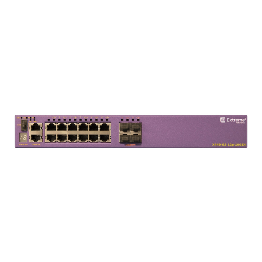
Page 33: Extremeswitching X440-G2-12P-10Ge4 Switch Ports And Slots
ExtremeSwitching X440-G2-12p-10GE4 Switch Ports ExtremeSwitching Switches and Slots Figure 15: ExtremeSwitching X440-G2-12t-10GE4 Rear Panel 1 = Redundant power input 3 = AC power input socket 2 = Grounding lug ExtremeSwitching X440-G2-12p-10GE4 Switch Ports and Slots The ExtremeSwitching X440-G2-12p-10GE4 switch ports and slots include: •... -
Page 34: Extremeswitching X440-G2-24T-10Ge4 Switch Ports And Slots
ExtremeSwitching X440-G2-24t-10GE4 Switch Ports and Slots ExtremeSwitching Switches 1 = Stack number indicator 4 = 10/100/1000BASE-T copper ports 2 = Console port/Ethernet management port 5 = SFP Ports upgradeable to 10GBASE-X 3 = USB port (active with ExtremeXOS version 22.2 or later) Figure 17: ExtremeSwitching X440-G2-12p-10GE4 Rear Panel 1 = Redundant power input 3 = AC power input socket... -
Page 35: Extremeswitching X440-G2-24X-10Ge4 Switch Ports And Slots
ExtremeSwitching X440-G2-24x-10GE4 Switch Ports ExtremeSwitching Switches and Slots Figure 18: ExtremeSwitching X440-G2-24t-10GE4 Front Panel 1 = Stack number indicator 4 = 10/100/1000BASE-T copper ports 2 = Console port/Ethernet management port 5 = 1000BASE-X SFP combination ports 3 = USB port (active with ExtremeXOS version 22.2 or later) Figure 19: ExtremeSwitching X440-G2-24t-10GE4 Rear Panel 1 = Grounding lug 3 = Redundant power input... -
Page 36: Extremeswitching X440-G2-24P-10Ge4 Switch Ports And Slots
ExtremeSwitching X440-G2-24p-10GE4 Switch Ports and Slots ExtremeSwitching Switches • One front panel USB 2.0 port, operational on switches running ExtremeXOS version 22.2 or later. • One rear redundant power supply connector. Figure 20: ExtremeSwitching X440-G2-24x-10GE4 Front Panel 1 = Stack number indicator 4 = 1GBASE-X SFP ports 2 = Console port/Ethernet management port 5 = 10/100/1000BASE-T combination ports... -
Page 37: Extremeswitching X440-G2-48T-10Ge4 Switch Ports And Slots
ExtremeSwitching X440-G2-48t-10GE4 Switch Ports ExtremeSwitching Switches and Slots • One front panel USB 2.0 port, operational on switches running ExtremeXOS version 22.2 or later. • One rear redundant power supply connector. Figure 22: ExtremeSwitching X440-G2-24p-10GE4 Front Panel 1 = Stack number indicator 4 = 10/100/1000BASE-T copper ports 2 = Console port/Ethernet management port 5 = 1GBASE-X SFP combination ports... -
Page 38: Extremeswitching X440-G2-48P-10Ge4 Switch Ports And Slots
ExtremeSwitching X440-G2-48p-10GE4 Switch Ports and Slots ExtremeSwitching Switches • Two 1GbE copper combination ports that can be upgraded to 10Gb Ethernet. • Ethernet management port (10/100/1000BASE-T). • Serial console port implemented as an RJ45 connector used to connect a terminal and perform local management. - Page 39 ExtremeSwitching X440-G2-48p-10GE4 Switch Ports ExtremeSwitching Switches and Slots • Four unpopulated rear panel 1GBASE-X SFP+ ports that can be used as either 1Gb ports or 10Gb ports, where the 10Gb configuration requires an upgrade through additional licensing.. Alternately, you can convert two of the ports to stacking ports using the enable stacking- support command.
-
Page 40: Extremeswitching X440-G2-24T-10Ge4-Dc Switch Ports And Slots
ExtremeSwitching X440-G2-24t-10GE4-DC Switch Ports and Slots ExtremeSwitching Switches ExtremeSwitching X440-G2-24t-10GE4-DC Switch Ports and Slots The ExtremeSwitching X440-G2-24t-10GE4-DC switch ports and slots include: • 24 front panel ports of 10/100/1000BASE-T (RJ45). Both half-duplex and full-duplex communication are supported on ports 1 through 16. Ports 17 through 24 are full-duplex only. •... -
Page 41: Extremeswitching X440-G2-48T-10Ge4-Dc Switch Ports And Slots
ExtremeSwitching X440-G2-48t-10GE4-DC Switch ExtremeSwitching Switches Ports and Slots 2 = SFP Ports upgradeable to 10GBASE-X 4 = DC power connector panel ExtremeSwitching X440-G2-48t-10GE4-DC Switch Ports and Slots The ExtremeSwitching X440-G2-48t-10GE4-DC switch ports and slots include: • 48 front panel ports of 10/100/1000BASE-T (RJ45). Both half-duplex and full-duplex communication are supported on ports 1 through 16 and 25 through 40. -
Page 42: Extremeswitching X440-G2-12T8Fx-Ge4 Switch Ports And Slots
ExtremeSwitching X440-G2-12t8fx-GE4 Switch Ports and Slots ExtremeSwitching Switches Figure 31: ExtremeSwitching X440-G2-48t-10GE4-DC Rear Panel 1 = SFP Ports upgradeable to 10GBASE-X 4 = DC power connector panel 2 = 1GBASE-T combination ports upgradeable to 10GBASE-T 5 = Grounding lug 3 = Redundant power input ExtremeSwitching X440-G2-12t8fx-GE4 Switch Ports and Slots The ExtremeSwitching X440-G2-12t8fx-GE4 switch ports and slots include: •... -
Page 43: Extremeswitching X440-G2-24Fx-Ge4 Switch Ports And Slots
ExtremeSwitching X440-G2-24fx-GE4 Switch Ports and ExtremeSwitching Switches Slots Figure 32: ExtremeSwitching X440-G2-12t8fx-GE4 Front Panel 1 = Stack number indicator 4 = 10/100/1000BASE-T ports 2 = Console port/Ethernet management port 5 = 1GBASE-X SFP ports 3 = USB port (active with ExtremeXOS version 22.2 or later) 6 = 100BASE-FX LC connectors Figure 33: ExtremeSwitching X440-G2-12t8fx-GE4 Rear Panel 1 = Redundant power input... -
Page 44: Extremeswitching X440-G2-24T-Ge4 Switch Ports And Slots
ExtremeSwitching X440-G2-24t-GE4 Switch Ports and Slots ExtremeSwitching Switches • Ethernet management port (10/100/1000BASE-T). • Serial console port implemented as an RJ45 connector used to connect a terminal and perform local management. • One front panel USB 2.0 port, operational on switches running ExtremeXOS version 22.2 or later. •... -
Page 45: Extremeswitching X440-G2 Series Switch Leds
ExtremeSwitching Switches ExtremeSwitching X440-G2 Series Switch LEDs • One front panel USB 2.0 port, operational on switches running ExtremeXOS version 22.2 or later. • One rear redundant power supply connector. The X440-G2 24t-GE4 switch supports an operating range from 0°C to 60°C. Figure 36: ExtremeSwitching X440-G2-24t-GE4 Front Panel 1 = Stack number indicator 3 = USB port (active with ExtremeXOS version 22.2 or later) - Page 46 ExtremeSwitching X440-G2 Series Switch LEDs ExtremeSwitching Switches Table 9: X440-G2 Front Panel LEDs Label or Type Color/State Meaning M (Management) Slow blinking green (1 Hz) Normal operation Fast blinking green (2 Hz) Power-on self test (POST) in progress Switch diagnostics are running Steady green POST passed: system is booting image Blinking amber...
-
Page 47: Extremeswitching X450-G2 Series Switches
ExtremeSwitching Switches ExtremeSwitching X450-G2 Series Switches Table 10: Additional Port LED Meanings for PoE Switches: X440-G2-12p-10GE4, X440-G2-24p-10GE4, and X440-G2-48p-10GE4 (continued) Label or Type Color/State Meaning All front panel ports Steady amber Link is OK; port is powered; no traffic Blinking green Link is OK and transmitting packets;... -
Page 48: Extremeswitching X450-G2-24T-Ge4 Switch Ports And Slots
ExtremeSwitching X450-G2-24t-GE4 Switch Ports and Slots ExtremeSwitching Switches Each base model supports front-to-back cooling only. Switch cooling is provided by a replaceable fan module. Note The fan module must be ordered separately. A serial console port on the front panel of the X450-G2 series switch allows you to connect a terminal and perform local management. -
Page 49: Extremeswitching X450-G2-24T-10Ge4 Switch Ports And Slots
ExtremeSwitching X450-G2-24t-10GE4 Switch Ports ExtremeSwitching Switches and Slots ACT LINK Summit ™ X450-G2-24t-GE4 CONSOLE STACK NO. GbE S FP Figure 38: X450-G2-24t-GE4 Front Panel 1 = Stack number indicator 4 = 10/100/1000BASE-T ports 2 = Console port/Ethernet management port 5 = SFP 1GBASE-X ports 3 = USB port SummitStack-V84 Redundant Power Input... -
Page 50: Extremeswitching X450-G2-48T-Ge4 Switch Ports And Slots
ExtremeSwitching X450-G2-48t-GE4 Switch Ports and Slots ExtremeSwitching Switches ACT LINK Summit ™ X450-G2-24t-10GE4 CONSOLE STACK NO. 10GbES FP+ Figure 40: X450-G2-24t-10GE4 Front Panel 1 = Stack number indicator 4 = 10/100/1000BASE-T ports 2 = Console port/Ethernet management port 5 = SFP+ 10GBASE-X ports 3 = USB port SummitStack-V84 Redundant Power Input... -
Page 51: Extremeswitching X450-G2-48T-10Ge4 Switch Ports And Slots
ExtremeSwitching X450-G2-48t-10GE4 Switch Ports ExtremeSwitching Switches and Slots ACT LINK STACK NO. CONSOLE Summit X450-G2-48t-GE4 ™ GbES FP Figure 42: X450-G2-48t-GE4 Front Panel 1 = Stack number indicator 4 = 10/100/1000BASE-T ports 2 = Console port/Ethernet management port 5 = SFP 1GBASE-X ports 3 = USB port SummitStack-V84 Redundant Power Input... -
Page 52: Extremeswitching X450-G2-24P-Ge4 Switch Ports And Slots
ExtremeSwitching X450-G2-24p-GE4 Switch Ports and Slots ExtremeSwitching Switches ACT LINK STACK NO. CONSOLE Summit ™ X450-G2-48t-10GE4 10GbES FP+ Figure 44: X450-G2-48t-10GE4 Front Panel 1 = Stack number indicator 4 = 10/100/1000BASE-T ports 2 = Console port/Ethernet management port 5 = SFP+ 10GBASE-X ports 3 = USB port SummitStack-V84 Redundant Power Input... -
Page 53: Extremeswitching X450-G2-24P-10Ge4 Switch Ports And Slots
ExtremeSwitching X450-G2-24p-10GE4 Switch Ports ExtremeSwitching Switches and Slots ACT LINK Summit ™ X450-G2-24p-GE4 STACK NO. CONSOLE GbES FP Figure 46: X450-G2-24p-GE4 Front Panel 1 = Stack number indicator 4 = PoE+ 10/100/1000BASE-T ports 2 = Console port/Ethernet management port 5 = SFP 1G ports 3 = USB port IN.OK OUT. -
Page 54: Extremeswitching X450-G2-48P-Ge4 Switch Ports And Slots
ExtremeSwitching X450-G2-48p-GE4 Switch Ports and Slots ExtremeSwitching Switches ACT LINK STACK NO. Figure 48: X450-G2-24p-10GE4 Front Panel 1 = Stack number indicator 4 = PoE+ 10/100/1000BASE-T ports 2 = Console port/Ethernet management port 5 = SFP+ 10GBASE-X ports 3 = USB port IN.OK OUT. -
Page 55: Extremeswitching X450-G2-48P-10Ge4 Switch Ports And Slots
ExtremeSwitching X450-G2-48p-10GE4 Switch Ports ExtremeSwitching Switches and Slots ACT LINK STACK NO. CONSOLE Summit ™ X450-G2-48p-GE4 GbES FP Figure 50: X450-G2-48p-GE4 Front Panel 1 = Stack number indicator 4 = PoE+ 10/100/1000BASE-T ports 2 = Console port/Ethernet management port 5 = SFP 1GBASE-X ports 3 = USB port IN.OK OUT. -
Page 56: Extremeswitching X450-G2 Series Switch Leds
ExtremeSwitching X450-G2 Series Switch LEDs ExtremeSwitching Switches ACT LINK STACK NO. CONSOLE Summit ™ X450-G2-48p-10GE4 10GbES FP+ Figure 52: X450-G2-48p-10GE4 Front Panel 1 = Stack number indicator 4 = PoE+ 10/100/1000BASE-T ports 2 = Console port/Ethernet management port 5 = SFP+ 10GBASE-X ports 3 = USB port IN.OK OUT. - Page 57 ExtremeSwitching Switches ExtremeSwitching X450-G2 Series Switch LEDs Table 12: X450-G2 Front Panel LEDs (continued) Label or Type Color/State Meaning Steady green Normal operation Blinking amber Failure No power P1, P2 (Power Supply) Steady green Normal operation Steady amber Power is attached, but no power is on Blinking amber Power failure No power attached...
-
Page 58: Extremeswitching X460-G2 Series Switches
ExtremeSwitching X460-G2 Series Switches ExtremeSwitching Switches ExtremeSwitching X460-G2 Series Switches The X460-G2 series switches provide 24 or 48 Ethernet ports that deliver high-density fast Ethernet or Gigabit Ethernet connectivity using fixed BASE-T and BASE-X ports. In addition, some models offer either 24 or 48 PoE+ ports. -
Page 59: Versatile Interface Module (Vim) Options For X460-G2 Series Switches
Versatile Interface Module (VIM) Options for X460-G2 ExtremeSwitching Switches Series Switches The following X460-G2 switch models require ExtremeXOS version 22.2.1 or later: • ExtremeSwitching X460-G2-24t-24ht-10GE4 • ExtremeSwitching X460-G2-24p-24hp-10GE4 • ExtremeSwitching X460-G2-16mp-32p-10GE4 All other X460-G2 switch models are compatible with ExtremeXOS version 15.6.1.4 or later, or version 21.1.1 or later. -
Page 60: Extremeswitching X460-G2-24T-10Ge4 Switch Ports And Slots
ExtremeSwitching X460-G2-24t-10GE4 Switch Ports and Slots ExtremeSwitching Switches • One front panel USB port. • Ethernet management port 1 x 10/100/1000BASE-T. • Serial console port implemented as an RJ45 connector used to connect a terminal and perform local management. • One rear panel VIM slot. -
Page 61: Extremeswitching X460-G2-24X-10Ge4 Switch Ports And Slots
ExtremeSwitching X460-G2-24x-10GE4 Switch Ports ExtremeSwitching Switches and Slots • Serial console port implemented as an RJ45 connector used to connect a terminal and perform local management. • One rear panel VIM slot. • One rear panel TM-CLK (clock) slot. • Rear dual PSU power slots with front-to-back or back-to-front airflow. -
Page 62: Extremeswitching X460-G2-24P-Ge4 Switch Ports And Slots
ExtremeSwitching X460-G2-24p-GE4 Switch Ports and Slots ExtremeSwitching Switches • Serial console port implemented as an RJ45 connector used to connect a terminal and perform local management. • One rear panel VIM slot. • One rear panel TM-CLK (clock) slot. • Rear dual PSU power slots with front-to-back or back-to-front airflow. -
Page 63: Extremeswitching X460-G2-24P-10Ge4 Switch Ports And Slots
ExtremeSwitching X460-G2-24p-10GE4 Switch Ports ExtremeSwitching Switches and Slots • One rear panel VIM slot. • One rear panel TM-CLK (clock) slot. • Rear dual PSU power slots with front-to-back or back-to-front airflow. • One rear slot for fan module with front-to-back or back-to-front airflow. P1 P2 ACT LINK X4 6 0 -G2 -2 4 p-GE4... -
Page 64: Extremeswitching X460-G2-48T-Ge4 Switch Ports And Slots
ExtremeSwitching X460-G2-48t-GE4 Switch Ports and Slots ExtremeSwitching Switches • One rear panel TM-CLK (clock) slot. • Rear dual PSU power slots with front-to-back or back-to-front airflow. • One rear slot for fan module with front-to-back or back-to-front airflow. P1 P2 ACT LINK X4 6 0 -G2 -2 4 p-10GE4 SYNC-E Input Ports... -
Page 65: Extremeswitching X460-G2-48T-10Ge4 Switch Ports And Slots
ExtremeSwitching X460-G2-48t-10GE4 Switch Ports ExtremeSwitching Switches and Slots P1 P2 ACT LINK X460-G2- 48t-GE4 X460-G2- 48t-GE4 SYNC-E Input Ports SYNC-E Input Ports SYNC-E Inputs 1 Gb E SFP Figure 64: X460-G2-48t-GE4 Front Panel 1 = Stack number indicator 4 = 10/100/1000BASE-T ports 2 = Console port/Ethernet management port 5 = SFP 1GBASE-X ports 3 = USB port... -
Page 66: Extremeswitching X460-G2-24T-24Ht-10Ge4 Switch Ports And Slots
ExtremeSwitching X460-G2-24t-24ht-10GE4 Switch Ports and Slots ExtremeSwitching Switches P1 P2 ACT LINK X460-G2- 48t-10GE4 X460-G2- 48t-10GE4 SYNC-E Input Ports SYNC-E Input Ports SYNC-E Inputs 1 0 Gb E SFP + Figure 66: X460-G2-48t-10GE4 Front Panel 1 = Stack number indicator 4 = 10/100/1000BASE-T ports 2 = Console port/Ethernet management port 5 = SFP+ 10GBASE-X ports... -
Page 67: Extremeswitching X460-G2-48X-10Ge4 Switch Ports And Slots
ExtremeSwitching X460-G2-48x-10GE4 Switch Ports ExtremeSwitching Switches and Slots Figure 68: X460-G2-24t-24ht-10GE4 Front Panel 1 = Stack number indicator 4 = 10/100/1000BASE-T ports 2 = Console port/Ethernet management port 5 = 10/100/1000BASE-T ports with half-duplex 3 = USB port 6 = SFP+ 10GBASE-X ports Figure 69: X460-G2-24t-24ht-10GE4 Rear Panel 1 = TM-CLK (clock) slot cover 4 = Blank power supply cover... -
Page 68: Summit X460-G2-48P-Ge4 Switch Ports And Slots
Summit X460-G2-48p-GE4 Switch Ports and Slots ExtremeSwitching Switches • Rear dual PSU power slots with front-to-back or back-to-front airflow. • One rear slot for fan module with front-to-back or back-to-front airflow. P1 P2 ACT LINK X4 6 0 -G2 -4 8 x -10GE4 1 0 Gb E SFP + All P o r t s S yn c h ro n o u s E t h e rn e t... -
Page 69: Extremeswitching X460-G2-48P-10Ge4 Switch Ports And Slots
ExtremeSwitching X460-G2-48p-10GE4 Switch Ports ExtremeSwitching Switches and Slots P1 P2 ACT LINK X4 6 0 -G2 -4 8 p-GE4 SYNC-E Input Ports SYNC-E Inputs 1 0 Gb E SFP + Figure 72: Summit X460-G2-48p-GE4 Front Panel 1 = USB port 4 = PoE+ 10/100/1000BASE-T ports 2 = Stack number indicator 5 = SFP 1GBASE-X ports... -
Page 70: Extremeswitching X460-G2-24P-24Hp-10Ge4 Switch Ports And Slots
ExtremeSwitching X460-G2-24p-24hp-10GE4 Switch Ports and Slots ExtremeSwitching Switches P1 P2 ACT LINK X4 6 0 -G2 -4 8 p-10GE4 SYNC-E Input Ports SYNC-E Inputs 1 0 Gb E SFP + Figure 74: X460-G2-48p-10GE4 Front Panel 1 = USB port 4 = PoE+ 10/100/1000BASE-T ports 2 = Stack number indicator 5 = SFP+ 10GBASE-X ports 3 = Console port/Ethernet management port... -
Page 71: Extremeswitching X460-G2-16Mp-32P-10Ge4 Switch Ports And Slots
ExtremeSwitching X460-G2-16mp-32p-10GE4 Switch ExtremeSwitching Switches Ports and Slots Figure 76: X460-G2-24p-24hp-10GE4 Front Panel 1 = Stack number indicator 4 = PoE+ 10/100/1000BASE-T ports 2 = Console port/Ethernet management port 5 = PoE+ 10/100/1000BASE-T ports with half-duplex 3 = USB port 6 = SFP+ 10GBASE-X ports Figure 77: X460-G2-24p-24hp-10GE4 Rear Panel 1 = TM-CLK (clock) slot cover... -
Page 72: Extremeswitching X460-G2 Series Switch Leds
ExtremeSwitching X460-G2 Series Switch LEDs ExtremeSwitching Switches • Rear dual PSU power slots with front-to-back or back-to-front airflow • One rear slot for fan module with front-to-back or back-to-front airflow Figure 78: X460-G2-16mp-32p-10GE4 Front Panel 1 = USB port 4 = PoE+ 100/1000/2.5G BASE-T ports 2 = Stack number indicator 5 = PoE+ 10/100/1000BASE-T ports 3 = Console port/Ethernet management port... - Page 73 ExtremeSwitching Switches ExtremeSwitching X460-G2 Series Switch LEDs Table 15: X460-G2 Front Panel LEDs (continued) Label or Type Color/State Meaning S1, S2 (Stack Steady green Link OK on the indicated stacking port Management) Blinking green Activity on the indicated stacking port Steady green Normal operation Blinking amber...
-
Page 74: Extremeswitching X465 Series Switches
ExtremeSwitching X465 Series Switches ExtremeSwitching Switches • X460-G2-24p-24hp-10GE4 • X460-G2-16mp-32p-10GE4 Table 16: Additional Port LED Meanings for PoE Switches Label or Type Color/State Meaning All front panel ports 1-24 Steady green Link is OK; port is not powered or 1-48 Steady amber Link is OK;... -
Page 75: Management
ExtremeSwitching Switches Management • ExtremeSwitching X465-48T Switch Ports and Slots on page 79 • ExtremeSwitching X465-48W Switch Ports and Slots on page 80 • ExtremeSwitching X465i-48W Switch Ports and Slots on page 80 Figure 80: X465 Series Switch: Front Panel (48-port model shown) 1 = Mode Button and System LEDs 3 = USB A ports 5 = Access ports... -
Page 76: Cooling
Cooling ExtremeSwitching Switches be echoed to both the USB console and the rear panel RJ45 serial port; however, no user input will be accepted from the rear panel port. Cooling Each base model is available with front-to-back cooling. Switch cooling is provided by replaceable fan modules. The available fan module uses airflow from front to back. -
Page 77: Stacking
SummitStack-V160, see ExtremeSwitching X465 Stacking on page 201. For information about QSFP and QSFP+ optical modules, see the Extreme Networks Pluggable Transceivers Installation Guide. Operating Temperatures All X465 switch models support an operating range from 0°C to 50°C. Temperature restrictions apply for some models at high altitudes. -
Page 78: Extremeswitching X465-24Mu-24W Switch Ports And Slots
ExtremeSwitching X465-24MU-24W Switch Ports and Slots ExtremeSwitching Switches ExtremeSwitching X465-24MU-24W Switch Ports and Slots The front panel of the ExtremeSwitching X465-24MU-24W switch includes: • 24 100Mb/1/2.5/5Gb ports with 802.3bt Type 3 PoE (60W) • 24 10/100/1000Mb full/half duplex MACsec capable ports with 802.3bt Type 4 PoE (90W) capable ports Note Ports 1-24 offer multi-rate with 60W PoE support. -
Page 79: Extremeswitching X465-24Xe Switch Ports And Slots
ExtremeSwitching Switches ExtremeSwitching X465-24XE Switch Ports and Slots • 2 USB A ports • 1 USB micro B management port The rear panel of the ExtremeSwitching X465-24W switch includes: • 2 fan modules • 2 unpopulated PSU slots • RJ-45 console and management ports ExtremeSwitching X465-24XE Switch Ports and Slots The front panel of the ExtremeSwitching X465-24XE switch includes: •... -
Page 80: Extremeswitching X465-48W Switch Ports And Slots
ExtremeSwitching X465-48W Switch Ports and Slots ExtremeSwitching Switches • 2 USB A ports • 1 USB micro B management port The rear panel of the ExtremeSwitching X465-48T switch includes: • 3 fan modules • 2 unpopulated PSU slots • RJ-45 console and management ports ExtremeSwitching X465-48W Switch Ports and Slots The front panel of the ExtremeSwitching X465-48W switch includes: •... -
Page 81: Extremeswitching X465 Series Switch Leds
ExtremeSwitching Switches ExtremeSwitching X465 Series Switch LEDs ExtremeSwitching X465 Series Switch LEDs ExtremeSwitching X465 Front Panel Port LEDs, as described in Table Table 18: X465 Port LEDs Color/State Port State SYStem status LED Green Flash slowly POST Passed, (Legacy MGMT function) normal operation, blinks on standalone switch, stack master, and backup nodes in a stack;... - Page 82 ExtremeSwitching X465 Series Switch LEDs ExtremeSwitching Switches Port LEDs in Default (SYS) Mode In the default SYS mode, SPD and STK are OFF, and the port status will display as described in Table Table 19: Port LEDs in SYS Mode (default) Color/State Meaning Steady green...
-
Page 83: Extremeswitching X590 Series Switches
ExtremeSwitching Switches ExtremeSwitching X590 Series Switches ExtremeSwitching X590 Series Switches The X590 series switch provides 10 Gb datacenter aggregation with 100 Gb uplinks, ideally suited for use as a "leaf" switch in conjunction with "spine" switches like the X690 and X870 series. The X590 series switches include the following base models: •... - Page 84 Partitioning X590 Switch Ports into Data Lanes ExtremeSwitching Switches Front-panel ports on X590 series switches can be configured for either 100-gigabit or 40-gigabit mode, and each port can be partitioned into data lanes through the use of split cables. This yields a total of up to 36 ports for each switch.
-
Page 85: Extremeswitching X590-24T-1Q-2C Switch Ports And Slots
Two 100-gigabit Ethernet ports capable of supporting passive copper QSFP28/QSFP+ and active fiber QSFP28/QSFP+ and configurable for 100 Gb, 40 Gb, 2x50 Gb, 4x25 Gb, and 4x10 Gb modes. For information about QSFP28 and QSFP+ optical modules, see the Extreme Networks Pluggable Transceivers Installation Guide. -
Page 86: Extremeswitching X590-24X-1Q-2C Switch Ports And Slots
Two 100-gigabit Ethernet ports capable of supporting passive copper QSFP28/QSFP+ and active fiber QSFP28/QSFP+ and configurable for 100 Gb, 40 Gb, 2x50 Gb, 4x25 Gb, and 4x10 Gb modes. For information about QSFP28 and QSFP+ optical modules, see the Extreme Networks Pluggable Transceivers Installation Guide. -
Page 87: Extremeswitching X590 Series Switch Leds
ExtremeSwitching Switches ExtremeSwitching X590 Series Switch LEDs • Ethernet management port (10/100/1000BASE-T). • Serial console port implemented as an RJ45 connector used to connect a terminal and perform local management. • Front panel USB port. • Rear dual PSU power slots with front-to-back or back-to-front airflow. •... - Page 88 ExtremeSwitching X590 Series Switch LEDs ExtremeSwitching Switches Table 24: X590 Front Panel System LEDs Label or Type Color/State Meaning MGMT (Management) Steady green Normal operation Power-on self test (POST) passed Blinking green POST or diagnostics in progress Blinking amber Any of the following: •...
-
Page 89: Extremeswitching X620 Series Switches
ExtremeSwitching Switches ExtremeSwitching X620 Series Switches Table 25: X590 Front Panel Port LEDs (continued) Location Speed Color/State Meaning Ports 29-36 100Gb/40Gb Steady white Link OK (no partition) Blinking white Port transmitting or receiving No link, or port disabled 50Gb/25Gb/10Gb Steady green Link OK (partitioned) Blinking green... -
Page 90: Extremeswitching X620-8T-2X Switch Ports And Slots
ExtremeSwitching X620-8t-2x Switch Ports and Slots ExtremeSwitching Switches • One 10/100/1000BASE-T Ethernet management port. Additional ports on various models include the following: Table 26: X620 Series Switches and Port Types 100Mb/1 Gb/10GBASE-T 100Mb/1 Gb/2.5Gb/5Gb/ 100Mb/1 Gb/10GBASE-X 10GBASE-T with SFP+ X620-8t-2x X620-10x X620-16t 4 (see note) -
Page 91: Extremeswitching X620-10X Switch Ports And Slots
ExtremeSwitching Switches ExtremeSwitching X620-10x Switch Ports and Slots • One front panel USB 2.0 port, operational on switches running ExtremeXOS version 22.2 or later. • One rear redundant power supply connector. Figure 88: ExtremeSwitching X620-8t-2x Front Panel 1 = Stack number indicator 4 = 100Mb/1 Gb/10GBASE-T ports 2 = Console port/Ethernet management port 5 = 100Mb/1 Gb/10GBASE-X SFP+ ports... -
Page 92: Extremeswitching X620-16T Switch Ports And Slots
ExtremeSwitching X620-16t Switch Ports and Slots ExtremeSwitching Switches • Ethernet management port (10/100/1000BASE-T). • One front panel USB 2.0 port, operational on switches running ExtremeXOS version 22.2 or later. • One rear redundant power supply connector. Figure 90: ExtremeSwitching X620-10x Front Panel 1 = Stack number indicator 3 = USB port (active with ExtremeXOS version 22.2 or later) 2 = Console port/Ethernet management port... -
Page 93: Extremeswitching X620-16X Switch Ports And Slots
ExtremeSwitching Switches ExtremeSwitching X620-16x Switch Ports and Slots • Ethernet management port (10/100/1000BASE-T). • One front panel USB 2.0 port, operational on switches running ExtremeXOS version 22.2 or later. • One rear slot for fan module with front-to-back or back-to-front airflow. •... -
Page 94: Extremeswitching X620-16P Switch Ports And Slots
ExtremeSwitching X620-16p Switch Ports and Slots ExtremeSwitching Switches Figure 94: ExtremeSwitching X620-16x Front Panel 1 = Stack number indicator 3 = USB port (active with ExtremeXOS version 22.2 or later) 2 = Console port/Ethernet management port 4 = 100Mb/1 Gb/10GBASE-X SFP+ ports Figure 95: ExtremeSwitching X620-16x Rear Panel 1 = Grounding lug 3 = PSU slots... -
Page 95: Extremeswitching X620 Series Switch Leds
ExtremeSwitching Switches ExtremeSwitching X620 Series Switch LEDs Figure 96: ExtremeSwitching X620-16p Front Panel 1 = Stack number indicator 4 = 100Mb/1 Gb/2.5G/5G/10GBASE-T ports 2 = Console port/Ethernet management port 5 = 100Mb/1 Gb/10GBASE-T ports 3 = USB port 6 = 1 Gb/10GBASE-X SFP+ combo ports Figure 97: ExtremeSwitching X620-16p Rear Panel 1 = Grounding lug 3 = AC power supplies... -
Page 96: Extremeswitching X670-G2 Series Switches
ExtremeSwitching X670-G2 Series Switches ExtremeSwitching Switches Table 27: X620 Front Panel LEDs (continued) Label or Type Color/State Meaning S1, S2 (Stack Steady green Link OK on the indicated stacking port Management) Blinking green Activity on the indicated stacking port Steady green Normal operation Blinking amber Failure... - Page 97 ExtremeSwitching Switches ExtremeSwitching X670-G2 Series Switches Each base model is available with either front-to-back or back-to-front cooling. There is no operational difference between these switch versions. The X670-G2-48x-4q and X670-G2-72x have SFP+ ports that support dual interface speeds of Gigabit Ethernet and 10-gigabit Ethernet.
-
Page 98: Extremeswitching X670-G2-48X-4Q Switch Ports And Slots
ExtremeSwitching X670-G2-48x-4q Switch Ports and Slots ExtremeSwitching Switches ExtremeSwitching X670-G2-48x-4q Switch Ports and Slots X670-G2-48x-4q switch ports and slots include: • 48 fixed autosensing 10GBASE-X SFP+ ports (ports 1-48) that provide 10 Gbps high-density fiber connectivity. Two of these ports are configurable as stacking ports. •... -
Page 99: Extremeswitching X670-G2-72X Switch Ports And Slots
ExtremeSwitching Switches ExtremeSwitching X670-G2-72x Switch Ports and Slots ExtremeSwitching X670-G2-72x Switch Ports and Slots X670-G2-72x switch ports and slots include: • 72 fixed autosensing 10GBASE-X SFP+ ports (ports 1-72) that provide 10 Gbps high-density fiber connectivity. Two of these ports are configurable as stacking ports. •... -
Page 100: Extremeswitching X690 Series Switches
ExtremeSwitching X690 Series Switches ExtremeSwitching Switches Table 29: X670-G2 Front Panel LEDs Label or Type Color/State Meaning M (Management) Slow blinking green (1 Hz) Normal operation Fast blinking green (2 Hz) Power-on self test (POST) in progress Switch diagnostics are running Steady green POST passed: system is booting image Blinking amber... -
Page 101: Partitioning X690 Switch Ports Into Data Lanes
ExtremeSwitching Switches Partitioning X690 Switch Ports into Data Lanes The X690 series switches include the following base models: • ExtremeSwitching X690-48t-2q-4c switch • ExtremeSwitching X690-48x-2q-4c switch Front-panel Ethernet ports can provide 100 Gb Ethernet connectivity using installable QSFP28 and QSFP+ optical modules. The front panel of each X690 switch provides the following: •... - Page 102 Partitioning X690 Switch Ports into Data Lanes ExtremeSwitching Switches Port numbers are assigned depending on whether the physical ports are partitioned into data lanes. To illustrate, Figure 102 shows the physical ports on the X690 front panel that can be partitioned. Table 31 on page 102 and Table 32...
-
Page 103: Extremeswitching X690-48T-2Q-4C Switch Ports And Slots
Four 100-gigabit Ethernet ports capable of supporting passive copper QSFP28/QSFP+ and active fiber QSFP28/QSFP+ and configurable for 100 Gb, 40 Gb, 2x50 Gb, 4x25 Gb, and 4x10 Gb modes. For information about QSFP28 and QSFP+ optical modules, see the Extreme Networks Pluggable Transceivers Installation Guide. -
Page 104: Extremeswitching X690-48X-2Q-4C Switch Ports And Slots
Four 100-gigabit Ethernet ports capable of supporting passive copper QSFP28/QSFP+ and active fiber QSFP28/QSFP+ and configurable for 100 Gb, 40 Gb, 2x50 Gb, 4x25 Gb, and 4x10 Gb modes. For information about QSFP28 and QSFP+ optical modules, see the Extreme Networks Pluggable Transceivers Installation Guide. -
Page 105: Extremeswitching X690 Series Switch Leds
ExtremeSwitching Switches ExtremeSwitching X690 Series Switch LEDs • Serial console port implemented as an RJ45 connector used to connect a terminal and perform local management. • Front panel USB port. • Rear dual PSU power slots with front-to-back or back-to-front airflow. •... - Page 106 ExtremeSwitching X690 Series Switch LEDs ExtremeSwitching Switches Table 33: X690 Front Panel System LEDs Label or Type Color/State Meaning MGMT (Management) Steady green Normal operation Power-on self test (POST) passed Blinking green POST or diagnostics in progress Blinking amber Any of the following: •...
-
Page 107: Extremeswitching X695 Switch
QSFP28. These ports are configurable for 10Gb, 25Gb, 40Gb, 50Gb, and 100Gb modes. For information about SFP28 and QSFP28 optical modules, see the Extreme Networks Pluggable Transceivers Installation Guide For details about the port partitioning or channelizing options that are available on the X695 switch, Partitioning or Channelizing Switch Ports into Data Lanes on page 109. - Page 108 ExtremeSwitching X695 Switch ExtremeSwitching Switches 2 = QSFP28 Ethernet ports 4 = Console port: RJ45 6 = Management Set sliding button* *The Management Set sliding button can be slid to the right in order to free the Management Set for removal.
-
Page 109: Partitioning Or Channelizing Switch Ports Into Data Lanes
SummitStack-V160 and SummitStack-V400, see ExtremeSwitching X695 Stacking on page 205. For information about QSFP and QSFP+ optical modules, see Extreme Networks Pluggable Transceivers Installation Guide. Operating Temperatures All X695 switch models support an operating range from 0°C to 50°C for front-to-back cooling, 0°C to 45°C for back-to-front cooling. - Page 110 ExtremeSwitching X695 Switch LEDs ExtremeSwitching Switches Figure 109: X695 Switch LED The X695 front panel LEDs behave as follows: Table 36: X695 System LEDs LED indication Color Behavior Description Green Blinking POST Passed, normal operation Light off Power Off Amber Blinking •...
- Page 111 ExtremeSwitching Switches ExtremeSwitching X695 Switch LEDs Table 36: X695 System LEDs (continued) LED indication Color Behavior Description Fantray 1 (Back) Green Solid All diagnostics pass Fantray 2 (Back) and the module is Fantray 3 (Back) operational Fantray 4 (Back) Solid Failure, module not Fantray 5 (Back) receiving power, not...
-
Page 112: Extremeswitching X870 Series Switches
ExtremeSwitching X870 Series Switches ExtremeSwitching Switches Location Speed Color/State Description Indication 50 Gbps Solid green (1, 3) The port has link Partitionable (partitioned) (2, 4 - Off) Ports 51-54, 51, 53 Blinking green Port is transmitting 56-59 or receiving 10/25Gbps Solid green (1, 2, 3, The port has link (partitioned) - Page 113 ExtremeSwitching Switches Partitioning X870 Switch Ports into Data Lanes Port numbers are assigned depending on whether the physical ports are partitioned into data lanes. To illustrate, Figure 110 shows a portion of the switch's front panel along with the port-number assignments for physical ports P1 through P8.
-
Page 114: Management
32 100-gigabit Ethernet ports capable of supporting passive copper QSFP28/QSFP+ and active fiber QSFP28/ QSFP+ and configurable for 100 Gb, 40 Gb, 2x50 Gb, 4x25 Gb, and 4x10 Gb modes. For information about QSFP28 and QSFP+ optical modules, see the Extreme Networks Pluggable Transceivers Installation Guide. -
Page 115: Extremeswitching X870-96X-8C Switch Ports And Slots
Eight 100-gigabit Ethernet ports capable of supporting passive copper QSFP28/QSFP+ and active fiber QSFP28/QSFP+ and configurable for 100 Gb, 40 Gb, 2x50 Gb, 4x25 Gb, and 4x10 Gb modes. For information about QSFP28 and QSFP+ optical modules, see the Extreme Networks Pluggable Transceivers Installation Guide. -
Page 116: Extremeswitching X870 Series Switch Leds
ExtremeSwitching X870 Series Switch LEDs ExtremeSwitching Switches Using the optional Switch Port Speed License, these ports can be upgraded to unrestricted 100- gigabit mode in groups of six ports per license. Up to four Switch Port Speed Licenses can be applied for each X870-96x-8c switch. -
Page 117: Pluggable Interfaces For The Switches
Many ExtremeSwitching switches include ports that are compatible with a variety of optical modules, including SFP, SFP+, SFP28, QSFP+, and QSFP28 transceivers and cables. Extreme Networks optical modules are tested to work in all supported Extreme Networks devices. We recommend that all customers use Extreme Networks optical modules in their Extreme Networks devices. - Page 118 Extreme Networks assumes no liability for third-party optical modules. Although Extreme Networks does not block third-party optical modules, we cannot ensure that all third-party optical modules operate properly in all Extreme Networks devices. The customer assumes all risks associated with using third-party optical modules in Extreme Networks devices.
-
Page 119: Power Supplies For Use With Your Switch
Displaying the Status of Installed Power Supplies on page 138 Many Extreme Networks switches are shipped with an internal power supply that supplies all of the power needed for most switch operation. The internal power supply is fixed on some models and replaceable on other models. -
Page 120: External Power Supplies
Once the cabling is completed, turn on the RPS, then turn on the switch. For information about power supplies that work with other Extreme Networks switches, refer to ExtremeSwitching and Summit Switches: Hardware Installation Guide for Switches Using ExtremeXOS 16 Earlier. - Page 121 Power Supplies for Use with Your Switch External Power Supplies Table 38: External Power Supplies for X440-G2 Series Switches (continued) Switch Model Compatible External Power Supply Model: Part Number X440-G2-24t-10GE4-DC 150 W Non-PoE Redundant Power Supply STK-RPS-150PS 150 W RPS-150XT External Power Supply Unit RPS-150XT 500 W PoE+ Redundant Power Supply Unit RPS-500p: 10923...
-
Page 122: Eps-C2 Redundant Power System
EPS-C2 Redundant Power System Power Supplies for Use with Your Switch Table 39: External Power Supplies for X450-G2 Series Switches (continued) Switch Model Compatible External Power Supply Model: Part Number X450-G2-48t-GE4 150 W Non-PoE redundant power supply STK-RPS-150PS 500 W PoE+ Redundant Power Supply Unit RPS-500p: 10923 750 W Power Supply with EPS-C2 chassis 750 W AC PSU: 10931... - Page 123 Power Supplies for Use with Your Switch EPS-C2 Redundant Power System The EPS-C2 system provides redundant power for up to five switches. Redundant power connectors on the rear panel of the EPS-C2 chassis are specific to the supported switch type; a selection switch toggles between the connector type.
-
Page 124: Rps-90 Redundant Power Supply
Once the cabling is completed, turn on the RPS, then turn on the switch. The Extreme Networks RPS-90 (model 10948) is supported as a power source for the ExtremeSwitching X440-G2-12t-10GE4 switch. It plugs into the RPS connector (coaxial barrel connector) on the rear panel of the switch. -
Page 125: Rps-150Xt Redundant Power Supply
Power Supplies for Use with Your Switch RPS-150XT Redundant Power Supply The RPS-90 power supply has a C6-format AC power input connector. As a result, you will need to obtain both a standard C13 AC power cord and a C5-to-C14 converter (Extreme Networks model 10947). Note The converter is not available in China. -
Page 126: Rps-500P Redundant Power Supply
RPS-500p Redundant Power Supply Power Supplies for Use with Your Switch Figure 117: RPS-150XT Rear Panel 1 = 14-pin Redundant Power Supply connector RPS-150XT Redundant Power Supply Technical Specifications on page 466 for pin locations and function. Table 42: RPS-150XT LED Status Definitions LED Color Status AC OK... -
Page 127: Stk-Rps-150Ps Redundant Power Supply
Once the cabling is completed, turn on the RPS, then turn on the switch. The STK-RPS-150PS is a 150 watt DC power redundant power supply for use with Extreme Networks stackable or standalone fixed switch models that do not support PoE. The STK-RPS-150PS can be used as a standalone unit, or it can be installed into a two or eight slot shelf and then mounted in a standard 19-inch rack. -
Page 128: Stk-Rps-1005Ps Redundant Power Supply
Once the cabling is completed, turn on the RPS, then turn on the switch. The STK-RPS-1005PS provides load sharing, backup, or additive PoE power to some Extreme Networks 802.3at PoE-compliant stackable switch models. If the switch loses power from its internal power... - Page 129 Power Supplies for Use with Your Switch STK-RPS-1005PS Redundant Power Supply Figure 118: STK-RPS-1005PS Front Panel 1 = Captive screws 4 = AC power input connector 2 = Status LEDs 5 = Handle 3 = Fans Figure 119: STK-RPS-1005PS Rear Panel 1 = 18-pin Redundant Power Supply connector Table 45: STK-RPS-1005PS LED Status Definitions LED Color...
-
Page 130: Vx-Rps-1000 Redundant Power Supply
VX-RPS-1000 Redundant Power Supply Power Supplies for Use with Your Switch VX-RPS-1000 Redundant Power Supply Extreme Redundant Power Supplies (RPS) do not support the ability for the RPS to be connected to an operational switch. Connecting an RPS to an operational switch can have an adverse effect on the switch. - Page 131 Note AC power input cords are not provided with an AC power supply. You can order an appropriate cord from Extreme Networks or from your local supplier. The power cord must meet the requirements listed in Power Cord Requirements for AC-Powered Switches and AC Power Supplies on page 475.
-
Page 132: Summit 300 W Ac And Dc Power Supplies
Summit 300 W AC and DC Power Supplies Power Supplies for Use with Your Switch Summit 300 W AC and DC Power Supplies The following 300 W power supplies are available: • Summit 300 W AC power supply: front-to-back airflow (Model 10930A) •... -
Page 133: Summit 550 W Ac And Dc Power Supplies
Power Supplies for Use with Your Switch Summit 550 W AC and DC Power Supplies The Summit 350 W AC power supplies have the status LEDs listed in Table Table 49: Summit 350 W AC Power Supply LED Status Indications IN_OK OUT_OK Description... -
Page 134: Summit 750 W Ac Power Supply
Summit 750 W AC Power Supply Power Supplies for Use with Your Switch Both power supplies are compatible with X460-G2 PoE switch models that have the same airflow direction as the power supply. The Summit 715 W AC PSU-FB power supply (Model 10951) is compatible with the X450-G2 PoE and X465 PoE (-48P, X465-48W, X465-24MU, X465-24MU-24W, X465-24W, X465i-48W) switch models. -
Page 135: 750 W Ac And Dc Power Supplies
Note AC power input cords are not provided with AC power supplies. You can order an appropriate cord from Extreme Networks or from your local supplier. The power cord must meet the requirements listed in Power Cord Requirements for AC-Powered Switches and AC Power Supplies on page 475. -
Page 136: Summit 770 W Ac Power Supplies
Summit 770 W AC Power Supplies Power Supplies for Use with Your Switch The LEDs are located on the end of the power supply unit, arranged vertically to the left of the terminal block. Table 54: 750 W DC Power Supply LED Status Indications Label and Description State... -
Page 137: Summit 1100 W Dc Power Supplies
Power Supplies for Use with Your Switch Summit 1100 W DC Power Supplies Both power supplies are compatible with X460-G2 PoE switch models that have the same airflow direction as the power supply. The Summit 1100 W AC PSU-FB power supply (Model 10941) is compatible with the X450-G2 PoE and X465 PoE (-48P, X465-48W, X465-24MU, X465-24MU-24W, X465-24W, X465i-48W) switch models. -
Page 138: Extremeswitching 2000 W Ac Power Supply
ExtremeSwitching 2000 W AC Power Supply Power Supplies for Use with Your Switch ExtremeSwitching 2000 W AC Power Supply The ExtremeSwtiching 2000 W AC power supply is available in model XN-ACPWR-2000W-F with front-to-back ventilation airflow: Note In order to obtain 2000W output from this power supply, the PSU must be connected to a 200-240VAC source. -
Page 139: Expansion Modules
Expansion Modules V300 Virtual Port Extender on page 141 V400 Virtual Port Extender on page 146 LRM/MACsec Adapter on page 147 Versatile Interface Modules for ExtremeSwitching X465 Series Switches on page 151 Solid-state Drives on page 158 Optional Ports for X460-G2 Switches on page 158 Several different hardware accessories are available for expanding the capabilities of your Extreme Networks switch. - Page 140 Expansion Modules The following table lists the types of expansion modules and the switch series with which they are compatible. Table 59: Compatibility of Expansion Modules Module Type Name No. of Ports Type of Ports Compatible Switch Series Bridge Port V300 Virtual Port up to 8 8 10/100/1000BASE-T ports...
-
Page 141: V300 Virtual Port Extender
Expansion Modules V300 Virtual Port Extender V300 Virtual Port Extender Bridge port extenders (BPEs) are devices that do not fully process packets, nor make forwarding or filtering decisions. Instead, they simply receive packets from extended ports and forward packets toward the upstream controlling bridge (an ExtremeXOS-based switch) for L2/L3 processing. This scheme, based on the IEEE 802.1BR specification, is known as extended edge switching. -
Page 142: V300-8T-2X Model
V300-8T-2X Model Expansion Modules 1 = DC input 2 = 10/100/1000BASE-T PoE+ ports 3 = 10Gb SFP+ ports 4 = USB port 5 = Console/Management port Figure 122: V300 Virtual Port Extender Rear Panel V300-8T-2X Model The Virtual Port Extender V300-8T-2X model offers the following features: •... -
Page 143: V300-8P-2T-W Model
Expansion Modules V300-8P-2T-W Model Figure 124: V300 Virtual Port Extender Rear Panel V300-8P-2T-W Model The Virtual Port Extender V300-8P-2T-W model offers the following features: • 8 10/100/1000BASE-T half duplex PoE+ ports • 2 1000/BASE-T 802.3bt Type 4 ports • PoE power •... - Page 144 V300HT-8P-2X Model Expansion Modules • One USB port • One console/management port • Two DC input ports The V300HT-8P-2X model requires that ExtremeXOS (EXOS) version 30.5 (or later) be installed on the switch to which it is attached. For more information about configuring EXOS for use with this equipment, see the ExtremeXOS 30.7 User Guide.
-
Page 145: V300Ht-8T-2X Model
Expansion Modules V300HT-8T-2X Model V300HT-8T-2X Model The Virtual Port Extender V300HT-8T-2X model is a high-temperature model that offers the following features: • Eight 10/100/1000BASE-T half/full duplex ports • Two 10Gb SFP+ ports • One USB port • One console/management port •... -
Page 146: V300 Virtual Port Extender Leds
V300 Virtual Port Extender LEDs Expansion Modules V300 Virtual Port Extender LEDs The V300 Virtual Port Extender front panel LEDs observe the following behavior: Table 60: V300 Virtual Port Extender LEDs Location LED Indicative Color Status Description LED Per device PWR LED (Top) Green Power off... -
Page 147: Lrm/Macsec Adapter
Expansion Modules LRM/MACsec Adapter links or downstream cascade ports to other V400 units. The SFP+ ports are the only ones that can be used as uplink ports in a cascading configuration. The V400 Virtual Port Extender requires that ExtremeXOS (EXOS) version 22.5 (or later) be installed on the switch to which it is attached. -
Page 148: Maximum Capacity For Using The Lrm/Macsec Adapter With Supported Switch Models
Maximum Capacity for Using the LRM/MACsec Adapter with Supported Switch Models Expansion Modules Deploy the LRM/MACsec Adapter by connecting both ports – using a dedicated SFP cable called the host cable – to SFP or SFP+ ports on a switch that does not natively support LRM and MACsec connections. - Page 149 Maximum Capacity for Using the LRM/MACsec Adapter Expansion Modules with Supported Switch Models • Whether you are using an auxiliary power (USB) cable to draw additional power beyond what is provided by the host switch. Note • The figures listed assume that, in every case, both adapter ports are connected to the host switch.
- Page 150 Maximum Capacity for Using the LRM/MACsec Adapter with Supported Switch Models Expansion Modules Table 61: Maximum Number of LRM/MACsec Adapters, by Switch Model and Connection Type (continued) Switch Model Mode: LRM Only Mode: LRM and MACsec Two ports Two ports Two ports One port no aux.
-
Page 151: Limitations For Some Optical Devices
Expansion Modules Limitations for Some Optical Devices Limitations for Some Optical Devices Temperature Limitations In most circumstances, the LRM/MACsec Adapter can operate at temperatures up to 45°C (113°F). However, the maximum operating temperature is 40°C (104°F) when the adapter is used with any of the following optical transceivers: •... -
Page 152: Vim5-2Q Versatile Interface Module
VIM5-2Q Versatile Interface Module Expansion Modules • VIM5-4X versatile interface module that provides four 10-GbE (SFP+) ports. • VIM5-4XE versatile interface module that provides four 10-GbE (SFP+) ports, LRM/MACsec capable. • VIM5-4Y versatile interface modulethat provides four 25-GbE (SFP28) ports. •... -
Page 153: Vim5-2Y Versatile Interface Module
Expansion Modules VIM5-2Y Versatile Interface Module Figure 135: VIM5-2Q Versatile Interface Module Table 63: Port Numbers for Ports on the VIM5-2Q Module ExtremeSwitching X465 ExtremeSwitching X465 Port Number for 24-port Models Port Number for 48-port Models 25, 29 in 1x40 mode 49, 53 in 1x40 mode 25-28, 29-32 in 4x10 mode 49-52, 53-56 in 4x10 mode... -
Page 154: Vim5-4X Versatile Interface Module
VIM5-4X Versatile Interface Module Expansion Modules Figure 136: VIM5-2Y Versatile Interface Module Table 64: Port Numbers for Ports on the VIM5-2Y Module ExtremeSwitching X465 ExtremeSwitching X465 Port Number for 24-port Models Port Number for 48-port Models 25, 26 49, 50 VIM5-4X Versatile Interface Module The VIM5-4X versatile interface module provides four 10-GbE (SFP+) ports. -
Page 155: Vim5-4Xe Versatile Interface Module
Expansion Modules VIM5-4XE Versatile Interface Module Figure 137: VIM5-4X Versatile Interface Module Table 65: Port Numbers for Ports on the VIM5-4X Module ExtremeSwitching X465 ExtremeSwitching X465 Port Number for 24-port Models Port Number for 48-port Models 25-28 49-52 VIM5-4XE Versatile Interface Module The VIM5-4XE versatile interface module provides four 10-GbE (SFP+) ports, LRM/MACsec capable. -
Page 156: Vim5-4Y Versatile Interface Module
VIM5-4Y Versatile Interface Module Expansion Modules Figure 138: VIM5-4XE Versatile Interface Module Table 66: Port Numbers for Ports on the VIM5-4XE Module ExtremeSwitching X465 ExtremeSwitching X465 Port Number for 24-port Models Port Number for 48-port Models 25-28 49-52 VIM5-4Y Versatile Interface Module The VIM5-4Y versatile interface module provides four 25-GbE (SFP28) ports. -
Page 157: Vim5-4Ye Versatile Interface Module
Expansion Modules VIM5-4YE Versatile Interface Module Figure 139: VIM5-4Y Versatile Interface Module Table 67: Port Numbers for Ports on the VIM5-4Y Module ExtremeSwitching X465 ExtremeSwitching X465 Port Number for 24-port Models Port Number for 48-port Models 25-28 49-52 VIM5-4YE Versatile Interface Module The VIM5-4YE versatile interface module provides four 25-GbE (SFP28) LRM/MACsec capable ports. -
Page 158: Solid-State Drives
Solid-state Drives Expansion Modules Figure 140: VIM5-4YE Versatile Interface Module Table 68: Port Numbers for Ports on the VIM5-4YE Module ExtremeSwitching X465 ExtremeSwitching X465 Port Number for 24-port Models Port Number for 48-port Models 25-28 49-52 Solid-state Drives Solid-state drives (SSD) provide modular storage support. X465 Series switches accommodate one SSD module using a reserved slot on the rear of the switch, which is supported on EXOS release 30.3 and later. -
Page 159: Vim-2Q Port Option Card
For current information about compatible QSFP+ modules and the minimum required software, refer to the most recent version of the Extreme Hardware/Software Compatibility and Recommendation Matrices. For more information about QSFP+ modules, refer to the Extreme Networks Pluggable Transceivers Installation Guide. ExtremeSwitching Hardware Installation Guide... -
Page 160: Vim-2Ss Port Option Card
VIM (Versatile Interface Module) slot on the rear panel of an X460-G2 series switch. These ports allow you to combine multiple units into a single SummitStack management entity, using stacking cables that are available from Extreme Networks. The VIM-2ss stacking module, shown in Figure... -
Page 161: Vim-2X Ethernet Module Port Option Card
Expansion Modules VIM-2x Ethernet Module Port Option Card VIM-2x Ethernet Module Port Option Card The VIM-2x Ethernet Module option card, shown in Figure 144, allows you to add up to two 10-gigabit SFP+ optical ports to the VIM slot on the rear panel of the X460-G2 series switch. These ports support 1 GbE and 10 GbE SFP and SFP+ transceivers. - Page 162 TM-CLK Clock Module Expansion Modules • 1 PPS signal at the top of each second Caution The clock module is not hot swappable. You must power down the switch before installing any VIM modules. Note The TM-CLK module has no inputs for timing signals, and it cannot act as a 1588v2 grandmaster clock.
-
Page 163: Site Preparation
Site Preparation Planning Your Site on page 163 Operating Environment Requirements on page 164 Rack Specifications and Recommendations on page 167 Evaluating and Meeting Cable Requirements on page 169 Meeting Power Requirements on page 176 Following Applicable Industry Standards on page 178 By carefully planning your site, you can maximize the performance of your existing network and ensure that it is ready to migrate to future networking technologies. -
Page 164: Operating Environment Requirements
Site Preparation After examining your physical site and verifying that all environment requirements are met, evaluate and compare your existing cable plant with the requirements of the Extreme Networks equipment to determine if you need to install new cables. 3. Meeting power requirements. -
Page 165: Setting Up The Wiring Closet
We recommend that you consult an electrical contractor for commercial building and wiring specifications. Controlling the Temperature Extreme Networks equipment generates a significant amount of heat. It is essential that you provide a temperature-controlled environment for both performance and safety. ExtremeSwitching Hardware Installation Guide... - Page 166 Extreme Networks product lifetimes degrade with increased temperature. Ideally, therefore, temperatures should be kept at or below 25°C (77°F). Safeguards are built into all Extreme Networks switches and power supply units to minimize the risk of fire.
-
Page 167: Controlling The Humidity Level
Site Preparation Controlling the Humidity Level Table 72: Ambient Temperature Range for Switches (continued) Switch Series Ambient Operating Temperature Range X590 0°C (32°F) to 45°C (113°F) X620 0°C (32°F) to 50°C (122°F) X670-G2 0°C (32°F) to 45°C (113°F) X690 0°C (32°F) to 45°C (113°F) X870 0°C (32°F) to 45°C (113°F) Controlling the Humidity Level... -
Page 168: Grounding The Rack
Extra room on each side is optional. Warning Extreme Networks switches do not have a switch for turning power to the unit on and off. For systems using an AC power supply, power to the switch is disconnected by removing the wall plug from the electrical outlet. -
Page 169: Securing The Rack
Depending on other conditions in the equipment room, it may be possible to install the switches closer to each other; consult your Extreme Networks Customer Support representative for guidance. Securing the Rack The rack should be attached to the wiring closet floor with 9.5 mm (3/8 in) lag screws or equivalent hardware. -
Page 170: Labeling Cables And Keeping Accurate Records
Assign a unique block of sequential numbers to the group of cables that run between each pair of wiring closets. • Assign a unique identification number to each equipment rack. • Identify all wiring closets by labeling the front panel of your Extreme Networks equipment and other hardware. • Keep accurate and current cable identification records. •... - Page 171 Fiber optic cable must be handled carefully during installation. Every cable has a minimum bend radius, example, and fibers will be damaged if the cables are bent too sharply. It is also important not to stretch the cable during installation. Extreme Networks recommends ExtremeSwitching Hardware Installation Guide...
- Page 172 Installing Cable Site Preparation that the bend radius for fiber optic cable equal at least 5 cm (2 in) for each 90-degree turn as shown in Figure 148. Note Kinks and sharp bends can destroy or impair the cable’s ability to convey light pulses accurately from one end of the cable to the other.
- Page 173 50 mm multimode fiber (OM4) 1000BASE-T Category 5 and higher UTP cable – 1 Proprietary to Extreme Networks. Connections between two Extreme Networks 1000BASE-LX interfaces that use 10/125 µm single-mode fiber can use a maximum distance of 10,000 meters. ExtremeSwitching Hardware Installation Guide...
- Page 174 10BASE-T Category 3 and higher UTP cable – Table 74 Table 75 on page 174 list direct-attach cables available from Extreme Networks. Table 74: Extreme Networks 100Gb Direct-Attach Cables Cable Type Part Number Length QSFP28-QSFP28 Direct attach passive copper cable 10411 or AA1405029-...
-
Page 175: Using Rj45 Connector Jackets
Site Preparation Using RJ45 Connector Jackets Using RJ45 Connector Jackets Use RJ45 cable with connector jackets that are flush with the connector or that have connectors with a no-snag feature. Using cable with jackets that are wider than the connectors can cause: •... -
Page 176: Meeting Power Requirements
Extreme Networks equipment. The web page provides specifications for power cords in each country so that you can purchase cords locally. AC power cords must meet the requirements listed in... - Page 177 UPS transfer time. UPS transition times vary between UPS models and implementations, but shorter transition times are preferred. For Extreme Networks stacking products, we recommend a UPS transition time of 20 milliseconds or less to ensure optimum performance and minimize service interruptions.
-
Page 178: Dc Power Requirements
DC Power Requirements Site Preparation For high-availability and fault-tolerant installations in which the switches use redundant power supply units (PSUs), we recommend that each PSU in a switch be connected to a different UPS and that each UPS be powered by an independent AC supply. This will prevent service interruptions when a power source is lost, or when a UPS unit fails. -
Page 179: Building Stacks
Building Stacks Introduction to Stacking on page 179 Planning to Create Your Stack on page 192 Setting up the Physical Stack on page 213 A stack consists of a group of up to eight switches that are connected to form a ring. The stack offers the combined port capacity of the individual switches. -
Page 180: Building Basic Stacks
The following sections introduce you to the basic principles of stacking and provide recommendations for creating stacks. More information to answer your questions about stacking and help you plan your configuration is available on the Extreme Networks GTAC Knowledge Base. Building Basic Stacks A stack can be created in either of two ways: •... - Page 181 Building Stacks Building Basic Stacks Some stackable switches have a seven-segment LED, called the stack number indicator on the front panel. See Figure 151. When a stack is operating, the indicator displays the switch's slot number. This LED does not light on switches that are not currently operating as part of a stack. The top half of the number blinks if the switch is the master, and the bottom half blinks if it is the backup.
-
Page 182: Summitstack Topologies
SummitStack Topologies Building Stacks stack. Consider these differences when selecting a master node, selecting a backup node, and configuring failover operation. Note We recommend that the master and backup roles be assigned to switches from the same series. For example, if the master node is an X460-G2 switch, the backup node should also be an X460-G2 switch. - Page 183 Building Stacks SummitStack Topologies A stack is the collection of all switches, or nodes, that are cabled together to form one virtual switch using the ExtremeXOS SummitStack feature. The maximum cable length supported between switches depends on the types of switches in your stack, the installed option cards, and the configured stacking ports.
- Page 184 SummitStack Topologies Building Stacks Figure 154: Switches Connected to Each Other in a Ring Topology Note that, while a physical ring connection may be present, a ring active topology exists only when all nodes in the stack are active. Daisy Chain Topology: Not Recommended for Stacking Stackable switches can be connected in a daisy-chain topology.
-
Page 185: Using Ethernet Ports For Stacking (Summitstack-V Feature)
Guide. Using Ethernet Ports for Stacking (SummitStack-V Feature) On many Extreme Networks switches, you can reconfigure one or two 10-Gbps Ethernet data ports to operate as stacking ports. This feature, known as SummitStack-V or alternate stacking, means that you can use less expensive cables to connect the switches in a stack. - Page 186 Using Ethernet Ports for Stacking (SummitStack-V Feature) Building Stacks A single stack can use both native stacking ports and alternate stacking ports. On one switch, for example, you can use a native stacking port to connect to a switch in the same rack, and you can use an alternate stacking port to connect to a switch on a different floor.
-
Page 187: Available Stacking Methods
Ports 61,69 None Not applicable X695-48Y-8C 61, 62 None Front panel X870-32c Ports 121,125 None Not applicable X870-96x-8c Ports 121,125 None Not applicable Available Stacking Methods Most Extreme Networks switch models can use various methods of stacking. ExtremeSwitching Hardware Installation Guide... - Page 188 Available Stacking Methods Building Stacks Table 77 shows the switch models that can participate in each stacking method. Table 77: SummitStack Methods Stacking Method Speed per Cable Type and Lengths Switch Models Link (HDX) SummitStack 10 Gbps 0.5 m, 1.5 m, 3.0 m, 5.0 m, X460-G2 20 Gb Stacking Cable SummitStack-V...
-
Page 189: Summitstack Terms
Building Stacks SummitStack Terms Table 77: SummitStack Methods (continued) Stacking Method Speed per Cable Type and Lengths Switch Models Link (HDX) SummitStack- 106 Gbps 0.5 m - 20 m X590 (ports 61, 69) V400 QSFP28 only X690 (ports 61, 69) X695 (ports 61, 62) X870 (ports 121, 125) SummitStack-... - Page 190 SummitStack Terms Building Stacks Table 78: List of Stacking Terms (continued) Term Description Alternate stacking A stacking configuration in which stack members are connected using 10- Gbps Ethernet data ports that have been configured for stacking. These ports are located either on the switch itself or on option cards installed on the rear of the switch.
- Page 191 Building Stacks SummitStack Terms Table 78: List of Stacking Terms (continued) Term Description Master node The node that is elected as the master (or primary) node in the stack. The master node runs all of the configured control protocols such as OSPF (Open Shortest Path First), RIP (Routing Information Protocol), Spanning Tree, and EAPS (Extreme Automatic Protection Switching).
-
Page 192: Planning To Create Your Stack
Planning to Create Your Stack Building Stacks Table 78: List of Stacking Terms (continued) Term Description Node role election The process that determines the role for each node. The election takes place during initial stack startup and elects one master node and one backup node. -
Page 193: Recommendations For Placing Switches For Stacked Operation
Recommendations for Placing Switches for Stacked Building Stacks Operation The topics in Stacking Considerations for Each Switch Model on page 195 describe whether or not each switch model has stacking support enabled by default. • To enable stacking-support, issue the enable stacking-support command. You must enable stacking-support individually for every switch in the stack that does not have stacking support enabled by default. -
Page 194: Recommendations For Configuring Stacks
Recommendations for Configuring Stacks Building Stacks Recommendations for Configuring Stacks When deploying a new stack, follow these recommendations for configuring the software: • Plan to use the stack as if it were a single multi-slot switch. You need to decide the number and type of stackable switches in the stack and how the stack ports will be connected to the network. -
Page 195: Stacking Considerations For Each Switch Model
Building Stacks Stacking Considerations for Each Switch Model Stacking Considerations for Each Switch Model The following topics list basic information and special considerations pertaining to stacking for each of the ExtremeSwitching switch models. • X440-G2 Stacking on page 195 • X450-G2 Stacking on page 196 •... - Page 196 X450-G2 switches. SummitStack-V84 connections require direct-connect QSFP+ copper cables. The X450-G2 is the only Extreme Networks switch that supports SummitStack-V84. Figure 156: X450-G2 Switch: Native Stacking Ports 1 = 21 Gb QSFP+ stacking ports...
- Page 197 X450-G2 switches support multiple types of QSFP+ stacking cables for connection between rear stacking ports (21 Gb ports) and QSFP+ ports on other Extreme Networks switches. For information on which cables to use with each type of Summit family switch, see...
- Page 198 Stacking Considerations for Each Switch Model Building Stacks The stacking port selection option, which allows you to choose between native and alternate ports, is enabled by default for X460-G2 switches. For more information, see Selecting Native and Alternate Stacking Ports on page 206.
- Page 199 Building Stacks Stacking Considerations for Each Switch Model Figure 158: VIM-2q Port Option Card 1 = LEDs 2= QSFP+ ports Note VIMs are not hot swappable. You must power down the switch before installing any VIMs. Alternate Stacking for X460-G2 Switches X460-G2 10-gigabit switch models (10GE4) support alternate stacking (SummitStack-V feature) through the 10G SFP+ ports located on the front panel.
- Page 200 Stacking Considerations for Each Switch Model Building Stacks Table 84: Alternate Stacking Ports for X460-G2 Switches (continued) Switch Model Type or location of Native Alternate Stacking Location of Alternate Stacking Ports Ports Stacking Ports X460-G2-24t-10GE4 VIM-2ss or VIM-2q 31,32 Front panel X460-G2-24x-10GE4 X460-G2-24p-10GE4 X460-G2-48t-10GE4...
- Page 201 Building Stacks Stacking Considerations for Each Switch Model • Only the master and master-capable nodes require a license to support special features such as MPLS (Multiprotocol Label Switching). • If the MPLS feature pack is installed on the master-capable nodes, the following guidelines apply: ◦...
- Page 202 Stacking Considerations for Each Switch Model Building Stacks X590 Stacking X590 series switches can be stacked with other X590 switches, with X690 switches, X695 switches, and with X870 switches. X590 series switches support native stacking using front-panel data ports 29 and Alternate stacking is not supported for X590 switches.
- Page 203 For X670-G2 native stacking, use the 4 x 40 Gb interfaces that are fixed on the front of the switch. Use any Extreme Networks certified 40G QSFP+ cable or optical transceiver to make the connections among the switches to be stacked.
- Page 204 Stacking Considerations for Each Switch Model Building Stacks • For SummitStack-V320 stacking, use ports 49, 53, 57, and 61. X670-G2-72x switches support do not support native stacking. Alternate Stacking for X670-G2 Switches Table 90 summarizes alternate stacking support for X670-G2 switches. Table 90: Alternate Stacking Ports for X670-G2 Switches Switch Model Type or location of Native...
- Page 205 Building Stacks Stacking Considerations for Each Switch Model Note Only QSFP28 direct-attach passive copper cable, at lengths up to 5 meters, can be used in X690 stacking ports. Alternate stacking is not supported for X690 switches. The stacking-support option is disabled by default for all X690 switches. For more information, see Enabling and Disabling the Stacking-Support Option on page 192.
-
Page 206: Selecting Native And Alternate Stacking Ports
Selecting Native and Alternate Stacking Ports Building Stacks Table 93 summarizes stacking support for X870 switches. Note Only QSFP28 direct-attach passive copper cable, at lengths up to 5 meters, can be used in X870 stacking ports. Table 93: Stacking Methods for X870 Switches Stacking Method Speed per Link (HDX) Cable Type and Lengths SummitStack-V400 (Front panel ports 121,125) 106 Gbps... -
Page 207: Combining Switches From Different Series
Building Stacks Combining Switches from Different Series • To unconfigure the stacking-support feature, use the following command: unconfigure stacking-support Note Commands that contain the stacking-support keyword apply to the local switch only. This means that each switch that will use alternate stacking ports must be configured separately. - Page 208 Combining Switches from Different Series Building Stacks SummitStack-V400 Table 94: Matrix of Switches and Stacking Methods X590 3 X465 Stack with X440- X450- X460- X620 X670- X690 X695 X870 G2 1 G2 2 G2 1 G2 4 X440-G2 1 X450-G2 2 X460-G2 1 V160 V160...
-
Page 209: Selecting Stacking Cables
40 Gbps, 80 Gbps, or 160 Gbps full-duplex bandwidth. Stacking connections using the native stacking ports require stacking cables that are specific to the type of stacking port. These cables are available from Extreme Networks in lengths from 0.5 meter to 100 meters. - Page 210 10 meters 10444 QSFP28 x 4SFP28 (4x25Gb) active optical breakout cable, 20 meters Note For the most recent information about available cables, contact your Extreme Networks sales representative or refer to Extreme Hardware/Software Compatibility and Recommendation Matrices. ExtremeSwitching Hardware Installation Guide...
-
Page 211: Using The Extreme Stacking Tool
Building Stacks Using the Extreme Stacking Tool Alternative Configuration for Optics on X590, X690, X695, and X870 Switches To use certain fiber cables and optical transceivers for stacking on X590, X690, X695, and X870 switches, you must use the V400 alternative-configuration option on the configure stacking-support command. - Page 212 Using the Extreme Stacking Tool Building Stacks 2. Find a switch model in the Switches column. Each switch model is represented by a rectangle, as shown in the example in the following figure. In this example, stacking ports are represented by S1 and S2 on the right side. Figure 159: X465 Switches Shown in the Stacking Tool Click a rectangle to display more information about the switch model and the VIMs (if any) that it can use for stacking.
-
Page 213: Setting Up The Physical Stack
Building Stacks Setting up the Physical Stack Table 97: Colors in the Stacking Tool Display (continued) Color Meaning Yellow Incompatible with the selected master node Incompatible Setting up the Physical Stack After you have installed the individual switches (see "Installing Your Switch"), follow these steps to create the physical stack. - Page 214 Stack Port 1 Using SummitStack-V160 Stacking A stacking rate of 160 Gbps can be achieved using certain configurations of Extreme Networks switches. For example, an X460-G2 switch can be connected to an X670-G2-48x-4q switch through 40-Gbps stacking connections that provide 160 Gbps full-duplex bandwidth. This connection is performed using the VIM-2q module in the X460-G2 switch and the QSFP+ ports on the X670- G2-48x-4q switch.
- Page 215 Building Stacks Connecting the Switches to Form the Stack Ring Using SummitStack-V320 Stacking A stacking rate of 320 Gbps can be achieved across a stack of X670-G2-48x-4q switches using the QSFP+ connection and cables. These switches can use 80-Gbps stacking connections that provide 320 Gbps full-duplex bandwidth.
- Page 216 Connecting the Switches to Form the Stack Ring Building Stacks Table 99: Basic Stack with Four Switches: Connections (continued) Connect this slot and port ..To this slot and port Slot 3 Stack Port 2 Slot 4 Stack Port 1 Slot 4...
- Page 217 Building Stacks Connecting the Switches to Form the Stack Ring Example: Stack with VIM1-SummitStack Modules Figure 163 shows an example of a four-switch stack that combines two different switch models: two of each model; four switches in all. For the first switch model, the stacking ports are on installed VIM1- SummitStack modules.
-
Page 218: Connecting Stacking Cables
Connecting Stacking Cables Building Stacks Table 101: Stacked Switches across Two Racks: Connections (continued) Connect this slot and port ..To this slot and port Slot 3 Stack Port 2 Slot 4 Stack Port 1 Slot 4 Stack Port 2 Slot 1... - Page 219 Building Stacks Connecting Stacking Cables 3. Align and tighten the retaining screws on the cable connector. 4. Repeat steps 1 through 3 to connect the cable to the second switch. Figure 166: Connecting a SummitStack Cable Caution Avoid making sharp bends in the cable. Sharp bends can stress the cable and cause damage.
-
Page 220: Connecting Your Stack To The Management Network
Connecting Your Stack to the Management Network Building Stacks Figure 168: Connecting a QSFP+ Active Optical Direct-Attach Cable to a SummitStack-V Module 2. Push the connector into the port until you hear it click into place. Connecting Your Stack to the Management Network Before you can configure ExtremeXOS for a new stack, your management console must be connected to at least one switch in the stack. -
Page 221: Installing Your Extreme Networks Switch
Connecting Network Interface Cables on page 259 Performing Initial Management Tasks on page 259 Before you attempt to install or remove an Extreme Networks switch, read the precautions in Safety Considerations for Installing Switches on page 222. If you are installing switches for use in a SummitStack configuration, read... -
Page 222: Safety Considerations For Installing Switches
Safety Considerations for Installing Switches Installing Your Extreme Networks Switch 4. Install one or two power supplies (for switches that require them) and connect to an electrical source. Installing Internal Power Supplies on page 227. Note Be aware of whether you are installing an AC-powered switch or a DC-powered switch. -
Page 223: Attaching The Switch To A Rack Or Cabinet
Installing Your Extreme Networks Switch Attaching the Switch to a Rack or Cabinet Some ExtremeSwitching switches give you the option of choosing the airflow direction: front-to-back or back-to-front. If your switch has internal power supplies, make sure they have the same airflow direction as the fans in the switch. - Page 224 Attaching the Switch to a Rack or Cabinet Installing Your Extreme Networks Switch Take care to load the rack so that it is not top-heavy. Start installing equipment at the bottom and work Note The X440-G2 and X620 switches can be front-mounted or mid-mounted to a two-post rack only.
- Page 225 Installing Your Extreme Networks Switch Attaching the Switch to a Rack or Cabinet Figure 170: Front Mount: Attaching a Short Mounting Bracket 2. Use the small bracket-mounting screws (provided) to secure the bracket to the switch housing. 3. Repeat step and step to attach the other bracket to the other side of the switch.
- Page 226 Attaching the Switch to a Rack or Cabinet Installing Your Extreme Networks Switch 6. If you are mounting the switch in a four-post rack or a cabinet, secure the rear mounting brackets (rails). Otherwise, skip to step on page 226.
-
Page 227: Installing Optional Components
After the switch is secured to the rack or cabinet, install optional components. Pluggable Transceiver Modules Extreme Networks offers several optical transceiver modules for transmitting and receiving data over optical fiber rather than through electrical wires. Install these modules using the instructions in... - Page 228 Install a 300 W Internal DC Power Supply Installing Your Extreme Networks Switch 2. Prepare the power cables and ground cable by attaching the provided connection lugs to the cables. Preparing the Cables for a 300 W DC Power Supply on page 228.
- Page 229 Installing Your Extreme Networks Switch Install a 300 W Internal DC Power Supply 2. Insert the end of one power cable wire all the way into the barrel of a spade terminal and crimp the terminal securely to the wire.
- Page 230 Install a 300 W Internal DC Power Supply Installing Your Extreme Networks Switch 2. If necessary, remove a blank panel from the rear of the switch. Figure 175: Removing a Blank Panel 3. Verify that the power supply is right side up.
- Page 231 Installing Your Extreme Networks Switch Install a 300 W Internal DC Power Supply Warning Be sure to disconnect the ground wire after you disconnect all power cables. 1. Verify that the DC circuit is de-energized. 2. Attach an ESD-preventive wrist strap to your bare wrist and connect the metal end to an appropriate ground point on the rack.
- Page 232 Install a 300 W Internal DC Power Supply Installing Your Extreme Networks Switch Caution Provide proper connection and strain relief on the DC power cables in accordance with all local and national electrical codes. 1. Verify that the DC circuit is de-energized.
- Page 233 Installing Your Extreme Networks Switch Install a 300 W Internal DC Power Supply c. Slide the spade terminal of the positive wire (+24 V) under the captive square washer on the positive terminal (+24 V). d. Tighten both screws on the terminal block to 11 in‑lb (1.25 N m).
-
Page 234: Install A 450 W Or 550 W Internal Dc Power Supply
Install a 450 W or 550 W Internal DC Power Supply Installing Your Extreme Networks Switch c. Slide the spade terminal of the positive wire (–48 V RTN) under the captive square washer on the positive terminal (labeled RTN). d. Tighten both screws on the terminal block to 11 in‑lb (1.25 N m). - Page 235 Installing Your Extreme Networks Switch Install a 450 W or 550 W Internal DC Power Supply 4. Connect the ground wire. Connecting the Ground Wire to a 450 W or 550 W DC Power Supply on page 237. 5. Connect the power supply to the electrical source and energize the DC circuit.
- Page 236 Install a 450 W or 550 W Internal DC Power Supply Installing Your Extreme Networks Switch 2. Insert the end of one power cable wire all the way into the barrel of a spade terminal and crimp the terminal securely to the wire.
- Page 237 Installing Your Extreme Networks Switch Install a 450 W or 550 W Internal DC Power Supply 4. Carefully slide the power supply all the way into the power supply bay. Figure 184: Installing a Power Supply 5. Push the power supply in until the latch snaps into place.
- Page 238 Install a 450 W or 550 W Internal DC Power Supply Installing Your Extreme Networks Switch 5. Connect the ground wire to the grounding point as follows: a. Loosen the screw enough to allow the spade terminal to slide underneath the captive square washer.
- Page 239 Installing Your Extreme Networks Switch Install a 450 W or 550 W Internal DC Power Supply Connecting a 450 W or 550 W DC Power Supply to the Source Voltage Summit 450 W or 550 W DC power supply units must connect to a –48V source.
-
Page 240: Installing A 750 W Internal Dc Power Supply
Installing a 750 W Internal DC Power Supply Installing Your Extreme Networks Switch b. Slide the spade terminal of the positive wire (–48 V RTN) under the captive square washer on the positive terminal (labeled +). (–) -48V SH _ 162 Figure 188: Connecting the Positive Power Wire to a –48V Source (450 W or... - Page 241 Installing Your Extreme Networks Switch Installing a 750 W Internal DC Power Supply 2. Prepare the power cables and ground cable by stripping off the insulation. Preparing the Cables for a 750 W DC Power Supply on page 241. 3. Ground the switch chassis.
- Page 242 Installing a 750 W Internal DC Power Supply Installing Your Extreme Networks Switch 2. Identify the grounding lug on the rear of the switch. The grounding lug is identified by the international symbol for earth ground: 3. Attach the ground wire to the grounding lug as follows.
- Page 243 Installing Your Extreme Networks Switch Installing a 750 W Internal DC Power Supply Warning Be sure to disconnect the ground wire after you disconnect all power cables. 1. Verify that the DC circuit is de-energized. 2. Attach an ESD-preventive wrist strap to your bare wrist and connect the metal end to an appropriate ground point on the rack.
- Page 244 Installing a 750 W Internal DC Power Supply Installing Your Extreme Networks Switch The DC power connection at your facility must be made by a qualified electrician, following these instructions. Warning Always make sure that the DC circuit is de-energized before connecting or disconnecting the DC power cables on the DC power supply.
-
Page 245: Install An 1100 W Internal Dc Power Supply
Installing Your Extreme Networks Switch Install an 1100 W Internal DC Power Supply Install an 1100 W Internal DC Power Supply The ExtremeSwitching X690 and X870 series switches accommodate one or two Summit 1100 W power supply units (PSUs) with either front-to-back or back-to-front airflow. - Page 246 Install an 1100 W Internal DC Power Supply Installing Your Extreme Networks Switch 2. Insert the end of the stripped ground wire (green or green and yellow) all the way into the barrel of the ring terminal and crimp the terminal securely to the wire.
- Page 247 Installing Your Extreme Networks Switch Install an 1100 W Internal DC Power Supply 5. Carefully slide the power supply all the way into the power supply bay. Figure 192. Figure 192: Installing an 1100 W DC Power Supply 6. Push the power supply in until the latch snaps into place.
- Page 248 Install an 1100 W Internal DC Power Supply Installing Your Extreme Networks Switch 3. Connect the ground wire to the grounding post as follows: a. Remove the nut from the grounding post. b. Slide the ring terminal of the ground wire onto the grounding post (callout 1 in Figure 193).
- Page 249 Installing Your Extreme Networks Switch Install an 1100 W Internal DC Power Supply 3. Verify that the ground wire is attached to the power supply. Figure 193 on page 248. 4. Insert a screwdriver into both slots on the top of the terminal connector and loosen the screws enough to accommodate a stripped power input cable.
-
Page 250: Installing Internal Ac Power Supplies
Cables on page 259. Installing Internal AC Power Supplies The following AC internal power supplies (PSUs) are available for Extreme Networks switches: 300 W AC PSU Part numbers 10930 and 10930A. Compatible with X460-G2 switches, X620-16t switches, and X620-16x switches. For installation instructions, see... - Page 251 An AC power cord is not included with an AC power supply. You can purchase AC power cords for use in the US and Canada from Extreme Networks or from your local supplier. The cord must meet the requirements listed under...
- Page 252 Installing Internal AC Power Supplies Installing Your Extreme Networks Switch Caution Make sure that the AC power supply circuit is not overloaded. Use proper over-current protection, such as a circuit-breaker, to prevent over-current conditions. 1. If necessary, remove a blank panel from the back of the switch (see the following figures).
- Page 253 Installing Your Extreme Networks Switch Installing Internal AC Power Supplies Figure 199: Installing a 750 W AC Power Supply 5. Push the power supply in until the latch snaps into place. Caution Do not slam the power supply into the switch.
- Page 254 Installing Internal AC Power Supplies Installing Your Extreme Networks Switch For 750 W AC power supplies: a. If necessary, slide the plastic cord retainer farther away from the back of the switch (see Figure 200). Figure 200: Moving the Power Cord Retainer b.
- Page 255 An AC power cord is not included with the AC power supply. You can purchase AC power cords for use in the US and Canada from Extreme Networks or from your local supplier. The cord must meet the requirements listed in Power Cord Requirements for AC-Powered Switches and AC Power Supplies page 475.
- Page 256 Installing Internal AC Power Supplies Installing Your Extreme Networks Switch Caution Make sure the AC power supply circuit is not overloaded. Use proper overcurrent protection, such as a circuit breaker, to prevent overcurrent conditions. To install a Summit 450 W or 550 W power supply (AC power), follow these steps: 1.
- Page 257 An AC power cord is not included with the AC power supply. You can purchase AC power cords for use in the US and Canada from Extreme Networks or from your local supplier. The cord must meet the requirements listed in Power Cord Requirements for AC-Powered Switches and AC Power Supplies page 475.
-
Page 258: Connecting Power To The Switch
An AC power cord is not included with the AC power supply. You can purchase AC power cords for use in the US and Canada from Extreme Networks or from your local supplier. The cord must meet the requirements listed in Power Cord Requirements for AC-Powered Switches and AC Power Supplies page 475. -
Page 259: Connecting Network Interface Cables
Installing Your Extreme Networks Switch Connecting Network Interface Cables Connecting Network Interface Cables Use the appropriate type of cable to connect the ports of your switch to another switch or router. Cable Type Maximum Distance CAT5E 55 meters CAT6 55 meters... -
Page 260: Logging In For The First Time
Logging in for the First Time Installing Your Extreme Networks Switch Each switch should be connected to a management console – a terminal or PC with terminal-emulation software. For all Extreme Networks switches, the terminal or PC must be configured with the following settings: •... -
Page 261: Configuring The Switch's Ip Address For The Management Vlan
Configuring the Switch's IP Address for the Installing Your Extreme Networks Switch Management VLAN 3. At the login prompt, log in using the default user name admin. For example: login: admin Note For the initial password, simply press [Enter]. When you have successfully logged on to the system, the command line prompt displays the system name (for example, SummitX670-G2#) in its prompt. -
Page 262: Configuring Extremexos On The Switch
Configuring ExtremeXOS on the Switch Installing Your Extreme Networks Switch Configuring ExtremeXOS on the Switch To make a switch ready for use, ExtremeXOS must be downloaded and configured. To do this, log in to the management console, connect to the switch, and follow these steps. -
Page 263: Installing External Power Supplies
Warning Extreme Networks AC power supplies do not have switches for turning the unit on and off. To disconnect the power to an Extreme Networks AC power supply, remove the wall plug from the electrical outlet. Make sure that this connection is easily accessible. -
Page 264: Pre-Installation Requirements
One redundant power cable is shipped with the EPS-C2 chassis to provide the connection between the external power system and the redundant power input connector on the back of a switch. Additional redundant power cables are available from Extreme Networks. 264 ExtremeSwitching Hardware Installation Guide... -
Page 265: Installing An Eps-C2 Chassis
Installing External Power Supplies Installing an EPS-C2 Chassis When installing an EPS-C2 chassis at the same time as a switch, install the components in the following order: 1. Install the switch into a rack. 2. Install the EPS-C2 chassis into a rack. 3. - Page 266 Installing an EPS-C2 Chassis Installing External Power Supplies b. Insert the screws and fully tighten them using a screwdriver. Figure 206: Attaching the Mounting Bracket to the EPS-C2 Chassis c. Attach the mounting bracket for the other side of the EPS-C2. 4.
-
Page 267: Installing A Summit 750 W Ac Power Supply Into The Eps-C2
Installing a Summit 750 W AC Power Supply into the Installing External Power Supplies EPS-C2 Installing a Summit 750 W AC Power Supply into the EPS-C2 The EPS-C2 chassis is shipped with slots 2 and 3 covered and slot 1 open. We recommend that you install a power supply first in slot 1, but this is not required. -
Page 268: Connecting Redundant Power Cables For The Eps-C2 Chassis
Connecting Redundant Power Cables for the EPS-C2 Chassis Installing External Power Supplies 4. Push the power supply in until the latch snaps into place. Caution Do not slam the power supply into the chassis. Figure 209: Installing a 750 W AC Power Supply in an EPS-C2 Chassis Note If power supplies are not installed in all three slots, be sure to install a cover over each unoccupied slot. - Page 269 Connecting Redundant Power Cables for the EPS-C2 Installing External Power Supplies Chassis The redundant power cable has keyed ends. The key is a plastic tab on the cable connector housing to ensure correct alignment of the connector. The keyed ends of the 2x7 cable are not symmetrical; one end of the cable will fit into the EPS-C2 chassis and the other end will fit into the switch.
-
Page 270: Connecting The Ac Power Cord To The Eps-C2
Connecting the AC Power cord to the EPS-C2 Installing External Power Supplies 4. Connect the other end of the redundant power cable (for the 2x7 connector cable, the end with the key flush with the edge of the connector pins) to the switch. Figure 212. - Page 271 Installing External Power Supplies Connecting the AC Power cord to the EPS-C2 After the redundant power cord is connected between the EPS-C2 and the switch, and an AC power cord to the internal power supply of the switch is attached to a power source, install the AC power cord to the power supplies in the EPS-C2 as follows: 1.
- Page 272 Connecting the AC Power cord to the EPS-C2 Installing External Power Supplies 2. Connect the AC power cord to the input connector. Figure 214: Connecting the Power Cord on the 750 W AC Power Supply 3. Open the clip and slip it over the barrel of the connector. Figure 215: Attaching the Power Cord Retainer on the 750 W AC Power Supply 4.
-
Page 273: Installing An Rps-150Xt Redundant Power Supply
Installing External Power Supplies Installing an RPS-150XT Redundant Power Supply 5. Connect the other end of the power cord to an AC power outlet. Warning Always be sure that the source outlet is properly grounded before plugging the AC power cord into the AC power supply. -
Page 274: Installing An Rps-150Xt In A Rack
Installing an RPS-150XT in a Rack Installing External Power Supplies Installing an RPS-150XT in a Rack To install the RPS-150XT in the three-slot modular shelf (STK-RPS-1005CH3), you must first install the shelf in a 19-inch rack. Caution Observe all ESD precautions when handling sensitive electronic equipment. Caution Before rack-mounting the device, ensure that the rack can support it without compromising stability. -
Page 275: Installing An Rps-150Xt On A Flat Surface
Installing External Power Supplies Installing an RPS-150XT on a Flat Surface 2. Slide the power supply into an empty bay in the shelf. Figure 217. Figure 217: Installing an RPS-150XT Power Supply Unit in a Shelf 3. Tighten the captive screws to secure the power supply to the shelf. 4. -
Page 276: Connecting The Rps Cable And Ac Power Cord To An Rps-150Xt
Connecting the RPS Cable and AC Power Cord to an RPS-150XT Installing External Power Supplies Connecting the RPS Cable and AC Power Cord to an RPS-150XT The RPS-150XT power supply is connected to the switch using the supplied RPS cable, as follows. Caution Observe all ESD precautions when handling sensitive electronic equipment. -
Page 277: Installing An Rps-500P Redundant Power Supply
Installing External Power Supplies Installing an RPS-500p Redundant Power Supply 3 = RPS-150XT 6 = AC power outlet with ground connection Note AC power cords and outlets vary depending on country. 3. Connect the AC power cord to the AC input power connector on the power supply. 4. - Page 278 Installing an RPS-500p in a Rack Installing External Power Supplies Figure 219: Attaching the Rack-Mounting Brackets 1 = Rack-mounting brackets (2) 2 = M3x6mm flathead screws (8) 2. With the rack-mounting brackets attached, position the RPS-500p between the vertical rack rails of the 19-inch rack as shown in Figure 220.
-
Page 279: Installing An Rps-500P On A Flat Surface
Installing External Power Supplies Installing an RPS-500p on a Flat Surface 4. Connect the RPS-500p to its power source. Connecting the RPS Cable and AC Power Cord to an RPS-500p on page 279. Installing an RPS-500p on a Flat Surface Caution Observe all ESD precautions when handling sensitive electronic equipment. -
Page 280: Installing An Stk-Rps-150Ps Redundant Power Supply
Installing an STK-RPS-150PS Redundant Power Supply Installing External Power Supplies Figure 221: RPS Cable and AC Power Cord Connections for the RPS-500p 1 = PoE-compliant switch 4 = Redundant Power Supply connector on switch 2 = RPS cable 5 = AC power cord 3 = Redundant Power Supply connector on power supply 6 = AC power outlet with ground connection Note AC power cords and outlets vary depending on country. -
Page 281: Required Tools
Installing External Power Supplies Required Tools To install an STK-RPS-150PS in an RPS shelf, see Installing an STK-RPS-150PS in an RPS Shelf on page 281. Required Tools A flat-blade screwdriver is required to install the STK-RPS-150CH2 or STK-RPS-150CH8 shelf and STK- RPS-150PS power supplies. -
Page 282: Installing The Rps Shelf Into The Rack
Installing the RPS Shelf into the Rack Installing External Power Supplies Figure 223: STK-RPS-150PS Installation in an STK-RPS-150CH8 Shelf 1 = STK-RPS-150CH8 shelf 3 = Captive screws (2) 2 = STK-RPS-150PS power supply 4 = Shelf power supply slot 3. Fasten the power supply to the RPS shelf using the captive screws on the PSM front panel. 4. - Page 283 Installing External Power Supplies Installing the RPS Shelf into the Rack independently-fused circuits must be within 6 feet (1.8 meters) from the installation site. If there is an AC power source failure, this will prevent the powering down of redundant power supplies due to a single source power failure.
-
Page 284: Connecting The Rps Cable And Ac Power Cord
Connecting the RPS Cable and AC Power Cord Installing External Power Supplies Figure 225: Fastening the STK-RPS-150CH8 to the Rack 1 = STK-RPS-150CH8 shelf 3 = Mounting screws 2 = Rails of rack Connecting the RPS Cable and AC Power Cord Important When performing this task, observe all of the precautions listen in Safety Considerations for... - Page 285 • Check the AC power connection to the power supply. • Swap the AC power cord with one that is known to work properly. If the green LED remains off, contact Extreme Networks support. ExtremeSwitching Hardware Installation Guide 285...
-
Page 286: Installing An Stk-Rps-1005Ps Redundant Power Supply
Installing an STK-RPS-1005PS Redundant Power Supply Installing External Power Supplies Installing an STK-RPS-1005PS Redundant Power Supply You can install the STK-RPS-1005PS power supply on a flat surface or in a 19-inch rack in the three-slot modular shelf (STK-RPS-1005CH3), which is available for purchase separately. Caution Observe all ESD precautions when handling sensitive electronic equipment. - Page 287 Installing External Power Supplies Installing an STK-RPS-1005PS in a Rack To install the STK-RPS-1005PS in a rack, follow these steps. 1. Secure the front of the three-slot modular shelf (STK-RPS-1005CH3) to the rack by screwing four rack screws into the mounting ears on the right and left front of the shelf. Figure Figure 228: Securing the Three-slot Modular Shelf to a Rack 2.
-
Page 288: Installing An Stk-Rps-1005Ps On A Flat Surface
Installing an STK-RPS-1005PS on a Flat Surface Installing External Power Supplies Installing an STK-RPS-1005PS on a Flat Surface Caution Observe all ESD precautions when handling sensitive electronic equipment. When installing the STK-RPS-1005PS power supply on a flat surface, we recommend installing the rubber feet to prevent the power supply from sliding. - Page 289 Connecting the RPS Cable and AC Power Cord to an Installing External Power Supplies STK-RPS-1005PS Figure 230: RPS Cable and AC Power Cord Connections for the STK-RPS-1005PS 1 = STK-RPS-1005PS power supply 7 = AC power outlet with ground connection for switch 2 = Switch 8 = Redundant power supply connector on power supply 3 = RPS cable...
-
Page 290: Installing A Vx-Rps-1000 Redundant Power Supply
Installing a VX-RPS-1000 Redundant Power Supply Installing External Power Supplies 3. Connect the AC power cord (4) to the AC input power connector on the power supply (10). 4. Plug the AC power cord (4) into the main AC power outlet (6). 5. -
Page 291: Installing Up To Three Vx-Rps-1000 Power Supplies On A Shelf
Installing up to Three VX-RPS-1000 Power Supplies on a Installing External Power Supplies Shelf 2. Attach the other bracket to the other side of the power supply. Figure 231: Long Brackets Attached to VX-RPS-1000 Power Supply 3. Align the holes at the end of each bracket with the rack post holes. 4. - Page 292 Installing up to Three VX-RPS-1000 Power Supplies on a Shelf Installing External Power Supplies 2. Attach the shelf to the rack, using the screws provided, as shown in Figure 232. Figure 232: VX-RPS-1000 Shelf Mounted in a Rack 292 ExtremeSwitching Hardware Installation Guide...
- Page 293 Installing up to Three VX-RPS-1000 Power Supplies on a Installing External Power Supplies Shelf 3. Slide a power supply into an empty bay in the shelf, as shown in Figure 233. Figure 233: Inserting a VX-RPS-1000 Power Supply into the Shelf 4.
-
Page 294: Installing Expansion Modules
Read the information in this chapter thoroughly before trying install or remove an expansion module. To install port option cards, VIMs, and stacking modules that work with other Extreme Networks switches, refer to ExtremeSwitching and Summit Switches: Hardware Installation Guide for Switches Using ExtremeXOS 16 or Earlier. -
Page 295: Install A V300 Virtual Port Extender On A Wall
Installing Expansion Modules Install a V300 Virtual Port Extender on a Wall The V300 Virtual Port Extender comes with two mounting brackets and screws for attaching them. Mount the equipment in a standard equipment rack, in either a front-mount or mid-mount configuration, in the same way you would mount a switch. - Page 296 Install a V300 Virtual Port Extender on a Wall Installing Expansion Modules • M4 #2 Phillips screwdriver (magnetic srewdriver recommended) for non-PoE models Note The mounting surface, item, and hardware must be able to support the extender in all environmental conditions. The mounting surface must also be flat. Typical installation for the V300-8P-2T-W model include wall or table installations, in addition to VESA mounting.
- Page 297 Installing Expansion Modules Install a V300 Virtual Port Extender on a Wall Figure 234: V300-8P-2T-W Wall Mounting 2. Use the optional short bracket as a template and mark the holes to be used. Extreme recommends using 2 holes per short rack ear. ExtremeSwitching Hardware Installation Guide 297...
- Page 298 Install a V300 Virtual Port Extender on a Wall Installing Expansion Modules 3. For non-PoE models, after attaching the short brackets, attach the PSUs to the PSU mounting brackets using two cable ties. Figure 235: V300-8P/8T-2X Wall Mount with PSU 298 ExtremeSwitching Hardware Installation Guide...
-
Page 299: Install A V300 Virtual Port Extender Under Or On A Table Surface
Install a V300 Virtual Port Extender Under or on a Table Installing Expansion Modules Surface Figure 236: V300HT-8P/8T-2X Wall Mount with PSU 4. Drill the holes and attach the bracket using the provdied woodscrews and anchors. 5. Connect the LAN/Ethernet cables to the extender. 6. - Page 300 Install a V300 Virtual Port Extender Under or on a Table Surface Installing Expansion Modules Figure 237: Table Surface Mounting There are several orientations for installtion under a table. To install a V300-8P-2T-W model under a table: 1. Attach the short mounting brackets (included in kit) to the sides of the port extender using four screws (included) for each bracket.
-
Page 301: Install A V300 Virtual Port Extender In A Vesa Mount
Installing Expansion Modules Install a V300 Virtual Port Extender in a VESA Mount 2. For non-PoE models, after attaching short brackets and PSU bracket to the V300, attach the PSU(s) to the PSU mounting bracket using two cable ties: Figure 239: V300-8P/8T-2X Under Table Mounting with PSU Figure 240: V300HT-8P/8T-2X Under Table Mounting with PSU 3. - Page 302 Install a V300 Virtual Port Extender in a VESA Mount Installing Expansion Modules • M4 #2 Phillips screwdriver (magnetic screwdriver recommended) The VESA mount comes with 4 screws and should be used when mounting the V300 Virtual Port Extender to a VESA mount for 75mm x 75mm or 35mm x 75mm mounting dimensions. To install a V300 Virtual Port Extender in a VESA Mount: 1.
-
Page 303: Install A V300 In A Single Rack Mount
Installing Expansion Modules Install a V300 in a Single Rack Mount 2. For non-PoE models, after attaching the PSU bracket to the V300, attach the PSU(s) to the PSU mounting brackets using two cable ties: Figure 242: V300-8P/8T-2X VESA Mounting with PSU 3. - Page 304 Install a V300 in a Single Rack Mount Installing Expansion Modules 4. After attaching the PSU bracket to the V300, attach the PSU to the PSU mounting brackets using two or four cable ties: Figure 243: V300-8P-2X Single Rack Mounting with PSU 304 ExtremeSwitching Hardware Installation Guide...
- Page 305 Installing Expansion Modules Install a V300 in a Single Rack Mount Figure 244: V300HT-8P/8T-2X Single Rack Mounting with PSUs ExtremeSwitching Hardware Installation Guide 305...
-
Page 306: Install A V300 In A Dual Rack Mount
Install a V300 in a Dual Rack Mount Installing Expansion Modules 5. For a more secure attachment, attach the two PSU mounting brackets to the rack using customer- provided screws: Figure 245: V300HT-8P/8T-2X Single Rack Mounting with DIN Rail and PSUs 6. - Page 307 Installing Expansion Modules Install a V300 in a Dual Rack Mount 5. After attaching the PSU bracket to the V300 using the provided screws, attach the PSU to the PSU mounting brackets using two, four, or eight cable ties: Figure 246: V300-8T-2X Dual Rack Mounting with PSU ExtremeSwitching Hardware Installation Guide 307...
- Page 308 Install a V300 in a Dual Rack Mount Installing Expansion Modules Figure 247: V300HT-8P/8T Dual Rack Mounting with PSUs 308 ExtremeSwitching Hardware Installation Guide...
-
Page 309: Install A V300 In A Din Rail Mount
Installing Expansion Modules Install a V300 in a DIN Rail Mount 6. For a more secure attachment, attach the PSU mounting brackets to the rack using customer- provided screws: Figure 248: V300HT-8P/8T Dual Rack Mounting with DIN Rail and PSUs Install a V300 in a DIN Rail Mount The following tools and materials are required to install a non-PoE V300 Virtual Port Extender to a DIN Rail mount:... - Page 310 Install a V300 in a DIN Rail Mount Installing Expansion Modules 3. Attach the PSUs to the DIN bracket using cable ties, and then attach the bracket to the DIN Rail: Figure 249: V300HT-8P-2X DIN Rail Mount with dual XN-ACPWR-320W-HT PSUs 4.
- Page 311 Installing Expansion Modules Install a V300 in a DIN Rail Mount 5. Attach the PSUs directly to the DIN rail: Figure 250: V300HT-8P-2X DIN Rail Mount with dual 16807 PSUs 6. For XN-ACPWR-60W-HT-DIN, attach the port extender to the DIN Rail using one DIN bracket and the screws provided.
-
Page 312: Install A V300-8P-2T-W Model In A Single Or Dual Rack Mount
Install a V300-8P-2T-W Model in a Single or Dual Rack Mount Installing Expansion Modules 7. Attach the PSUs directly to the DIN rail: Figure 251: V300HT-8T-2X DIN Rail Mount with dual XN-ACPWR-60W-HT-DIN PSUs Install a V300-8P-2T-W Model in a Single or Dual Rack Mount You need the following tools and materials to install a V300-8P-2T-W model to a rack mount: •... -
Page 313: Installing A V300-8P-2T-W Model In A Din Rail Mount
Installing Expansion Modules Installing a V300-8P-2T-W Model in a DIN Rail Mount 4. Secure the port extender to each post with rack-mounting screws (not provided). 5. Connect the LAN/Ethernet cables to the extender. 6. When power is connected, verify that the SYS LED on the port extender turns green. Installing a V300-8P-2T-W Model in a DIN Rail Mount You need the following tools and materials to install a V300 Virtual Port Extender to a DIN Rail mount: •... - Page 314 Installing a V300-8P-2T-W Model in a DIN Rail Mount Installing Expansion Modules 3. Align the DIN bracket with the DIN rail and attach the port extender: Figure 255: DIN Rail Mounting Option 1: Secure the Port Extender 4. For option 2, attach the DIN mounting bracket to the side panel of the port extender: Figure 256: Din Rail Mounting Option 2: Attach the Bracket 5.
-
Page 315: Connecting The V300 Virtual Port Extender To Power
Installing Expansion Modules Connecting the V300 Virtual Port Extender to Power 6. When power is connected, verify that the SYS LED on the port extender turns green. Connecting the V300 Virtual Port Extender to Power V300-8P-2W and V300-8T-2W models run on AC power with included power supply unit(s). V300HT-8P-2W and V300HT-8T-2W models can run on redundant power supplies (RPS). -
Page 316: Installing A V400 Virtual Port Extender
Installing a V400 Virtual Port Extender Installing Expansion Modules To attach the V300 switch to a redundant power source (HT models only), do the following: 1. Connect the RPS to the included screw terminal connector (use adequate AWG wire for DIN PSUs). 2. -
Page 317: Installing An Lrm/Macsec Adapter Horizontally
Installing Expansion Modules Installing an LRM/MACsec Adapter Horizontally See the following sections for installation instructions. 1. Attaching the adapter to the rack so that it is oriented horizontally. Installing an LRM/MACsec Adapter Horizontally on page 317. 2. Attaching up to five adapters to the five-slot mounting bracket (part no. 10966). Installing LRM/MACsec Adapters in the Five-Slot Bracket on page 318. -
Page 318: Installing Lrm/Macsec Adapters In The Five-Slot Bracket
Installing LRM/MACsec Adapters in the Five-Slot Bracket Installing Expansion Modules To install an LRM/MACsec Adapter horizontally in an equipment rack, follow these steps: 1. Using two small M 4 x 6.5 mm screws (included), attach the bracket to the holes in one side of the adapter so that the mounting ear extends away from the adapter. -
Page 319: Installing An Lrm/Macsec Adapter Vertically
Installing Expansion Modules Installing an LRM/MACsec Adapter Vertically 5. Connect the adapters to the switch, following the instructions in Connecting the LRM/MACsec Adapter to the Host Switch and to Power on page 319. Installing an LRM/MACsec Adapter Vertically Refer to Installing an LRM/MACsec Adapter on page 316 for installation options for the LRM/MACsec Adapter. -
Page 320: Installing A Half-Duplex To Full-Duplex Converter
Installing a Half-Duplex to Full-Duplex Converter Installing Expansion Modules Refer to the Security chapter in the ExtremeXOS 30.7 User Guide for information about configuring the host switch to work with the LRM/MACsec Adapter. Installing a Half-Duplex to Full-Duplex Converter The following options are available for installing the Half-Duplex to Full-Duplex Converter: 1. -
Page 321: Mounting A Half-Duplex To Full-Duplex Converter On A Wall
Mounting a Half-Duplex to Full-Duplex Converter on a Installing Expansion Modules Wall 3. Connect the converter to its power adapter, following the instructions in Connecting a Half-Duplex to Full-Duplex Converter to its Power Adapter on page 321. 4. Connect the full-duplex ports (FD1 - FD4) to the switch. 5. -
Page 322: Installing A Versatile Interface Module Or Clock Module In An X460-G2 Series Switch
#1 Phillips screwdriver (for clock module) or flat-bladed screwdriver (for all other VIM modules) Caution Extreme Networks VIMs and clock modules are not hot-swappable. Disconnect power to the switch before removing an installed VIM or clock module or installing a new VIM or clock module. - Page 323 Installing a Versatile Interface Module or Clock Module Installing Expansion Modules in an X460-G2 Series Switch The installation procedure is the same for all X460-G2 VIMs and clock modules, with the exception that the VIMs use slotted retaining screws and the clock module uses Phillips retaining screws. To install a versatile interface module or clock module, follow these steps: 1.
-
Page 324: Installing A Versatile Interface Module In An X465 Series Switch
• #2 Phillips screwdriver Caution Extreme Networks VIM5s are not hot-swappable. Disconnect power to the switch before removing an installed VIM5 or installing a new VIM5. To install a versatile interface module, follow these steps: 1. Attach the ESD wrist strap to your wrist and connect the metal end to an appropriate ground point on the rack. -
Page 325: Install An Ssd Module
Installing Expansion Modules Install an SSD Module b. Insert and tighten the retaining screws you removed in step on page 324, using the screws provided. Figure 265: Tighten Screws on the Inserted VIM5 Module 1 = VIM5 module retaining screw locations Install an SSD Module This section describes how to install a Solid-state Drive (SSD) module in the rear slot of a switch. - Page 326 Install an SSD Module Installing Expansion Modules 5. Carefully slide the SSD module into the slot on the rear panel until it is firmly in place. Figure 267: Insert SSD Module 6. Secure the SSD module using the screws provided. 326 ExtremeSwitching Hardware Installation Guide...
-
Page 327: Replacing Ac Power Supplies
This chapter describes how to replace AC power supplies in a switch. It also describes how to remove EPS series AC redundant power supplies and the STK-RPS-150PS. To replace and remove AC power supplies that work with other Extreme Networks switches, refer to ExtremeSwitching and Summit Switches: Hardware Installation Guide for Switches Using ExtremeXOS 16 Earlier. - Page 328 Replacing a Summit 300 W AC Power Supply Replacing AC Power Supplies 3. Push the latching tab toward the power supply handle and pull outward on the handle to disengage the power supply internal connectors. Figure 268: Removing a Summit 300 W AC Power Supply 4.
-
Page 329: Replacing A Summit 350 W Or 715 W Ac Power Supply
Replacing AC Power Supplies Replacing a Summit 350 W or 715 W AC Power Supply 6. Carefully slide the power supply all the way into the power supply bay. Figure 269 Figure 269: Installing a Summit 300 W AC Power Supply 7. - Page 330 Replacing a Summit 350 W or 715 W AC Power Supply Replacing AC Power Supplies To replace a Summit 350 W or 715 W AC power supply, follow these steps: 1. Disconnect the AC power cord from the wall outlet and from the power supply. 2.
-
Page 331: Replacing A Summit 450 W Or 550 W Ac Power Supply
Replacing AC Power Supplies Replacing a Summit 450 W or 550 W AC Power Supply 7. Push the power supply in until the latch snaps into place. Caution Do not slam the power supply into the switch. Figure 271: Installing A Summit 350 W or 715 W AC Power Supply 8. - Page 332 Replacing a Summit 450 W or 550 W AC Power Supply Replacing AC Power Supplies 3. Push the latching tab toward the power supply handle and pull outward on the handle to disengage the power supply internal connectors. Figure 272. Figure 272: Removing a 450 W or 550 W AC Power Supply 4.
-
Page 333: Replacing A 750 W Ac Power Supply
Replacing AC Power Supplies Replacing a 750 W AC Power Supply 6. Carefully slide the power supply all the way into the power supply bay. Figure 273. Figure 273: Installing a 450 W or 550 W AC Power Supply 7. Push the power supply in until the latch snaps into place. Caution Do not slam the power supply into the switch. - Page 334 Replacing a 750 W AC Power Supply Replacing AC Power Supplies 2. Note the orientation of the installed power supply. 3. Push the latching tab toward the power supply handle and pull outward on the handle to disengage the power supply internal connectors. Figure 274.
- Page 335 Replacing AC Power Supplies Replacing a 750 W AC Power Supply 6. Carefully slide the power supply all the way into the power supply bay. Figure 275. Figure 275: Installing a 750 W AC Power Supply 7. Push the power supply in until the latch snaps into place. Caution Do not slam the power supply into the switch.
- Page 336 Replacing a 750 W AC Power Supply Replacing AC Power Supplies 8. If necessary, slide the plastic cord retainer farther away from the back of the switch. Figure 276. Figure 276: Moving the Power Cord Retainer 9. Connect the AC power cord to the input connector. Figure 277.
-
Page 337: Replacing A Summit 770 W Ac Power Supply
Replacing AC Power Supplies Replacing a Summit 770 W AC Power Supply 10. Open the clip and slip it over the barrel of the connector. Figure 278. Figure 278: Attaching the Power Cord Retainer 11. Snap the clip firmly around the connector. 12. - Page 338 Replacing a Summit 770 W AC Power Supply Replacing AC Power Supplies 3. Push the latching tab toward the power supply handle and pull outward on the handle to disengage the power supply internal connectors. Figure 279. Figure 279: Removing a Summit 770 W AC Power Supply 4.
-
Page 339: Replacing A Summit 1100 W Ac Power Supply
Replacing AC Power Supplies Replacing a Summit 1100 W AC Power Supply 8. Connect the power cord to the power supply and to a grounded AC power outlet. Warning Always be sure that the source outlet is properly grounded before plugging the AC power cord into the AC power supply. -
Page 340: Replacing An Extremeswitching 2000 W Ac Power Supply
Replacing an ExtremeSwitching 2000 W AC Power Supply Replacing AC Power Supplies 4. Carefully slide the power supply the rest of the way out of the switch. Caution Power supplies can become very hot during operation. Wear thermal protective gloves when you remove a power supply from an operating switch. - Page 341 Replacing an ExtremeSwitching 2000 W AC Power Replacing AC Power Supplies Supply These switches have two bays for hot-swappable power supplies. In a switch with a redundant power configuration, you can replace one Summit or ExtremeSwitching AC power supply without powering down the switch.
-
Page 342: Removing An Rps-150Xt Redundant Power Supply
Removing an RPS-150XT Redundant Power Supply Replacing AC Power Supplies 6. Carefully slide the power supply all the way into the power supply bay. Figure 284: Installing an ExtremeSwitching 2000 W AC Power Supply 7. Push the power supply in until the latch snaps into place. Caution Do not slam the power supply into the switch. -
Page 343: Removing An Rps-500P Redundant Power Supply
Replacing AC Power Supplies Removing an RPS-500p Redundant Power Supply b. Carefully slide the power supply out of the shelf. 5. If you want to replace the power supply with another one, follow the instructions in Installing an RPS-150XT Redundant Power Supply on page 273. -
Page 344: Removing A Vx-Rps-1000 Redundant Power Supply
Removing a VX-RPS-1000 Redundant Power Supply Replacing AC Power Supplies Note The switch should not be powered on during installation or removal of the power supply. This is not a hot-swap procedure. Follow the steps in the order specified. 1. Unplug the AC power cord from the AC power source first and then from the power supply. 2. -
Page 345: Replacing Dc Power Supplies
Replacing a Summit 1100 W DC Power Supply on page 362 This chapter describes how to replace internal DC power supplies in an Extreme Networks switch. These switches have two bays for hot-swappable power supplies. In a switch with a redundant power configuration, you can replace one DC power supply without powering down the switch. -
Page 346: Installing A Replacement 300 W Dc Power Supply
Installing a Replacement 300 W DC Power Supply Replacing DC Power Supplies 3. Disconnect the ground wire: a. Remove the screw that secures the ground wire to the power supply. b. Move the wire away from the power supply. 4. Push the latching tab toward the power supply handle and pull outward on the handle to disengage the power supply internal connectors. -
Page 347: Connecting The Ground Wire To A 300 W Dc Power Supply
Connecting the Ground Wire to a 300 W DC Power Replacing DC Power Supplies Supply 3. Push the power supply in until the latch snaps into place. Caution Do not slam the power supply into the switch. 4. Reconnect the ground wire as described in Connecting the Ground Wire to a 300 W DC Power Supply on page 347. - Page 348 Connecting DC Power Cables to a 300 W DC Power Supply Replacing DC Power Supplies Connecting the DC Power Cables to a +24 V Source To connect the DC power cables for the 300 W Summit DC power supply (part no. 10933 or 10944) to a +24 V source, follow these steps: 1.
- Page 349 Connecting DC Power Cables to a 300 W DC Power Replacing DC Power Supplies Supply c. Slide the spade terminal of the positive wire (+24 V) under the captive square washer on the positive terminal (labeled +24 V). Figure 288. +24V -24V (–)
- Page 350 Connecting DC Power Cables to a 300 W DC Power Supply Replacing DC Power Supplies Connecting the DC Power Cables to a -48 V Source To connect the DC power cables for the 300 W Summit DC power supply (part no. 10933 or 10944) to a -48 V source, follow these steps: 1.
- Page 351 Connecting DC Power Cables to a 300 W DC Power Replacing DC Power Supplies Supply c. Slide the spade terminal of the positive wire (–48 V RTN) under the captive square washer on the positive terminal (labeled RTN). Figure 290. -48V (–) Figure 290: Connecting the DC Power Cables: Part 1...
-
Page 352: Replacing A Summit 450 W Or 550 W Dc Power Supply
Replacing a Summit 450 W or 550 W DC Power Supply Replacing DC Power Supplies Replacing a Summit 450 W or 550 W DC Power Supply Summit 550 W power supply units (PSUs) are available with either front-to-back or back-to-front airflow. -
Page 353: Installing A Replacement 450 W Or 550 W Dc Power Supply
Installing a Replacement 450 W or 550 W DC Power Replacing DC Power Supplies Supply 5. Push the latching tab toward the power supply handle and pull outward on the handle to disengage the power supply internal connectors. Figure 292. Figure 292: Removing a Summit 450 W or 550 W Power Supply 6. -
Page 354: Connecting The Ground Wire To A 450 W Or 550 W Dc Power Supply
Connecting the Ground Wire to a 450 W or 550 W DC Power Supply Replacing DC Power Supplies 3. Push the power supply in until the latch snaps into place. Caution Do not slam the power supply into the switch. 4. -
Page 355: Connecting Dc Power Cables To A 450 W Or 550 W Dc Power Supply
Connecting DC Power Cables to a 450 W or 550 W DC Replacing DC Power Supplies Power Supply c. Tighten the screw to 7 in‑lb (0.79 N m). Figure 295: Securing the Ground Wire 5. Connect the other end of the wire to a known reliable earth ground point at your site. 6. - Page 356 Connecting DC Power Cables to a 450 W or 550 W DC Power Supply Replacing DC Power Supplies c. Slide the spade terminal of the positive wire (–48 V RTN) under the captive square washer on the positive terminal (labeled +). (–) -48V SH _ 161...
-
Page 357: Replacing A 750 W Internal Dc Power Supply
Replacing DC Power Supplies Replacing a 750 W Internal DC Power Supply Replacing a 750 W Internal DC Power Supply The ExtremeSwitching X695 switch can accommodate two 750 W DC power supply units (PSU) with either front-to-back or back-to-front airflow. Note For information on replacing those units, see Install a Replacement 750 W DC Power Supply... -
Page 358: Install A Replacement 750 W Dc Power Supply
Install a Replacement 750 W DC Power Supply Replacing DC Power Supplies 4. Push the latching tab toward the power supply handle and pull outward on the handle to disengage the power supply internal connectors. Figure 298: Removing a Summit 750 W Power Supply 5. -
Page 359: Connect The Ground Wire To An 750 W Dc Power Supply
Connect the Ground Wire to an 750 W DC Power Replacing DC Power Supplies Supply 3. Carefully slide the power supply all the way into the power supply bay. Figure 299: Installing an 750 W DC Power Supply 4. Push the power supply in until the latch snaps into place. Caution Do not slam the power supply into the switch. -
Page 360: Connect Dc Power Cables To An 750 W Dc Power Supply
Connect DC Power Cables to an 750 W DC Power Supply Replacing DC Power Supplies 4. Connect the ground wire to the grounding post as follows: a. Remove the nut from the grounding post. b. Slide the ring terminal of the ground wire onto the grounding post (callout 1 in the following figure). - Page 361 Connect DC Power Cables to an 750 W DC Power Replacing DC Power Supplies Supply 3. Verify that the ground wire is attached to the power supply. Connect the Ground Wire to an 750 W DC Power Supply on page 359. 4.
-
Page 362: Replacing A Summit 1100 W Dc Power Supply
Replacing a Summit 1100 W DC Power Supply Replacing DC Power Supplies 6. Insert the connector into the slot on the power supply. Figure 302: Inserting the Connector into the Power Supply 7. Connect the cables to the DC source voltage, using hardware appropriate to the installation site and following local and national electrical codes. -
Page 363: Removing An 1100 W Dc Power Supply
Replacing DC Power Supplies Removing an 1100 W DC Power Supply Removing an 1100 W DC Power Supply To remove an installed 1100 W DC power supply, follow these steps: Caution The DC power supply may be hot to the touch; use thermal protective gloves when handling the power supply during removal. -
Page 364: Install A Replacement 1100 W Dc Power Supply
Install a Replacement 1100 W DC Power Supply Replacing DC Power Supplies 6. If a replacement power supply will not be installed, install a cover over the unoccupied power supply bay. Note Unoccupied power supply bays must always be covered to maintain proper system ventilation and EMI levels. -
Page 365: Connect The Ground Wire To An 1100 W Dc Power Supply
Connect the Ground Wire to an 1100 W DC Power Replacing DC Power Supplies Supply Connect the Ground Wire to an 1100 W DC Power Supply To connect the ground wire to the 1100 W DC power supply, follow these steps: Warning Be sure to connect the ground wire before you connect any power cables to the power supply. -
Page 366: Connect Dc Power Cables To An 1100 W Dc Power Supply
Connect DC Power Cables to an 1100 W DC Power Supply Replacing DC Power Supplies Connect DC Power Cables to an 1100 W DC Power Supply The DC power connection at your facility must be made by a qualified electrician. Warning Always make sure that the DC circuit is de-energized before connecting or disconnecting the DC power cables on the 1100 W DC power supply. - Page 367 Connect DC Power Cables to an 1100 W DC Power Replacing DC Power Supplies Supply c. Slide the end of the negative wire (–48 V) into the negative terminal (labeled –, on the right side of the connector). d. Tighten the screw on the top of the negative terminal connector to between 4.4 in‑lb (0.50 N m) and 7.1 in‑lb (0.8 N m).
-
Page 368: Replacing Fan Modules
Replacing Fan Modules Pre-Installation Requirements on page 368 Airflow Direction Requirements on page 368 Replacing a Fan Module on page 369 For switches with replaceable fan modules, refer to the following information to replace the fan modules. Illustrations in this chapter show switches that might not be identical to the ones you are using. However, the procedure for replacing a fan module is the same for all ExtremeSwitching switches. -
Page 369: Replacing A Fan Module
Replacing Fan Modules Replacing a Fan Module Replacing a Fan Module To replace the fan module in a switch, do the following: 1. Completely loosen the captive retaining screws on the fan module. On most switch models, the fan module has two retaining screws at the bottom corners of the module, as shown in Figure 308. -
Page 370: Removing And Replacing Expansion Modules
Removing and Replacing Expansion Modules Removing or Replacing a V300 Virtual Port Extender on page 370 Removing or Replacing a V400 Virtual Port Extender on page 370 Removing or Replacing an LRM/MACsec Adapter on page 371 Removing or Replacing a Half-Duplex to Full-Duplex Converter on page 371 Replacing a Versatile Interface Module, Solid-state Drive, or Clock Module in an X460-G2 Series or X465 Series Switch... -
Page 371: Removing Or Replacing An Lrm/Macsec Adapter
Removing and Replacing Expansion Modules Removing or Replacing an LRM/MACsec Adapter To replace a V400 Virtual Port Extender or remove it from service, follow these steps: 1. Disconnect the port extender from its power source and, if applicable, from its redundant power supply. -
Page 372: Replacing A Versatile Interface Module, Solid-State Drive, Or Clock Module In An X460-G2 Series Or X465 Series Switch
Replacing a Versatile Interface Module, Solid-state Drive, or Clock Module in an X460-G2 Series or X465 Series Switch Removing and Replacing Expansion Modules To replace a Half-Duplex to Full-Duplex Converter or remove it from service, follow these steps: 1. Disconnect the half-duplex ports (HD1 - HD4) from your half-duplex devices. 2. - Page 373 Replacing a Versatile Interface Module, Solid-state Drive, or Clock Module in an X460-G2 Series or X465 Series Removing and Replacing Expansion Modules Switch b. Insert and tighten the retaining screws you removed in step 3. The clock module uses Phillips screws and the VIM and SSD modules use slotted screws.
-
Page 374: Removing Switches From Service
Removing Switches from Service Removing an AC Power Supply on page 374 Removing a DC Power Supply on page 375 Removing a Switch from a Rack on page 376 Removing a switch from service is a two-step process: 1. Disconnect the switch from its power source, following these steps as applicable: •... -
Page 375: Removing A Dc Power Supply
Removing Switches from Service Removing a DC Power Supply 2. Push the latching tab to the right as you pull outward on the handle to disengage the power supply internal connectors. Figure 313: Removing an AC Power Supply 3. Carefully slide the power supply the rest of the way out of the switch. Removing a DC Power Supply To remove a DC power supply unit (PSU) from a switch, follow these steps: 1. -
Page 376: Removing A Switch From A Rack
Removing a Switch from a Rack Removing Switches from Service 4. Push the latching tab to the left as you pull outward on the handle to disengage the power supply internal connectors. Figure 314: Removing a DC Power Supply 5. Carefully slide the power supply the rest of the way out of the switch. Removing a Switch from a Rack Before removing a switch from a rack, verify that: •... - Page 377 Removing Switches from Service Removing a Switch from a Rack Figure 315: Removing a Front-Mounted Switch from a Two-Post Rack Figure 316: Removing the Switch from a Four-Post Rack 3. Place the switch on a secure, flat surface. 4. Using a #2 Phillips screwdriver, remove the front mounting brackets from the sides of the switch. 5.
-
Page 378: Technical Specifications
Technical Specifications ExtremeSwitching X435 Series Switches Technical Specifications on page 379 ExtremeSwitching X440-G2 Series Switches Technical Specifications on page 385 ExtremeSwitching X450-G2 Series Switches Technical Specifications on page 391 ExtremeSwitching X460-G2 Series Switches Technical Specifications on page 397 ExtremeSwitching X465 Series Switches Technical Specifications... -
Page 379: Extremeswitching X435 Series Switches Technical Specifications
475 Console Connector Pinouts on page 475 This section lists technical specifications for the hardware products described in this document. ExtremeSwitching X435 Series Switches Technical Specifications The ExtremeSwitching X435 series includes the following switches: • X435-8T-4S switch • X435-8P-4S switch •... - Page 380 ExtremeSwitching X435 Series Switches Technical Specifications Technical Specifications Table 105: X435 Unpackaged Weight (With Blanks; No PSU or Fan Module) (continued) X435-24T-4S switch 6.5 lb (2.95 kg) X435-24P-4S switch 7.67 lb (3.48 kg) Table 106: X435 Packaged Dimensions X435-8T-4S switch Height: 5.24 inches (13.3 cm)
-
Page 381: Power Options
Technical Specifications Power Options Table 109: X435-24P-4S Fan Speed and Power Consumption Fan Speed Fan Module RPM (typical) Power Inlet Fan Outlet Fan Typical Full 16,000 (typ) 13,500 (typ) 15.8W per module* 3,200 (typ) 2,800 (typ) * Some units are equipped with (1) fan module, while others are equipped with 2. Total fan power is equal to the number of installed fan modules multiplied by the fan power for each module. - Page 382 Technical Specifications Table 112: Power Cords Extreme Networks equipment does not ship with power cords. Click the following link for locating the correct power cord for purchase and use on specific Extreme Networks equipment. Specifications for power cords in each country are also provided within this link allowing end user to purchase cords locally.
-
Page 383: Standards And Environmental Data
Technical Specifications Standards and Environmental Data Table 114: X435-8P-2T-W PoE Power Budget (continued) Source Wattage Output (W) (P9 + P10) 60+90 90+90 100W Table 115: CPU, Memory CPU/Memory ARM Cortex A9, 1.2 GHz CPU 512MB DDR3 memory 128MB Flash Memory 512KB packet buffer per chip Standards and Environmental Data Table 116: Safety Standards... - Page 384 Standards and Environmental Data Technical Specifications Table 117: EMI/EMC Standards (continued) International EMC CISPR 32: 2015, Class A (International Emissions) certifications EN 55024:1998+A1:2001+A2:2003 Class A (International Immunity) IEC/EN 61000-4-2:2008 Electrostatic Discharge, 8kV Contact, 15 kV Air, Criteria A IEC/EN 61000-4-3:2008 Radiated Immunity 10V/m, Criteria IEC/EN 61000-4-4:2004 Transient Burst, 1 kV, Criteria A IEC/EN 61000-4-5:2005 Surge, 2 kV L-L, 2 kV L-G, Level 3, Criteria A IEC/EN 61000-4-6:2008 Conducted Immunity, 0.15-80 MHz,...
-
Page 385: Extremeswitching X440-G2 Series Switches Technical Specifications
ExtremeSwitching X440-G2 Series Switches Technical Technical Specifications Specifications Table 120: Environmental Data (continued) Operational random vibration: 3 to 500 Hz at 1.5 G rms Storage & transportation Transportation temperature: -40°C to 70°C (-40°F to 158°F) conditions (packaged) Storage and transportation humidity: 10% to 93% relative humidity, non-condensing Packaged shock (half sine): 180 m/s 2 (18 G), 6 ms, 600 shocks Packaged sine vibration: 5 to 62 Hz at velocity 5 mm/s,... -
Page 386: Weight (Unpackaged)
Weight (Unpackaged) Technical Specifications Weight (Unpackaged) Table 122: Weight X440-G2-12t-10GE4 5.82 lb (2.64 kg) X440-G2-12p-10GE4 6.66 lb (3.04 kg) X440-G2-24t-10GE4 8.07 lb (3.66 kg) X440-G2-24p-10GE4 9.44 lb (4.28 kg) X440-G2-24x-10GE4 8.22 lb (3.77 kg) X440-G2-48t-10GE4 11.22 lb (5.09 kg) X440-G2-48p-10GE4 14.55 lb (6.60 kg) X440-G2-24t-10GE4-DC 8.07 lb (3.66 kg) -
Page 387: Fan And Acoustic Sound
Technical Specifications Fan and Acoustic Sound Table 124: Packaged Weight (continued) X440-G2-48p-10GE4 19.62 lb (9.00 kg) X440-G2-24t-10GE4-DC 11.35 lb (5.21 kg) X440-G2-48t-10GE4-DC 16.23 lb (7.44 kg) X440-G2-12t8fx-GE4 9.57 lb (4.39 kg) X440-G2-24fx-GE4 12.08 lb (5.54 kg) X440-G2-24t-GE4 11.33 lb (5.20 kg) Fan and Acoustic Sound Table 125: Fan and Acoustic Sound Bystander Sound Pressure 6... -
Page 388: Power Specifications
Power Specifications Technical Specifications Power Specifications Table 126: Power Specifications Minimum 7 Heat Minimum 7 Maximum 7 Heat Maximum 7 Dissipation Power Dissipation Power (BTU/hr) Consumption (BTU/hr) Consumption (Watts) (Watts) X440-G2-12t-10GE4 X440-G2-24t-10GE4 X440-G2-48t-10GE4 X440-G2-12p-10GE4 (@ 200 W PoE) X440-G2-24p-10GE4 (@ 380 W PoE) X440-G2-48p-10GE4 (@ 740 W PoE) X440-G2-24t-10GE4-DC... -
Page 389: External Redundant Power Supplies For Non-Poe Switches
Technical Specifications PoE + Power Budget PoE + Power Budget Table 128: PoE + Power Budget Internal Power Supply External RPS X440-G2-12p-10GE4 200 W 200 W - Redundant power only X440-G2-24p-10GE4 380 W 380 W - Redundant power only X440-G2-48p-10GE4 740 W 1440 W - Additive power 740 W - Redundant power... -
Page 390: Environmental Data
Environmental Data Technical Specifications Environmental Data Table 130: Environmental Data Environmental specifications EN/ETSI 300 019-2-1 v2.1.2 - Class 1.2 Storage EN/ETSI 300 019-2-2 v2.1.2 - Class 2.3 Transportation EN/ETSI 300 019-2-3 v2.1.2 - Class 3.1e Operational EN/ETSI 300 753 (1997-10) - Acoustic Noise ASTM D3580 Random Vibration Unpackaged 1.5 G Operating conditions Temp: 0°C to 50°C (32°F to 122°F) –... -
Page 391: Extremeswitching X450-G2 Series Switches Technical Specifications
ExtremeSwitching X450-G2 Series Switches Technical Technical Specifications Specifications Table 132: EMI/EMC Standards (continued) International EMC certifications CISPR 22: 2006 Ed 5.2, Class A (International Emissions) CISPR 24:A2:2003 Class A (International Immunity) IEC 61000-4-2:2008/EN 61000-4-2:2009 Electrostatic Discharge, 8kV Contact, 15 kV Air, Criteria A IEC 61000-4-3:2008/EN 61000-4-3:2006+A1:2008 Radiated Immunity 10V/m, Criteria A IEC 61000-4-4:2004 am1 ed.2./EN 61000-4-4:2004/A1:2010... - Page 392 ExtremeSwitching X450-G2 Series Switches Technical Specifications Technical Specifications • X450-G2-48p-GE4 • X450-G2-48p-10GE4 Table 135: X450-G2 Unpackaged Dimensions X450-G2-24t-GE4 Height: 1.73 inches (4.4 cm) X450-G2-24t-10GE4 Width: 17.4 inches (44.1 cm) X450-G2-48t-GE4 Depth: 19.2 inches (43.2 cm) X450-G2-48t-10GE4 X450-G2-24p-GE4 X450-G2-24p-10GE4 X450-G2-48p-GE4 X450-G2-48p-10GE4 Table 136: X450-G2 Unpackaged Weight X450-G2-24t-GE4 13.71 lb (6.22 kg)
- Page 393 ExtremeSwitching X450-G2 Series Switches Technical Technical Specifications Specifications Table 139: Fan and Acoustic Noise Switch Model Bystander Sound Declared Sound Power Pressure X450-G2-24t-GE4 49.8 dB(A), 0°C to 39°C 6.1 bels, 0°C to 39°C X450-G2-24t-10GE4 64.9 dB(A), 50°C 7.6 bels, 50°C Fixed AC or DC power supply with front-to-back (FB) airflow X450-G2-48t-GE4...
-
Page 394: Power Options
Power Options Technical Specifications Power Options Table 141: X450-G2 Power Supply Options Switch Model Power Supply Fixed power supply with front-to-back airflow X450-G2-24t-GE4 100-240 V, 50/60 Hz, 1.0 A X450-G2-24t-10GE4 X450-G2-48t-GE4 100-240 V, 50/60 Hz, 1.0 A X450-G2-48t-10GE4 Modular power supply with front-to-back airflow X450-G2-24p-GE4 1100 W AC PS FB (front-to-back) X450-G2-24p-10GE4... - Page 395 Technical Specifications Power Options Table 143: X450-G2 PoE Power Budget Switch Model 1 PSU of 715 W 1 PSU of 1100 W 2 PSUs of 715 W 1 PSU of 715 W & 1 2 PSUs of 1100 W PSU of 1100 W X450-G2-24p-GE4 500 W 720 W...
-
Page 396: Standards And Environmental Data
Standards and Environmental Data Technical Specifications Standards and Environmental Data Table 145: Safety Standards North American Safety of ITE UL 60950-1 1st Ed., Listed Device (US) CSA 22.2 #60950-1-07 2nd Ed.(Canada) Complies with FCC 21CFR 1040.10 (US Laser Safety) CDRH Letter of Approval (US FDA Approval) European Safety of ITE EN 60950-1:2006 2nd Ed. -
Page 397: Extremeswitching X460-G2 Series Switches Technical Specifications
ExtremeSwitching X460-G2 Series Switches Technical Technical Specifications Specifications Table 148: IEEE 802.3 Media Access Standards (continued) IEEE 802.3ab 1000BASE-T IEEE 802.3z 1000BASE-X IEEE 802.3ae 10GBASE-X IEEE 802.3at PoE Plus IEEE 802.3az (EEE) Table 149: Environmental Data Environmental standards EN/ETSI 300 019-2-1 v2.1.2 (2000 - 2009) - Class 1.2 Storage EN/ETSI 300 019-2-2 v2.1.2 (1999 - 09) - Class 2.3 Transportation EN/ETSI 300 019-2-3 v2.1.2 (2003 - 04) - Class 3.1e Operational EN/ETSI 300 753 (1997-10) - Acoustic Noise... - Page 398 ExtremeSwitching X460-G2 Series Switches Technical Specifications Technical Specifications • X460-G2-48p-GE4 switch • X460-G2-48p-10GE4 switch Table 150: X460-G2 Unpackaged Dimensions X460-G2-24t-GE4 Height: 1.73 inches (4.4 cm) X460-G2-24t-10GE4 Width: 17.38 inches (44.1 cm) X460-G2-24x-10GE4 Length: 16.94 inches (43.0 cm) X460-G2-48t-GE4 X460-G2-48t-10GE4 X460-G2-24t-24ht-10GE4 X460-G2-48x-10GE4 X460-G2-24p-GE4 Height: 1.73 inches (4.4 cm)
- Page 399 ExtremeSwitching X460-G2 Series Switches Technical Technical Specifications Specifications Table 152: X460-G2 Packaged Dimensions (continued) X460-G2-16mp-32p-10GE4 Table 153: X460-G2 Packaged Weight (No PSU or Fan Module) X460-G2-24t-GE4 18.83 lb (8.56 kg) X460-G2-24t-10GE4 X460-G2-24x-10GE4 18.70 lb (8.50 kg) X460-G2-24p-GE4 21.83 lb (9.92 kg) X460-G2-24p-10GE4 X460-G2-48t-GE4 19.27 lb (8.76 kg)
- Page 400 ExtremeSwitching X460-G2 Series Switches Technical Specifications Technical Specifications Table 155: Fan and Acoustic Noise Switch Model Bystander Sound Declared Sound Power Pressure (L WAd ) X460-G2-24t-GE4 49.1 dB(A), 0°C to 45°C 6.0 bels, 0°C to 45°C X460-G2-24t-10GE4 54.9 dB(A), 50°C 6.6 bels, 50°C Dual 300 W AC or DC power supply with front-to- back (FB) airflow...
- Page 401 ExtremeSwitching X460-G2 Series Switches Technical Technical Specifications Specifications Table 155: Fan and Acoustic Noise (continued) Switch Model Bystander Sound Declared Sound Power Pressure (L WAd ) X460-G2-48p-GE4 52.2 dB(A), 0°C to 45°C 6.9 bels, 0°C to 45°C X460-G2-48p-10GE4 64.3 dB(A), 50°C 7.6 bels, 50°C X460-G2-24p-24hp-10GE4 X460-G2-16mp-32p-10GE4...
-
Page 402: Power Options
Power Options Technical Specifications Power Options Table 157: X460-G2 Power Supply Options Switch Model Power Supply X460-G2-24t-GE4 300 W AC power supply: X460-G2-24t-10GE4 Part no. 10930A 300 W AC PS FB (front-to-back) X460-G2-24t-24ht-10GE4 Model EDPS-300AB CA X460-G2-24x-10GE4 Part no. 10943 300 W AC PS BF (back-to-front) X460-G2-48t-GE4 Model EDPS-300AB A X460-G2-48t-10GE4... - Page 403 Technical Specifications Power Options Table 157: X460-G2 Power Supply Options (continued) Switch Model Power Supply X460-G2-16mp-32p-10GE4 715 W AC power supply: Part no. 10951 715 W AC PS FB (front-to-back) Model PSSF711101A Part no. 10952 715 W AC PS BF (back-to-front) Model PSSF711102A 100-127 V 200-240 V...
- Page 404 Power Options Technical Specifications Table 158: X460-G2 Power Consumption (continued) Switch Model Minimum Heat Minimum Power Maximum Heat Maximum Power Dissipation Consumption Dissipation Consumption X460-G2-48x-10GE4 202 BTU/hr 59 W 485 BTU/hr 143 W X460-G2-48p-GE4 284 BTU/hr 83 W 1116 BTU/hr 1767 W (@ 1440 W PoE) X460-G2-48p-10GE4...
-
Page 405: Standards And Environmental Data
Technical Specifications Standards and Environmental Data Table 159: X460-G2 PoE Power Budget (continued) X460-G2-24p-GE4 X460-G2-48p-GE4 X460- X460- Configuration X460- X460- G2-24p-24hp-10GE G2-16mp-32p-10GE G2-24p-10GE4 G2-48p-10GE4 1 PSU of 350 W 1048 W 998 W & 34 ports @ 30 W 33 ports @ 30 W 1 PSU of 1100 W 48 ports @ 15.4 W 48 ports @ 15.4 W... - Page 406 Standards and Environmental Data Technical Specifications Table 162: EMI/EMC Standards (continued) International EMC CISPR 32: 2015, Class A (International Emissions) certifications EN 55024:1998+A1:2001+A2:2003 Class A (International Immunity) IEC/EN 61000-4-2:2008 Electrostatic Discharge, 8kV Contact, 15 kV Air, Criteria A IEC/EN 61000-4-3:2008 Radiated Immunity 10V/m, Criteria IEC/EN 61000-4-4:2004 Transient Burst, 1 kV, Criteria A IEC/EN 61000-4-5:2005 Surge, 2 kV L-L, 2 kV L-G, Level 3, Criteria A IEC/EN 61000-4-6:2008 Conducted Immunity, 0.15-80 MHz,...
-
Page 407: Extremeswitching X465 Series Switches Technical Specifications
ExtremeSwitching X465 Series Switches Technical Technical Specifications Specifications Table 165: Environmental Data (continued) Packaged shock (half sine): 180 m/s 2 (18 G), 6 ms, 600 shocks Packaged sine vibration: 5 to 62 Hz at velocity 5 mm/s, 62 to 500 Hz at 0.2 G Packaged random vibration: 5 to 20 Hz at 1.0 ASD w/–3 dB/oct. - Page 408 ExtremeSwitching X465 Series Switches Technical Specifications Technical Specifications Table 167: X465 Unpackaged Weight (With Blanks; No PSU or Fan Module) (continued) X465-48W switch 18.70 lb (8.48 kg) X465i-48W switch 18.33 lb (8.32 kg) Table 168: X465 Packaged Dimensions X465-24MU switch Height: 6.22 inches (15.8 cm) X465-24MU-24W switch Width: 21.58 inches (54.8 cm)
- Page 409 ExtremeSwitching X465 Series Switches Technical Technical Specifications Specifications Table 170: VIM5 Module Unpacked Weights and Dimensions (continued) VIM5/Module Weight Dimensions VIM5-4Y 0.47 lb (0.21 kg) Height: 1.57 inches (3.99 cm) Width: 1.92 inches (4.88 cm) Length: 6.16 inches (15.64 cm) VIM5-4YE 0.47 lb (0.21 kg) Height: 1.57 inches (3.99 cm)
- Page 410 ExtremeSwitching X465 Series Switches Technical Specifications Technical Specifications Table 172: Fan and Acoustic Noise Switch Model Ambient Main Fan PSU1 + Bystander Declared Temp Speed (% PSU2 Sound Sound of max) Pressure Power (L WAd ) X465-24MU switch VIM5-4XE 720W 1100W (½...
-
Page 411: Power Options
Technical Specifications Power Options Table 173: X465 Fan Speed and Power Consumption Fan Speed Fan Module RPM (typical) Power Inlet Fan Outlet Fan Typical Full 16,000 (typ) 13,500 (typ) 15.8W per module* 3,200 (typ) 2,800 (typ) * Some units are equipped with (1) fan module, while others are equipped with 2. Total fan power is equal to the number of installed fan modules multiplied by the fan power for each module. - Page 412 Power Options Technical Specifications Table 175: X465 Power Consumption Switch Model Minimum Heat Minimum Power Maximum Heat Maximum Power Dissipation Consumption Dissipation Consumption (BTU/hr) (BTU/hr) X465-24MU switch 1722 X465-24MU-24W switch 1614 3941 X465-24S X465-24W switch 1110 2485 X465-24XE X465-48P switch 1046 1747 X465-48T switch...
- Page 413 Technical Specifications Power Options Table 176: X465 PoE Power Budget (continued) X465-24W X465-48P X465-48W X465-24MU X465-24MU-24W X465i-48W 2000 1771 2000 1440 2000 1715 2000 1440 2000 1668 high high high high high line line line line line 2000 2000 1861 2000 2000 1440...
-
Page 414: Standards And Environmental Data
Standards and Environmental Data Technical Specifications When utilizing the 2000W (XN-ACPWR-2000W-F) power supply at an input voltage greater than 208VAC, the ambient temperature of the operating environment should not exceed 45°C at sea level up to 1,500 meters elevation. At altitudes from 1,500 meter to 3,000 meters, the ambient temperature range should not exceed 40°C. At altitudes above 3,000 meters, the ambient temperature should not exceed 35°C. - Page 415 Technical Specifications Standards and Environmental Data Table 179: EMI/EMC Standards (continued) International EMC CISPR 32: 2015, Class A (International Emissions) certifications EN 55024:1998+A1:2001+A2:2003 Class A (International Immunity) IEC/EN 61000-4-2:2008 Electrostatic Discharge, 8kV Contact, 15 kV Air, Criteria A IEC/EN 61000-4-3:2008 Radiated Immunity 10V/m, Criteria IEC/EN 61000-4-4:2004 Transient Burst, 1 kV, Criteria A IEC/EN 61000-4-5:2005 Surge, 2 kV L-L, 2 kV L-G, Level 3, Criteria A IEC/EN 61000-4-6:2008 Conducted Immunity, 0.15-80 MHz,...
-
Page 416: Extremeswitching X590 Series Switches Technical Specifications
ExtremeSwitching X590 Series Switches Technical Specifications Technical Specifications Table 182: Environmental Data (continued) Packaged shock (half sine): 180 m/s 2 (18 G), 6 ms, 600 shocks Packaged sine vibration: 5 to 62 Hz at velocity 5 mm/s, 62 to 500 Hz at 0.2 G Packaged random vibration: 5 to 20 Hz at 1.0 ASD w/–3 dB/oct. -
Page 417: Fan And Acoustic Noise
Technical Specifications Fan and Acoustic Noise Fan and Acoustic Noise Table 187: Fan and Acoustic Noise Switch Model Bystander Sound Pressure (at 25°C) Declared Sound Power (at 25°C) X590-24t-1q-2c (part 54.7 db(A) up to 25°C 6.8 bels up to 25°C no. -
Page 418: Cpu, Memory
CPU, Memory Technical Specifications Table 190: Power and Heat Dissipation Minimum 16 Heat Minimum 16 Maximum 16 Heat Maximum 16 Dissipation (1 Power Dissipation (2 Power PSU) Consumption PSUs) Consumption X590-24t-1q-2c-AC 310.97 BTU/hr 91.14 W 792.27 BTU/hr 232.20 W X590-24t-1q-2c-DC 332.63 BTU/hr 97.49 W 833.62 BTU/hr... -
Page 419: Standards And Environmental Data
Technical Specifications Standards and Environmental Data Standards and Environmental Data Table 191: Safety Standards North American Safety of UL 60950-1 2nd Ed., A2:2014, Listed Device (US) CSA 22.2 #60950-1-07 2nd Ed., 2014-10 Canada) Complies with FCC 21CFR 1040.10 (US Laser Safety) CDRH Letter of Approval (US FDA Approval) European Safety of ITE EN 60950-1:2006+A11:2009+A1:2010+A12:2011+A2:2013 2nd Ed. -
Page 420: Extremeswitching X620 Series Switches Technical Specifications
ExtremeSwitching X620 Series Switches Technical Specifications Technical Specifications Table 194: IEEE 802.3 Media Access Standards (continued) IEEE 802.3 10GBASE-T (up to 100 m using Cat 6a cabling or better) 25Gb and 50Gb Ethernet implemented per 25G/50G Ethernet Consortium specification and IEEE 802.3 standard Table 195: Environmental Data Environmental standards EN/ETSI 300 019-2-1 v2.1.2 - Class 1.2 Storage... -
Page 421: Weight
Technical Specifications Weight Weight Table 197: Weight X620-8t-2x 6.37 lb (2.92 kg) X620-10x 6.04 lb (2.77 kg) X620-16t 12.04 lb (5.52 kg) X620-16x 11.11 lb (5.10 kg) Packaged Dimensions Table 198: Packaged Dimensions X620-8t-2x Height: 6.23 inches (15.8 cm) X620-10x Width: 15.17 inches (38.5 cm) Depth: 22.46 inches (57.0 cm) X620-16t... -
Page 422: Acoustic Sound
Acoustic Sound Technical Specifications Acoustic Sound Table 201: Acoustic Sound Bystander Sound Pressure Declared Sound Power X620-8t-2x 35.6 db(A) up to 25°C 4.8 bels up to 25°C (side-side airflow) 38.8 db(A) up to 30°C 5.2 bels up to 30°C 65.4 db(A) at 50°C (max) 7.9 bels at 50°C (max) X620-10x 28.2 db(A) up to 35°C... -
Page 423: Power Supplies
Technical Specifications Power Supplies Power Supplies Table 203: Power Supplies Power Supplies X620-8t-2x Integrated 100 W AC PSU RPS connector for external redundant PSU X620-10x Side-to-side airflow X620-16t Modular 300 W power supply (up to two PSU) AC and DC power options X620-16x Mix AC and DC configuration Front-to-back or back-to-front airflow options... -
Page 424: Scaling And Performance
Scaling and Performance Technical Specifications Scaling and Performance For scaling and performance specifications, refer to the product data sheet. Safety Standards Table 206: Safety Standards North American ITE UL 60950-1 2nd Ed., Listed Device (US) CSA 22.2 #60950-1-03 2nd Ed.(Canada) Complies with FCC 21CFR 1040.10 (US Laser Safety) CDRH Letter of Approval (US FDA Approval) European ITE... -
Page 425: Telecom Standards
Technical Specifications Telecom Standards Telecom Standards Table 208: Telecom Standards CE 2.0 compliant IEEE 802.3 Media Access Standards Table 209: IEEE 802.3 Media Access Standards IEEE 802.3ab 1000BASE-T IEEE 802.3z 1000BASE-X IEEE 802.3ae 10GBASE-X IEEE 802.3at PoE-Plus IEEE 802.3az (EEE) IEEE 802.3u, 100BASE-FX Summit X670-G2 Series Switches Technical Specifications The Summit X670-G2 series includes the following switches:... - Page 426 Summit X670-G2 Series Switches Technical Specifications Technical Specifications Table 214: Fan and Acoustic Noise Switch Model Bystander Sound Declared Sound Power Pressure (L WAd ) X670-G2-48x-4q 60.2 dB(A), 0°C to 45°C 7.3 bels, 0°C to 45°C Dual 550 W AC power supply with front-to-back (FB) airflow X670-G2-48x-4q 61.3 dB(A), 0°C to 45°C...
-
Page 427: Power Options
Technical Specifications Power Options Power Options Table 215: Summit X670-G2 Power Options X670-G2-48x-4q (part # 17310) 550 W AC power supply: Part # 10925 550 W AC PS FB (front-to-back), Model # DS550HE-3 Part # 10927 550 W AC PS BF (back-to-front), Model # DS550HE-3-02 100-240 V, 50/60 Hz, 2.25 A max per PS 550 W DC power supply:... -
Page 428: Standards And Environmental Data
Standards and Environmental Data Technical Specifications Standards and Environmental Data Table 218: Safety Standards North American Safety of ITE UL 60950-1 1st Ed., Listed Device (US) CSA 22.2 #60950-1-07 2nd Ed.(Canada) Complies with FCC 21CFR 1040.10 (US Laser Safety) CDRH Letter of Approval (US FDA Approval) European Safety of ITE EN 60950-1:2006 2nd Ed. -
Page 429: Extremeswitching X690 Series Switches Technical Specifications
ExtremeSwitching X690 Series Switches Technical Technical Specifications Specifications Table 221: IEEE 802.3 Media Access Standards (continued) IEEE 802.3ab 1000BASE-T IEEE 802.3z 1000BASE-X IEEE 802.3ae 10GBASE-X IEEE 802.3ba 40GBASE-X Table 222: Environmental Data Environmental standards EN/ETSI 300 019-2-1 v2.1.2 (2000 - 2009) - Class 1.2 Storage EN/ETSI 300 019-2-2 v2.1.2 (1999 - 09) - Class 2.3 Transportation EN/ETSI 300 019-2-3 v2.1.2 (2003 - 04) - Class 3.1e Operational EN/ETSI 300 753 (1997-10) - Acoustic Noise... -
Page 430: Fan And Acoustic Noise
Fan and Acoustic Noise Technical Specifications • X690-48x-2q-4c Table 223: X690 Unpackaged Dimensions X690-48t-2q-4c Height: 1.71 inches (4.35 cm) X690-48x-2q-4c Width: 19.19 inches (48.7 cm) Length: 17.38 inches (44.1 cm) Table 224: X690 Unpackaged Weight X690-48t-2q-4c 15.65 lb (7.1 kg) X690-48x-2q-4c 14.88 lb (6.8 kg) Table 225: X690 Packaged Dimensions... -
Page 431: Power Options
Technical Specifications Power Options Power Options Table 228: X690 Power Options X690-48t-2q-4c (part # 17360) 770 W AC power supply: X690-48x-2q-4c (part # 17350) Part # 10960 770 W AC PS FB (front-back) Part # 10961 770 W AC PS FB (back-front) AC Input: 100-240 VAC, 50/60 Hz PSU Input Socket: IEC 320 C14 Power cord input plug: IEC 320 C13... -
Page 432: Standards And Environmental Data
Standards and Environmental Data Technical Specifications Standards and Environmental Data Table 231: Safety Standards North American Safety of ITE UL 60950-1 1st Ed., Listed Device (US) CSA 22.2 #60950-1-07 2nd Ed.(Canada) Complies with FCC 21CFR 1040.10 (US Laser Safety) CDRH Letter of Approval (US FDA Approval) European Safety of ITE EN 60950-1:2006 2nd Ed. -
Page 433: Extremeswitching X695 Series Switch Technical Specifications
ExtremeSwitching X695 Series Switch Technical Technical Specifications Specifications Table 233: Telecom Standards (continued) MEF9 and MEF14 certified for EPL, EVPL, and ELAN Table 234: IEEE 802.3 Media Access Standards IEEE 802.3ab 1000BASE-T IEEE 802.3z 1000BASE-X IEEE 802.3ae 10GBASE-X IEEE 802.3ba 40GBASE-X Table 235: Environmental Data Environmental standards EN/ETSI 300 019-2-1 v2.1.2 (2000 - 2009) - Class 1.2 Storage... - Page 434 ExtremeSwitching X695 Series Switch Technical Specifications Technical Specifications Table 236: X695 Unpackaged Dimensions (continued) Four-post rack mount kit (included with switch) Height: 2.1 cm (0.83 in) Width: 4.4 cm (17.3 in) Length: 63.0 cm - 90.0 cm (24.80 in - 35.43 in) Two-post rack mount kit (ordered separately) Height: 4.2 cm (1.65 in)
-
Page 435: Fan And Acoustic Noise
Technical Specifications Fan and Acoustic Noise Fan and Acoustic Noise Table 240: Fan and Acoustic Noise Switch Model Bystander Sound Pressure (at 25°C) Declared Sound Power (at 25°C) X695-48Y-8C-F 52.2 db(A) 6.8 bels (FB airflow) X695-48Y-8C-R 50.5 db(A) 6.7 bels (BF airflow) Fan Tray and Speed Variation Fan speeds are adjusted based on calculations of the temperatures on all sensors. -
Page 436: Power Options
Power Options Technical Specifications Power Options Table 242: X695 Power Options X695-48Y-8C 750 W AC power supply: Part # XN-ACPWR-750W-F (front-to-back) Part # XN-ACPWR-750W-R (back-to-front) AC Input: 100-120/200-240 VAC, 50/60 Hz 3.5/1.8 A max. for each PSU PSU Input Socket: IEC 320 C14 Power cord input plug: IEC 320 C13 750 W DC power supply: Part # XN-DCPWR-750W-F (front-to-back) -
Page 437: Standards
Technical Specifications Standards Standards Table 246: Safety Standards North American Safety of ITE UL 62368-1 2nd Ed., 2014-12-01, Listed Device (US) UL 60950-1 2nd Ed., 2014-10-14, Listed Device (US) CAN/CSA 22.2 #62368-1-14 2nd Ed., Canada CAN/CSA 22.2 #60950-1-07 2nd Ed., Canada 2014-10 Complies with FCC 21 CFR Chapter 1, Sub-chapter J in accordance with FDA &... - Page 438 Standards Technical Specifications Table 247: EMI/EMC Standards (continued) International EMC IEC 61000-6-2:2016 ED 3.0 certifications IEC 61000-6-4:2018 ED 3.0 IEC 61000-4-2:2008 ED 2.0 IEC 61000-4-3:2006+AMD1:2007+AMD2:2010 ED 3.2 IEC 61000-4-4:2012 ED 3.0 IEC 61000-4-5:2014+AMD1:2017+ ED 3.1 IEC 61000-4-6:2013+ ED 4.0 IEC 61000-4-8:2009+ ED 2.0 IEC 61000-4-11:2004+AMD1:2017+ ED 2.1 CISPER 32:2015 ED 2.0 Class A CISPER 24:2010+AMD1:2015 Class A...
-
Page 439: Environmental Data
Technical Specifications Environmental Data Environmental Data Table 250: Environmental Data Environmental standards EN/ETSI 300 019-2-1 v2.1.2 (2000 - 2009) - Class 1.2 Storage EN/ETSI 300 019-2-2 v2.1.2 (1999 - 09) - Class 2.3 Transportation EN/ETSI 300 019-2-3 v2.1.2 (2003 - 04) - Class 3.1e Operational EN/ETSI 300 753 (1997-10) - Acoustic Noise ASTM D3580 Random Vibration Unpackaged 1.5G Temperature range... -
Page 440: Fan And Acoustic Noise
Fan and Acoustic Noise Technical Specifications • X870-96x-8c Table 251: X870 Unpackaged Dimensions X870-32c Height: 1.75 inches (4.5 cm) X870-96x-8c Width: 17.00 inches (43.2 cm) Length: 19.00 inches (48.3 cm) Table 252: X870 Unpackaged Weight X870-32c 15.21 lb (6.9 kg) X870-96x-8c Table 253: X870 Packaged Dimensions X870-32c... -
Page 441: Power Options
Technical Specifications Power Options Power Options Table 256: X870 Power Options X870-32c (part # 17800) 770 W AC power supply: X870-96x-8c (part # 17810) Part # 10960 770 W AC PS FB (front-back) Part # 10961 770 W AC PS FB (back-front) AC Input: 100-240 VAC, 50/60 Hz PSU Input Socket: IEC 320 C14 Power cord input plug: IEC 320 C13... -
Page 442: Standards And Environmental Data
Standards and Environmental Data Technical Specifications Standards and Environmental Data Table 258: Safety Standards North American Safety of ITE UL 60950-1 1st Ed., Listed Device (US) CSA 22.2 #60950-1-07 2nd Ed.(Canada) Complies with FCC 21CFR 1040.10 (US Laser Safety) CDRH Letter of Approval (US FDA Approval) European Safety of ITE EN 60950-1:2006 2nd Ed. -
Page 443: V300 Virtual Port Extender Specifications
Technical Specifications V300 Virtual Port Extender Specifications Table 260: Telecom Standards (continued) MEF9 and MEF14 certified for EPL, EVPL, and ELAN Table 261: IEEE 802.3 Media Access Standards IEEE 802.3ab 1000BASE-T IEEE 802.3z 1000BASE-X IEEE 802.3ae 10GBASE-X IEEE 802.3ba 40GBASE-X Table 262: Environmental Data Environmental standards EN/ETSI 300 019-2-1 v2.1.2 (2000 - 2009) - Class 1.2 Storage... - Page 444 V300 Virtual Port Extender Specifications Technical Specifications • V300HT-8P-2X • V300HT-8T-2X Table 263: V300 Unpackaged Dimensions V300-8P-2X Height:1.73 in (4.4 cm) V300-8T-2X Width: 7.76 in (19.71 cm) V300HT-8P-2X Length: 212 in (538.48 cm) V300HT-8T-2X V300-8P-2T-W Height: 1.73 in (4.4 cm) Width: 8.26 in (21 cm) Length: 7.48 in (19 cm) Table 264: V300 Unpackaged Weight...
-
Page 445: Power Specifications
Technical Specifications Power Specifications Power Specifications Note When you use a redundant power supply (RPS), only redundant power – not additive power – is supported. Thus, the PoE ports load does not increase when an RPS is added. Table 267: V300 Power Options V300-8P-2X DC Input: 54VDC, 4.5A max V300-8T-2X... -
Page 446: Standards And Environmental Data
Standards and Environmental Data Technical Specifications Standards and Environmental Data Table 269: Safety Standards North American Safety of ITE UL 60950-1 2nd Ed., A2:2014, Listed Device (US) CSA 22.2 #60950-1-07 2nd Ed., 2014-10 Canada) Complies with FCC 21CFR 1040.10 (US Laser Safety) CDRH Letter of Approval (US FDA Approval) European Safety of ITE EN 60950-1:2006 +A11+A1+A12+A2... - Page 447 Technical Specifications V400 Virtual Port Extender Technical Specifications Table 271: V400 Unpackaged Dimensions (continued) V400-48t-10GE4 Height: 1.70 in (4.32 cm) Width: 9.97 in (25.3 cm) Length: 17.34 in (44.0 cm) V400-48p-10GE4 Height: 1.70 in (4.32 cm) Width: 15.25 in (38.7 cm) Length: 17.34 in (44.0 cm) Table 272: V400 Unpackaged Weight V400-24t-10GE2...
-
Page 448: Power Specifications
Power Specifications Technical Specifications Power Specifications Note When you use a redundant power supply (RPS), only redundant power – not additive power – is supported. Thus, the PoE ports load does not increase when an RPS is added. Table 275: V400 Power Options V400-24t-10GE2 AC Input: 100-240 VAC, 50/60 Hz, 0.6 A max V400-24p-10GE2... -
Page 449: Fan And Acoustic Sound
Technical Specifications Fan and Acoustic Sound Fan and Acoustic Sound Table 277: Fan and Acoustic Sound Bystander Sound Declared Sound Power Pressure 22 in dB(A) (L WAd ) 22 in bels V400-24t-10GE2 41.6 (Duty 30%) / 4.4 (Duty 30%) / 59.4 (max.) 6.2 (max.) V400-24p-10GE2... -
Page 450: Lrm/Macsec Adapter Technical Specifications
LRM/MACsec Adapter Technical Specifications Technical Specifications LRM/MACsec Adapter Technical Specifications The LRM/MACsec Adapter (part no. 10965) can be attached to switch ports that are not LRM or MACsec capable, using a cable that is specifically designed for this purpose. Table 280: LRM/MACsec Adapter Packaged Dimensions Height 3.00 cm (1.18 in) Width... -
Page 451: Five-Slot Bracket
Technical Specifications Five-Slot Bracket Five-Slot Bracket Table 284: Five-Slot Bracket for LRM/MACsec Adapter: Specifications Part no. 10966 Height 4.32 cm (1.70 in) Width 48.26 cm (19.00 in) Length 5.00 cm (1.97 in) Weight 487 g (1.07 lb) Half-Duplex to Full-Duplex Converter Technical Specifications The Half-Duplex to Full-Duplex Converter can be attached to switch ports to enable communication over half-duplex connections with older Ethernet devices. -
Page 452: Half-Duplex To Full-Duplex Converter Environmental Data And Standards
Half-Duplex to Full-Duplex Converter Environmental Data and Standards Technical Specifications Half-Duplex to Full-Duplex Converter Environmental Data and Standards Table 288: Environmental Data Environmental conditions Operating temperature: -40°C to 70°C (-40°F to 158°F) Storage temperature: 0°C to 40°C (32°F to 104°F) Humidity: 10% to 95% relative humidity, non-condensing Altitude: 0 to 2,000 meters (6,562 feet) Packaged shock (half sine): 180 m/s2 (18 G), 6 ms, 600 shocks... -
Page 453: Summit 300 W Power Supplies Technical Specifications
Technical Specifications Summit 300 W Power Supplies Technical Specifications Summit 300 W Power Supplies Technical Specifications The following Summit 300 W power supplies are available for use: • Summit 300 W AC power supply Front-to-Back airflow Model 10930A • Summit 300 W AC power supply Back-to-Front airflow Model 10943 •... -
Page 454: Summit 300 W Dc Power Supply (Model 10933 And 10944)
Summit 300 W DC Power Supply (Model 10933 and 10944) Technical Specifications Table 291: Power Specifications (continued) 18 AWG (0.75 mm 2 ) up to 6 feet or 2 meters Power supply cord gauge 16 AWG (1.0 mm 2 ) over 6 feet Efficiency Low Line: 85% at 50% load and 88% at 100% load High Line: 86% at 50% load and 89% at 100% load... -
Page 455: Summit 350 W Power Supplies Technical Specifications
Technical Specifications Summit 350 W Power Supplies Technical Specifications Table 295: Environmental Specifications (continued) Operating humidity 20% to 90% relative humidity, non-condensing 30 m/s 2 (3 G) Operational shock Summit 350 W Power Supplies Technical Specifications The following Summit 350 W power supplies are available for use in X460-G2 series PoE switches: •... -
Page 456: Summit 550 W Power Supplies Technical Specifications
Summit 550 W Power Supplies Technical Specifications Technical Specifications Summit 550 W Power Supplies Technical Specifications The following power supplies are available for use in X670-G2 series switches: • 550 W AC PSU-FB (Model 10925)—AC power supply with front-to-back ventilation airflow •... -
Page 457: Summit 715 W Power Supplies Technical Specifications
Technical Specifications Summit 715 W Power Supplies Technical Specifications Table 301: DC Power Specifications (Models 10926 and 10928) (continued) DC Output 12 V , 45 A/3.3 V , 3.0 A DC Output Power (W) 550 W Table 302: Environmental Specifications Operating temperature 0°C to 45°C (normal operation) Storage temperature... -
Page 458: 750 W Power Supplies Technical Specifications
750 W Power Supplies Technical Specifications Technical Specifications Table 304: Power Specifications (continued) Power cord wall plug Refer to Power Cord Requirements for AC-Powered Switches and AC Power Supplies on page 475 Efficiency Minimum efficiency: 88% at maximum power output Table 305: Environmental Specifications Operating temperature -10°C to 50°C (normal operation) -
Page 459: Power Supplies Technical Specifications
Technical Specifications 750 W Power Supplies Technical Specifications Table 307: Power Specifications (continued) 18 AWG (0.75 mm 2 ) up to 6 feet or 2 meters Power supply cord gauge 16 AWG (1.0 mm 2 ) over 6 feet Efficiency Low Line: 88% at 50% load and 86% at 100% load High Line: 90% at 50% and 100% loads Table 308: Environmental Specifications... - Page 460 750 W Power Supplies Technical Specifications Technical Specifications Table 309: 750 W Power Supplies: Unpackaged Dimensions 750 W power supply – AC Height: 4.00 cm (1.57 in) front-to-back or back-to-front airflow Width: 8.00 cm (3.15 in) Depth: 20.60 cm (8.11 in) 750 W power supply –...
-
Page 461: Summit 770 W Power Supplies Technical Specifications
Technical Specifications Summit 770 W Power Supplies Technical Specifications Table 313: Power Specifications (AC Power Supplies) (continued) Power cord input plug IEC 320 C13 Power cord wall plug Refer to Power Cord Requirements for AC-Powered Switches and AC Power Supplies on page 475. -
Page 462: Summit 1100 W Power Supplies Technical Specifications
Summit 1100 W Power Supplies Technical Specifications Technical Specifications • Summit 770 W AC power supply: back-to-front airflow (part no. 10961) Table 316: Physical Specifications Dimensions Height: 1.57 inches (4.0 cm) Width: 3.25 inches (8.3 cm) Length: 10.22 inches (26.0 cm) Weight 2.55 lb (1.12 kg) Table 317: Power Specifications... -
Page 463: Dc Power Supplies
Technical Specifications DC Power Supplies DC Power Supplies The following Summit 1100 W DC power supplies are available for use in ExtremeSwitching X690 and X870 series switches. • Summit 1100 W DC power supply: front-to-back airflow (part no. 10962) • Summit 1100 W DC power supply: back-to-front airflow (part no. -
Page 464: Summit 1100 W Dc Power Supplies (10962, 10963)
Summit 1100 W DC Power Supplies (10962, 10963) Technical Specifications Summit 1100 W DC Power Supplies (10962, 10963) Table 322: Physical Specifications Dimensions Height: 1.57 inches (4.0 cm) Width: 3.25 inches (8.3 cm) Length: 10.22 inches (26.0 cm) Weight 2.55 lb (1.12 kg) Table 323: Power Specifications Nominal input -48 to -60 VDC, 24 A... -
Page 465: Eps-C2 Redundant Power Supply Technical Specifications
EPS-C2 Redundant Power Supply Technical Technical Specifications Specifications Table 326: Power Specifications (continued) Maximum inrush current 45A at Max 264 VAC at 25C with cold start Output 54 V, 13.2 A max, 2000 W Power supply input socket and cord IEC/EN 60320-1/C16 AC input receptacles Power cord wall plug Refer to... -
Page 466: Rps-150Xt Redundant Power Supply Technical Specifications
RPS-150XT Redundant Power Supply Technical Specifications Technical Specifications Table 330: Power Specifications (continued) Output voltage 19 VDC Maximum output power 90 W Table 331: Environmental Specifications Operating temperature 0°C to 40°C (32°F to 104°F) Storage temperature -20°C to 85°C (-4°F to 185°F) Operating relative humidity 10% to 90% Storage relative humidity... -
Page 467: Rps-150Xt Connector
Technical Specifications RPS-150XT Connector RPS-150XT Connector Figure 317 Table 335 on page 467 for pin locations and function. Note The following information is for troubleshooting purposes only. For proper operation, use only the RPS cable supplied with the RPS-150XT. This cable is specially designed for this application and meets all necessary regulatory and safety standards. -
Page 468: Rps-500P Redundant Power Supply Technical Specifications
RPS-500p Redundant Power Supply Technical Specifications Technical Specifications RPS-500p Redundant Power Supply Technical Specifications External Power Supplies for PoE Switches The following tables list the specifications for the 500 W DC RPS-500p (model 10923). Table 336: Physical Specifications Dimensions 4.45 H x 44.5 W x 16.5 D (cm) 1.75 H x 17.5 W x 6.5 D (in) Weigh (unit only) 3.47 kg (7.63 lb) Weigh (unit and packaging) -
Page 469: Stk-Rps-150Ps And Rps Shelves Technical Specifications
Ground Ground STK-RPS-150PS and RPS Shelves Technical Specifications The Extreme Networks STK-RPS-150PS is a 150 watt DC power redundant power supply for use with an Extreme Networks stackable or standalone fixed switch model that does not support PoE. Caution The STK-RPS-150PS does not support pliant fixed switch models. Do not connect the power cable from an STK-RPS-150PS to a PoE-compliant fixed switch. -
Page 470: Stk-Rps-150Ps Specifications
STK-RPS-150PS Specifications Technical Specifications STK-RPS-150PS Specifications Table 340: Physical Specifications Dimensions 7.7 H x 2.04 W x 10.1 D (in.) 19.6 H x 5.2 W x 25.7 D (cm) Unpackaged Weight 3.85 lb (1.75 kg) Table 341: Power Specifications AC input frequency range 50 to 60 Hz AC input voltage range 100-240 VAC... -
Page 471: Stk-Rps-150Ps Connector Pin Locations
Technical Specifications STK-RPS-150PS Connector Pin Locations STK-RPS-150PS Connector Pin Locations Figure 319: STK-RPS-150PS Connector Pin Locations Table 345: STK-RPS-150PS Connector Pin Functions Function Function - 50 V return Ground - 50 VDC No connection 12 VDC output RPS present 12 VDC output Status 1 12 VDC output Status 2... -
Page 472: Stk-Rps-1005Ps Connector
STK-RPS-1005PS Connector Technical Specifications Table 347: Power Specifications (continued) DC output -55 VDC, 15 A maximum +12.0 VDC, 0.1 A minimum, 15 A maximum Maximum output power 1005 W Table 348: Environmental Specifications Operating temperature 0°C to 50°C (32°F to 122°F) Storage temperature -40°C to 70°C (-40°F to 158°F) Operating relative humidity... -
Page 473: Vx-Rps-1000 Redundant Power Supply Technical Specifications
VX-RPS-1000 Redundant Power Supply Technical Technical Specifications Specifications 2 = Pin 9 4 = Pin 18 Table 349: STK-RPS-1005PS Connector Pin Functions Function Function 12 V power Power good of RPS 12 V power Power supply present 12 V power 12 V current sharing Ground Ground... -
Page 474: 3-Slot Modular Shelves: Technical Specifications
3-Slot Modular Shelves: Technical Specifications Technical Specifications Table 352: VX-RPS-1000 Power Specifications (continued) DC output +54.0 VDC, 18.52 A maximum Maximum output power 1000 W Table 353: VX-RPS-1000 Environmental Specifications Operating temperature 0°C to 45°C (32°F to 113°F) Storage temperature -40°C to 70°C (-40°F to 158°F) Operating relative humidity 5% to 90% non-condensing... -
Page 475: Model Vx-Rps-Ch3
Technical Specifications Model VX-RPS-CH3 Model VX-RPS-CH3 The following table lists the specifications for the 3-slot modular shelf (model VX-RPS-CH3). The shelf is designed for use with the following equipment: • VX-RPS-1000 Redundant Power Supply on page 130 (model 18202) Table 356: Physical Specifications Length 44.0 cm (17.34 in.) Depth... - Page 476 Console Connector Pinouts Technical Specifications Figure 321 shows the pinouts for a 9-pin to 25-pin (RS-232) null-modem cable. Figure 321: Null-Modem Cable Pinouts Figure 322 shows the pinouts for a 9-pin to 9-pin (PC-AT) null-modem serial cable. Figure 322: PC-AT Serial Null-modem Cable Pinouts Table 358 shows the pinouts for the RJ45 console port on the ExtremeSwitching switches.
- Page 477 Technical Specifications Console Connector Pinouts Table 358: RJ45 Console Port on Switch (continued) Function Pin Number Direction GND (ground) — RXD (receive data) DSR (data set ready) RTS (request to send) Table 359 shows the pinouts for an RJ45-to-DB-9 adapter. Table 359: Pinouts for an RJ45 to DB-9 Adapter Signal RJ45 Pin...
-
Page 478: Safety And Regulatory Information
Only trained and qualified service personnel (as defined in IEC 60950-1 and AS/NZS 3260) should install, replace, or perform service to Extreme Networks switches and their components. Qualified personnel have read all related installation manuals, have the technical training and experience necessary to be aware of the hazards to which they are exposed in performing a task, and are aware of measures to minimize the danger to themselves or other persons. -
Page 479: General Safety Precautions
Make sure that your power supplies meet the site DC power or AC power requirements of all the network equipment. • Racks for Extreme Networks equipment must be permanently attached to the floor. Failure to stabilize the rack can cause the rack to tip over when the equipment is removed for servicing. •... -
Page 480: Maintenance Safety
Install all cables in a manner that avoids strain. Use tie wraps or other strain relief devices. Fiber Optic Ports and Optical Safety The following safety warnings apply to all optical devices used in Extreme Networks equipment that are removable or directly installed in an I/O module or chassis system. -
Page 481: Gbic, Sfp (Mini-Gbic), Qsfp+, Xenpak, And Xfp Regulatory Compliance
GBIC, SFP (Mini-GBIC), QSFP+, XENPAK, and XFP Safety and Regulatory Information Regulatory Compliance GBIC, SFP (Mini-GBIC), QSFP+, XENPAK, and XFP Regulatory Compliance Extreme Networks pluggable optical modules and direct-attach cables meet the following regulatory requirements: • Class 1 or Class 1M Laser Product •... -
Page 482: Installing Power Supply Units And Connecting Power
• Extreme Networks AC power supplies do not have switches for turning the unit on and off. Remove all wall plugs from the electrical outlets to disconnect the power. Make sure that these connections are easily accessible. -
Page 483: Selecting Power Supply Cords
• Extreme Networks DC power supplies do not have switches for turning the unit on and off. Make sure that the DC circuit is de-energized before connecting or disconnecting the DC power cord at the DC input power socket. -
Page 484: Battery Notice
Battery Notice Safety and Regulatory Information Battery Notice Warning: This product contains a battery used to maintain product information. If the battery should need replacement it must be replaced by Service Personnel. Please contact Technical Support for assistance. Risk of explosion if battery is replaced by an incorrect type. Dispose of expended battery in accordance with local disposal regulations. -
Page 485: China Ccc Warning
Safety and Regulatory Information China CCC Warning China CCC Warning Japan (VCCI Class A) Warning This is a Class A product based on the standard of the VCCI Council. If this equipment is used in a domestic environment, radio interference may occur, in which case the user may be required to take corrective actions. - Page 486 Index Numerics 550 W AC power supply (continued) installing 255 10933 DC power supply replacing 331 connecting ground wire 230 specifications 456 connecting to source voltage 231 550 W DC power supply 10934A DC power supply, see 10944 DC power supply connecting ground wire 237 10944 DC power supply connecting to source voltage 239 connecting ground wire 230 features 133...
- Page 487 Index AC power (continued) cabinet (continued) requirements for cords 475 attaching switch 223 AC power supply cable installing 251 1100 W power supply 245 access 165 300 W DC power supply 228 acoustic noise 550 W power supply 235 V400 Virtual Port Extender 448 750 W DC power supply 241 X435 switch 380 alternative configuration 211 X440-G2 switch 387...
- Page 488 Index console port (continued) environmental data settings 259 X695 switch 438 X435 series 22, 23 environmental requirements X440-G2 series 29–31 building codes 164 X450-G2 series 47 electrical codes 164 X460-G2 series 58, 59 electrostatic discharge (ESD) 167 X465 series 74–77 humidity 167 X590 series 83 temperature 165 X620 series 89 wiring closet 165 X670-G2 series 96 EPS-C2 X690 series 100, 101 2x7 connector 123, 124...
- Page 489 Index feedback 16 installing (continued) fiber optic cable connecting power 241, 258 bend radius 171 DC power supply 242 connecting 259 EPS-C2 power supply 264, 265, 268, 270 handling 171 fiber optic cable 171 installing 171 Half-Duplex to Full-Duplex Converter 320, 321 first switch login 260 LRM/MACsec Adapter 316–319 frequency, see radio frequency interference (RFI) optical transceivers 227 front-to-back cooling 368 optional components 227...
- Page 490 Index LRM/MACsec Adapter (continued) optional ports (continued) installing 316–319 X460-G2 series 158 LEDs 151 maximum capacity 148 mounting in a rack 316–319, 371 partitioning replacing 371 of ports 21 specifications 450, 451 X590 ports 83 temperature requirements 151 X670-G2 ports 98 with optical devices 151 X690 ports 101 X870 ports 112 pinouts MAC address 191 DB-9 console connector 475 management port null-modem cable 475...
- Page 491 Index power specifications (continued) X450-G2 switch 394, 395 rack X460-G2 switch 403, 404 attaching switch 223 X465 switch 412 removing switch 376 X590 switch 417, 418 rack specifications X620 switch 422 grounding 168 X670-G2 switch 426, 427 securing to floor 169 X690 switch 430, 431 space requirements 168 X695 switch 435 radio frequency interference (RFI) X870 switch 440, 441 patch panel installation 170 power supply...
- Page 492 Index replacing (continued) specifications (continued) 750 W DC power supply 357–360 1100 W AC power supply 463 770 W AC power supply 337 1100 W DC power supply 464 clock module 372 300 W AC power supply 453, 454 fan module 369 300 W DC power supply 454 Half-Duplex to Full-Duplex Converter 371 350 W AC power supply 455 LRM/MACsec Adapter 371...
- Page 493 Index stacking (continued) SummitStack (continued) recommendations 193, 194 topology 182, 190 redundancy 181 web app 211 ring topology 183 SummitStack 128G cable 193 single-rack 215–217 SummitStack configuration 179 slot number 180 SummitStack stacking module stack number indicator 28, 45, 56, 72, 81, 82, 95, 99, 116, 180 VIM-2ss 160 SummitStack-V160 214 SummitStack-V feature 185, 187, 195–200, 202–206 SummitStack-V320 215 SummitStack-V160 214 terminology 189...
- Page 494 Index VIM5-4XE module (continued) features 155 V-320 stacking 215 VIM5-4Y module V300 virtual port extender features 156 specifications 443, 445, 446 VIM5-4YE module V300 Virtual Port Extender features 157 DIN rail mounting in a rack 309 virtual port extender 141–143, 145, 146 environmental data 445 VLAN installing 294, 295, 299, 301, 303, 306, 309, 312, 313 configuring 261 mounting in a rack 294, 295, 301, 303, 306, 312, 313 VSP 7400 Series switches...
- Page 495 Index X440-G2 series switches (continued) X460-G2 series switches (continued) X440-G2-12t-10GE4 switch 32 X460-G2-48p-10GE4 switch 69 X440-G2-12t8fx-GE4 switch 42 X460-G2-48p-GE4 switch 68 X440-G2-24fx-GE4 switch 43 X460-G2-48t-10GE4 switch 65 X440-G2-24p-10GE4 switch 36 X460-G2-48t-GE4 switch 64 X440-G2-24t-10GE4 switch 34 X460-G2-48x-10GE4 switch 67 X440-G2-24t-10GE4-DC switch 40 X465 series switches X440-G2-24t-GE4 switch 44 2000 W AC power supply 464 X440-G2-24x-10GE4 switch 35 acoustic noise 410 X440-G2-48p-10GE4 switch 38...
- Page 496 Index X670-G2 series switches (continued) specifications 425, 427, 428 stacking 203, 204 with LRM/MACsec Adapter 148 X670-G2-48x-4q switch 98 X670-G2-72x switch 99 X690 series switches 1100 W DC power supply 137, 245, 464 770 W AC power supply 136, 461 acoustic noise 430 features 100, 101 LEDs 105 power specifications 430, 431 specifications 429–432 stacking 204 with LRM/MACsec Adapter 148...