Extreme Networks Summit X150 Series Hardware Installation Manual
Summit family
Hide thumbs
Also See for Summit X150 Series:
- Hardware installation manual (512 pages) ,
- Installation manual (210 pages) ,
- Installation note (4 pages)
Table of Contents
Advertisement
Advertisement
Table of Contents

Related Manuals for Extreme Networks Summit X150 Series


Summary of Contents for Extreme Networks Summit X150 Series
-
Page 1: Installation Guide
Summit Family Hardware Installation Guide 100286-00 Rev. 24... - Page 2 Published July 2014 © 2013 Extreme Networks, Inc. All Rights Reserved. Extreme Networks and the Extreme Networks logo are trademarks or registered trademarks of Extreme Networks, Inc. in the United States and/or other countries. Specifications are subject to change without notice.
-
Page 3: Table Of Contents
Audience....................................8 Conventions.....................................9 Related Publications................................10 Chapter 1: Summit Family Switches..................11 Overview of the Summit Switches..........................11 Summit X150 Series Switches............................16 Summit X250e Series Switches............................21 Summit X350 Series Switches.............................34 Summit X430 Series Switches.............................39 Summit X440 Series Switches............................ 44 Summit X450, X450a, and X450e Series Switches..................67 Summit X460 Series Switches............................ - Page 4 Table of Contents Using the SummitStack-V Feature...........................176 Connecting the Switches to Form the Stack Ring..................180 Example SummitStack-V Feature..........................193 Connecting Stacking Cables............................194 Connecting Console Ports for a Stack........................206 Management Port Cabling............................207 Stacking Port LEDs.................................207 Stack Number Indicator LEDs...........................207 Chapter 6: Installing Summit Family Switches..............
- Page 5 LWL-Ports und optische Sicherheit........................386 Konformität von GBIC, SFP (Mini-GBIC), QSFP+, XENPAK undXFP............. 387 Mögliche Netzanschlussgerät- und Lüftereinsatz-Konfigurationen für X770-32q......388 Appendix B: Technical Specifications................390 Summit X150 Series Switches........................... 390 Summit X250e Series Switches..........................394 Summit X350 Series Switches........................... 401 Summit X430 Series Switches..........................405 Summit X440 Series Switches..........................
- Page 6 Table of Contents Summit X450a Series Switches..........................421 Summit X450e Series Switches..........................427 Summit X460 Series Switches..........................432 Summit X480 Series Switches..........................448 Summit X650 series switches:..........................459 Summit X670 Series Switches..........................467 Summit X770 Series Switches...........................472 Summit 300 W Power Supplies..........................477 Summit 450 W Power Supplies..........................479 Summit 550 W Power Supplies..........................481 Summit 750 W AC Power Supply...........................483 Summit 850 W Power Supplies..........................
- Page 7 Summit Family Hardware Installation Guide...
-
Page 8: Preface
Using Hardware Publications Online You can access hardware publications at the Extreme Networks website (www.extremenetworks.com). Publications are provided in HTML, ePub, and Adobe® PDF formats. To navigate this guide online, use the table of contents found in the navigation bar on the left. You can also use the prev | next links at the top and bottom of the page. -
Page 9: Conventions
See the ExtremeXOS Concepts Guide and the ExtremeXOS Command Reference Guide for information about configuring Extreme Networks Summit family switches. Note If the information in an installation note or release note shipped with your Extreme Networks equipment differs from the information in this guide, follow the installation or release note. Conventions The following list conventions used throughout this guide. -
Page 10: Related Publications
E4G Series Routers Hardware Installation Guide • Extreme Networks Pluggable Interface Modules Installation Guide Hardware and software documentation for Extreme Networks products is available from the Extreme Networks website at: www.extremenetworks.com/services/documentation You can download software concepts guides and reference guides, hardware installation guides, and other documents. -
Page 11: Chapter 1: Summit Family Switches
Summit Family Switches Overview of the Summit Switches Summit X150 Series Switches Summit X250e Series Switches Summit X350 Series Switches Summit X430 Series Switches Summit X440 Series Switches Summit X450, X450a, and X450e Series Switches Summit X460 Series Switches Summit X480 Series Switches... - Page 12 Summit Family Switches Most Summit models are available in versions that are compliant with the Trade Agreements Act (TAA); these versions are identified by a -TAA suffix on the model number. Functionally, the TAA- compliant models are completely equivalent to the matching versions that are not TAA-compliant. In all feature descriptions, references to a specific Summit switch model also apply to the equivalent TAA- compliant model.
- Page 13 Summit Family Switches Table 5: Summit Switch Features—Summit X450, X450a, and X450e Series (continued) Feature Summit X450 Series Summit X450a Series Summit X450e Series DC power available Power over Ethernet (802.3af) Table 6: Summit Switch Features—Summit X460, X480, X650, X670, and X770 Series Feature Summit X460 Summit X480...
- Page 14 Summit Family Switches For example, the Summit X350-24t switch is in the X350 series, provides 24 copper I/O ports, and has an AC power supply. The Summit X450a-24xDC switch is in the X450a series, provides 24 fiber I/O ports, and has a DC power supply. The following table lists the available switch models in each series.
-
Page 15: Combination Ports And Failover
The copper port operates as an autonegotiating 10/100/1000BASE-T port. The optical port allows Gigabit Ethernet uplink connections through Extreme Networks small form factor pluggable (SFP) interface modules. See the individual switch descriptions for the port numbers of the combination ports on each switch model. -
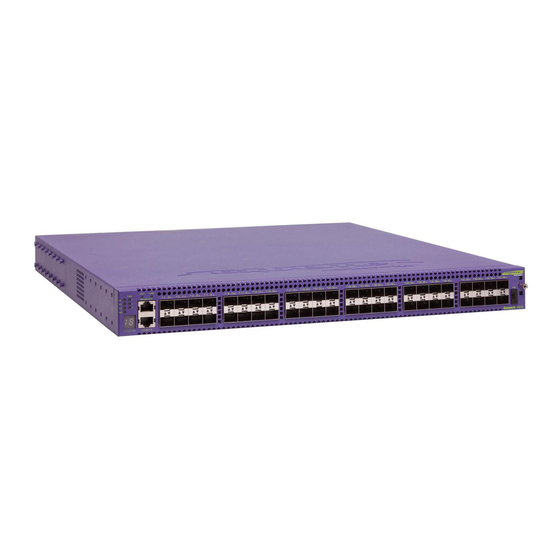
Page 16: Summit X150 Series Switches
2.4 Gbps or 4.8 Gbps. Models are available with PoE and without PoE. Each Summit X150 series switch has two combination ports that provide 10/100/1000 BASE-T or SFP connectivity for 2 Gbps of copper or fiber connectivity. -
Page 17: Summit X150-24P Switch
For more information about combination ports, see Combination Ports and Failover. For information about SFPs, see the Extreme Networks Pluggable Interface Modules Installation Guide. • LEDs to indicate port status and switch operating conditions. Summit Family Hardware Installation Guide... -
Page 18: Summit X150-48T Switch
Two combination ports (ports 49–50) using RJ-45 connectors and SFPs to provide 2 Gbps of copper or fiber connectivity For more information about combination ports, see Combination Ports and Failover. For information about SFPs, see the Extreme Networks Pluggable Interface Modules Installation Guide. Summit Family Hardware Installation Guide... -
Page 19: Summit X150 Series Switch Leds
The internal AC power supply operates from 100 VAC to 240 VAC. Figure 6: Summit X150-48t Switch Rear Panel Summit X150 Series Switch LEDs The following describes the meanings of the LEDs on the Summit X150 switches. Summit Family Hardware Installation Guide... - Page 20 Summit Family Switches LEDs on the Summit X150 Series Switches Table 8: Front Panel Label or Type Color/State Meaning MGMT Blinking green (fast) Power-on self-test (POST) in progress. Steady green POST passed. System is booting image. Blinking green (slow) Normal operation.
-
Page 21: Summit X250E Series Switches
Summit Family Switches Table 10: Rear Panel Label or Type Color/State Meaning Management Port Right LED: Link is OK. Steady green Left LED: Activity. Blinking green Both LEDs off Link is not present. Summit X250e Series Switches The Summit X250e series switches provide 24 or 48 Ethernet ports that deliver high-density fast Ethernet connectivity using fixed 10/100/1000BASE-T ports or installable small form pluggable (SFP) optical modules. -
Page 22: Summit X250E-24T Switch
For more information about combination ports, see Combination Ports and Failover. For information about SFPs, see the Extreme Networks Pluggable Interface Modules Installation Guide. • LEDs to indicate port status and switch operating conditions For a description of the LEDs and their operation, see Summit X250e Series Switch LEDs. -
Page 23: Summit X250E-24Tdc Switch
For more information about combination ports, see Combination Ports and Failover. For information about SFPs, see the Extreme Networks Pluggable Interface Modules Installation Guide. • LEDs to indicate port status and switch operating conditions For a description of the LEDs and their operation, see Summit X250e Series Switch LEDs. -
Page 24: Summit X250E-24P Switch
For more information about combination ports, see Combination Ports and Failover. For information about SFPs, see the Extreme Networks Pluggable Interface Modules Installation Guide. • LEDs to indicate port status and switch operating conditions For a description of the LEDs and their operation, see Summit X250e Series Switch LEDs. -
Page 25: Summit X250E-24X Switch
Two combination ports (ports 25–26) using RJ-45 connectors and SFPs to provide 2 Gbps of copper or fiber connectivity For more information about combination ports, see Combination Ports and Failover. For information about SFPs, see the Extreme Networks Pluggable Interface Modules Installation Guide. Summit Family Hardware Installation Guide... - Page 26 Summit Family Switches • LEDs to indicate port status and switch operating conditions For a description of the LEDs and their operation, see Summit X250e Series Switch LEDs. • Stack number indicator showing the position of this switch in a stacked configuration •...
- Page 27 Summit Family Switches For information about SFPs, see the Extreme Networks Pluggable Interface Modules Installation Guide. • LEDs to indicate port status and switch operating conditions For a description of the LEDs and their operation, see Summit X250e Series Switch LEDs.
-
Page 28: Summit X250E-48T Switch
For more information about combination ports, see Combination Ports and Failover. For information about SFPs, see the Extreme Networks Pluggable Interface Modules Installation Guide. • LEDs to indicate port status and switch operating conditions For a description of the LEDs and their operation, see Summit X250e Series Switch LEDs. - Page 29 For more information about combination ports, see Combination Ports and Failover. For information about SFPs, see the Extreme Networks Pluggable Interface Modules Installation Guide. • LEDs to indicate port status and switch operating conditions For a description of the LEDs and their operation, see Summit X250e Series Switch LEDs.
-
Page 30: Summit X250E-48P Switch
For more information about combination ports, see Combination Ports and Failover. For information about SFPs, see the Extreme Networks Pluggable Interface Modules Installation Guide. • LEDs to indicate port status and switch operating conditions For a description of the LEDs and their operation, see Summit X250e Series Switch LEDs. - Page 31 Summit Family Switches • Stack number indicator showing the position of this switch in a stacked configuration • Serial console port used to connect a terminal and perform local management Figure 21: Summit X250e-48p Switch Front Panel The rear panel of the Summit X250e-48p switch (shown in Figure 22: Summit X250e-48p Switch Rear Panel on page 31) includes:...
-
Page 32: Summit X250E Series Switch Leds
Summit Family Switches • In a 48-port configuration or any combination of ports where total PoE power does not exceed 370 watts, it provides 7.7 W to each port. If the total system demands exceed this power limit, you can specify one of the following: •... - Page 33 Summit Family Switches LEDs on the Summit X250e Series Switches Table 11: Front Panel Label or Type Color/State Meaning MGMT Blinking green (fast) Power-on self-test (POST) in progress Steady green POST passed. System is booting image. Blinking green (slow) Normal operation. Blinking amber Switch diagnostics are running.
-
Page 34: Summit X350 Series Switches
Summit Family Switches Table 12: Additional Port LED Meanings for PoE Switches: Summit X250e-24p & Summit X250e-48p Label or Type Color/State Meaning All front-panel Steady green Link OK. port not powered. ports Steady amber Link OK, port is powered, no traffic Blinking green Link OK, transmitting packets, port not powered. -
Page 35: Summit X350-24T Switch
For more information about combination ports, see Combination Ports and Failover. For information about SFPS, see the Extreme Networks Pluggable Interface Modules Installation Guide. • LEDs to indicate port status and switch operating conditions For a description of the LEDs and their operation, see Summit X350 Series Switch LEDs. -
Page 36: Summit X350-48T Switch
For more information about combination ports, see Combination Ports and Failover. For information about SFPs, see the Extreme Networks Pluggable Interface Modules Installation Guide. • LEDs to indicate port status and switch operating conditions Summit Family Hardware Installation Guide... - Page 37 Summit Family Switches For a description of the LEDs and their operation, see Summit X350 Series Switch LEDs. • Serial console port used to connect a terminal and perform local management Figure 25: Summit X350-48t Switch Front Panel The rear panel of the Summit X350-48t switch (shown in Figure 26: Summit X350-48t Switch Rear Panel on page 37) includes:...
-
Page 38: Summit X350 Series Switch Leds
Summit Family Switches Summit X350 Series Switch LEDs The following table describes the meanings of the LEDs on the Summit X350 series switches. Table 16: Front Panel Label or Type Color/State Meaning MGMT Blinking green (fast) Power-on self-test (POST) in progress. Steady green POST passed. -
Page 39: Summit X430 Series Switches
Two unpopulated 1000BASE-X SFP ports (ports 9–10) that provide 2 Gbps of fiber connectivity. Note All the eight 10/100/1000BASE-T ports and all of the 1000BASE-X SFP ports can be used simultaneously. For information about SFPs, see the Extreme Networks Pluggable Interface Modules Installation Guide. • Ethernet management port •... - Page 40 Four unpopulated 1000BASE-X SFP ports (ports 25–28) that provide 4 Gbps of fiber connectivity. Note All of the 10/100/1000BASE-T ports and four 1000BASE-X SFP ports can be used simultaneously. For information about SFPs, see the Extreme Networks Pluggable Interface Modules Installation Guide. • Ethernet management port •...
- Page 41 Four unpopulated 1000BASE-X SFP ports (ports 25–28) that provide 4 Gbps of fiber connectivity. Note All the twenty-four 10/100/1000BASE-T ports and all four of the 1000BASE-X SFP ports can be used simultaneously. For information about SFPs, see the Extreme Networks Pluggable Interface Modules Installation Guide. • Ethernet management port...
- Page 42 Four 1000BASE-X SFP ports (ports 49–52) that provide 4 Gbps of fiber connectivity. Note All the forty-eight 10/100/1000BASE-T ports and all four of the 1000BASE-X SFP ports can be used simultaneously. For information about SFPs, see the Extreme Networks Pluggable Interface Modules Installation Guide. Summit Family Hardware Installation Guide...
- Page 43 Summit Family Switches • Ethernet management port • Serial console port implemented as an RJ-45 connector, used to connect a terminal and perform local management • LEDs to indicate port status and switch operating conditions For a description of the LEDs and their operation, see Summit X430 LEDs.
-
Page 44: Summit X440 Series Switches
Summit Family Switches Table 19: X430 Front Panel LEDs (continued) Label or Type Color/State Meaning Steady green Normal operation, fan is good. Blinking amber Fan failure. Switch will continue to operate unless it overheats. No power Steady green Normal operation. (Internal power No power is attached/Power failure. - Page 45 Summit Family Switches Table 20: X440 Series Switches and Port Types (continued) 10/100/1000BASE-T 10/100/1000BASE-T 100/1000BASE-X 10G BASE-X SFP+ RJ45 POE+ RJ45 X440-24t-10G 4 (unpopulated 2 (unpopulated) combo ports) X440-24p-10G 24 (four are combo 4 (unpopulated 2 (unpopulated) ports) combo ports) X440-24x-10G 4 (combo ports) 24 (unpopulated)
- Page 46 • Four unpopulated SFP ports (ports 9–12) that provide 4 Gbps of fiber connectivity. The SFP ports support both 100BASE-FX and 1000BASE-X optical modules. For information about SFPs, see the Extreme Networks Pluggable Interface Modules Installation Guide. • Two high-performance stacking ports with associated LEDs •...
- Page 47 Four unpopulated SFP ports (ports 9–12) that provide 4 Gbps of fiber connectivity. The SFP ports support both 100BASE-FX and 1000BASE-X optical modules. For information about SFPs, see the Extreme Networks Pluggable Interface Modules Installation Guide. Summit Family Hardware Installation Guide...
- Page 48 Summit Family Switches • Two high-performance stacking ports with associated LEDs • Ethernet management port • Serial console port implemented as an RJ-45 connector, used to connect a terminal and perform local management • LEDs to indicate port status and switch operating conditions For a description of the LEDs and their operation, see Summit X440 Series Switch LEDs.
- Page 49 Summit Family Switches For information about SFPs, see the Extreme Networks Pluggable Interface Modules Installation Guide. • Ethernet management port • Serial console port implemented as an RJ-45 connector, used to connect a terminal and perform local management • LEDs to indicate port status and switch operating conditions...
- Page 50 Ports 21 through 24 are implemented as shared ports that pair a copper port with a fiber port. For more information about combination ports, see Combination Ports and Failover. For information about SFPs, see the Extreme Networks Pluggable Interface Modules Installation Guide. • Ethernet management port •...
- Page 51 Ports 21 through 24 are implemented as shared ports that pair a copper port with a fiber port. For more information about combination ports, see Combination Ports and Failover. For information about SFPs, see the Extreme Networks Pluggable Interface Modules Installation Guide. • Four autosensing 10/100/1000BASE-T ports (ports 21–24) that provide 4 Gbps of high-density copper connectivity.
- Page 52 Ports 21 through 24 are implemented as shared ports that pair a copper port with a fiber port. For more information about combination ports, see Combination Ports and Failover. For information about SFPs, see the Extreme Networks Pluggable Interface Modules Installation Guide. • Ethernet management port •...
- Page 53 Summit Family Switches Figure 45: Summit X440-L2-24t Switch Front Panel 1 = Ethernet management port 4 = Console port 2 = 10/100/1000BASE-T ports 5 = Combination ports 3 = SFP ports The rear panel of the Summit X440-L2-24t switch (shown in Figure 46: Summit X440-L2-24t Switch Rear Panel on page 53) includes:...
- Page 54 Summit Family Switches For information about SFPs, see the Extreme Networks Pluggable Interface Modules Installation Guide. • Ethernet management port • Serial console port implemented as an RJ-45 connector, used to connect a terminal and perform local management • LEDs to indicate port status and switch operating conditions...
- Page 55 Ports 21 through 24 are implemented as shared ports that pair a copper port with a fiber port. For more information about combination ports, see Combination Ports and Failover. For information about SFPs, see the Extreme Networks Pluggable Interface Modules Installation Guide. • Two unpopulated SFP+ ports (ports 25 and 26) that provide 20 Gbps of fiber connectivity •...
- Page 56 Ports 21 through 24 are implemented as shared ports that pair a copper port with a fiber port. For more information about combination ports, see Combination Ports and Failover. For information about SFPs, see the Extreme Networks Pluggable Interface Modules Installation Guide. • Two unpopulated SFP+ ports (ports 25 and 26) that provide 20 Gbps of fiber connectivity •...
- Page 57 Ports 21 through 24 are implemented as shared ports that pair a copper port with a fiber port. For more information about combination ports, see Combination Ports and Failover For information about SFPs, see the Extreme Networks Pluggable Interface Modules Installation Guide. •...
- Page 58 Ports 45 through 48 are implemented as shared ports that pair a copper port with a fiber port. For more information about combination ports, see Combination Ports and Failover. For information about SFPs, see the Extreme Networks Pluggable Interface Modules Installation Guide. Summit Family Hardware Installation Guide...
- Page 59 Summit Family Switches • Ethernet management port • Serial console port implemented as an RJ-45 connector, used to connect a terminal and perform local management. • LEDs to indicate port status and switch operating conditions. For a description of the LEDs and their operation, see Summit X440 Series Switch LEDs.
- Page 60 Ports 45 through 48 are implemented as shared ports that pair a copper port with a fiber port. For more information about combination ports, see Combination Ports and Failover. For information about SFPs, see the Extreme Networks Pluggable Interface Modules Installation Guide. • Ethernet management port •...
- Page 61 Ports 45 through 48 are implemented as shared ports that pair a copper port with a fiber port. For more information about combination ports, see Combination Ports and Failover. For information about SFPs, see the Extreme Networks Pluggable Interface Modules Installation Guide. • Ethernet management port •...
- Page 62 Ports 45 through 48 are implemented as shared ports that pair a copper port with a fiber port. For more information about combination ports, see Combination Ports and Failover. For information about SFPs, see the Extreme Networks Pluggable Interface Modules Installation Guide. • Ethernet management port •...
- Page 63 Ports 47 and 48 are implemented as shared ports that pair a copper port with a fiber port. For more information about combination ports, see Combination Ports and Failover. For information about SFPs, see the Extreme Networks Pluggable Interface Modules Installation Guide. • Two unpopulated SFP+ ports (ports 49 and 50) that provide 20 Gbps of fiber connectivity •...
- Page 64 Ports 47 and 48 are implemented as shared ports that pair a copper port with a fiber port. For more information about combination ports, see Combination Ports and Failover. For information about SFPs, see the Extreme Networks Pluggable Interface Modules Installation Guide. • Two unpopulated SFP+ ports (ports 49 and 50) that provide 20 Gbps of fiber connectivity •...
-
Page 65: Summit X440 Series Switch Leds
Summit Family Switches Figure 65: Summit X440-48p-10G Switch Front Panel 1 = Ethernet management port 5 = Console port 2 = 10/100/1000BASE-T PoE ports 6 = Combination ports 3 = SFP ports 7 = SFP+ ports 4 = Stack number indicator The rear panel of the Summit X440-48p-10G switch includes: •... - Page 66 Summit Family Switches Table 21: Front Panel Label or Type Color/State Meaning MGMT Blinking green Power-on self-test (POST) in progress. Steady green POST passed. Normal operation. Blinking amber System is disabled. POST failed or system overheated. No external power attached. Steady green Normal operation, fan is good.
-
Page 67: Summit X450, X450A, And X450E Series Switches
Summit Family Switches Table 21: Front Panel (continued) Label or Type Color/State Meaning Port number Steady green Link is OK. 21 – 24 or Blinking green Port is transmitting packets. 45 – 48 (Shared ports) Link is not present, or port is disabled. Port number Steady green Link is OK. -
Page 68: Summit X450 Series Switches
Summit Family Switches Each Summit X450, X450a, or X450e series switch has four combination ports that provide 10/100/1000 BASE-T or SFP connectivity for 4 Gbps of copper or fiber connectivity. A serial console port on the front panel allows you to connect a terminal and perform local management. An Ethernet management port on the back panel can be used to connect the system to a parallel management network for administration. -
Page 69: Summit X450-24T Switch
For more information about combination ports, see Combination Ports and Failover. For information about SFPS, see the Extreme Networks Pluggable Interface Modules Installation Guide. • LEDs to indicate port status and switch operating conditions For a description of the LEDs and their operation, see... -
Page 70: Summit X450-24X Switch
The front panel of the Summit X450-24x switch includes: • Twenty fixed SFP ports (ports 5–24) that provide 20 Gbps of high-density fiber connectivity For information about SFPS, see the Extreme Networks Pluggable Interface Modules Installation Guide. • Four combination ports (ports 1–4) using RJ-45 connectors and SFPs to provide 4 Gbps of copper... -
Page 71: Summit X450A Series Switches
Summit Family Switches The connecting redundant power supply cable is shipped with the EPS-160 unit. See EPS-160 External Power Module (with EPS-T) for more information. • AC power input socket The internal power supply operates from 100 VAC to 240 VAC. Figure 70: Summit X450-24x Switch Rear Panel Summit X450a Series Switches The Summit X450a series switches are 24-port or 48-port switches without PoE options. - Page 72 For more information about combination ports, see Combination Ports and Failover. For information about SFPs, see the Extreme Networks Pluggable Interface Modules Installation Guide. • LEDs to indicate port status and switch operating conditions For a description of the LEDs and their operation, see...
-
Page 73: Summit X450A-24Tdc Switch
For more information about combination ports, see Combination Ports and Failover. For information about SFPs, see the Extreme Networks Pluggable Interface Modules Installation Guide. • LEDs to indicate port status and switch operating conditions For a description of the LEDs and their operation, see... - Page 74 Summit Family Switches Figure 73: Summit X450a-24tDC Switch Front Panel The rear panel of the Summit X450a-24tDC switch (shown in Figure 74: Summit X450a-24tDC Switch Rear Panel on page 75) includes: • Slot for one of the Summit option cards listed in the following table. These port option cards allow you to add one or two high-speed uplink ports to the switch.
-
Page 75: Summit X450A-24X Switch
For more information about combination ports, see Combination Ports and Failover. For information about SFPs, see the Extreme Networks Pluggable Interface Modules Installation Guide. • LEDs to indicate port status and switch operating conditions For a description of the LEDs and their operation, see... -
Page 76: Summit X450A-24Xdc Switch
For more information about combination ports, see Combination Ports and Failover. For information about SFPs, see the Extreme Networks Pluggable Interface Modules Installation Guide. • LEDs to indicate port status and switch operating conditions Summit Family Hardware Installation Guide... - Page 77 Summit Family Switches For a description of the LEDs and their operation, see Summit X450, X450a, and X450e Series Switch LEDs. • Stack number indicator showing the position of this switch in a stacked configuration • Serial console port used to connect a terminal and perform local management Figure 77: Summit X450a-24xDC Switch Front Panel The rear panel of the Summit X450a-24xDC switch (Figure 78: Summit X450a-24xDC Switch Rear...
-
Page 78: Summit X450A-48T Switch
For more information about combination ports, see Combination Ports and Failover. For information about SFPs, see the Extreme Networks Pluggable Interface Modules Installation Guide. • LEDs to indicate port status and switch operating conditions For a description of the LEDs and their operation, see... -
Page 79: Summit X450A-48Tdc Switch
For more information about combination ports, see Combination Ports and Failover. For information about SFPs, see the Extreme Networks Pluggable Interface Modules Installation Guide. • LEDs to indicate port status and switch operating conditions For a description of the LEDs and their operation, see... - Page 80 Summit Family Switches Figure 81: Summit X450a-48tDC Switch Front Panel The rear panel of the Summit X450a-48tDC switch (Figure 82: Summit X450a-48tDC Switch Rear Panel on page 81) includes: • Slot for one of the Summit option cards listed in the following table. These port option cards allow you to add one or two high-speed uplink ports to the switch.
-
Page 81: Summit X450E Series Switches
For more information about combination ports, see Combination Ports and Failover. For information about SFPS, see the Extreme Networks Pluggable Interface Modules Installation Guide. • LEDs to indicate port status and switch operating conditions Summit Family Hardware Installation Guide... - Page 82 Summit Family Switches For a description of the LEDs and their operation, see LEDs on the Summit X450, X450a, and X450e Switches LEDs on the Summit X450, X450a, and X450e Switches. • Serial console port used to connect a terminal and perform local management The rear panel of the Summit X450e-24t switch (Figure 83: Summit X450e-24t Switch Rear Panel page 82) includes:...
- Page 83 Summit Family Switches For information about SFPs, see the Extreme Networks Pluggable Interface Modules Installation Guide. • LEDs to indicate port status and switch operating conditions For a description of the LEDs and their operation, see Summit X450, X450a, and X450e Series Switch LEDs.
-
Page 84: Summit X450E-24P Switch
Four combination ports (ports 21–24) using RJ-45 connectors and SFPs to provide 4 Gbps of copper or fiber connectivity For more information about combination ports, see Combination Ports and Failover. For information about SFPs, see the Extreme Networks Pluggable Interface Modules Installation Guide. Note All 24 ports can provide PoE power. •... -
Page 85: Summit X450E-48P Switch
Summit Family Switches • Slot for one of the Summit option cards listed in the following table. These port option cards allow you to add one or two high-speed uplink ports to the switch. Table 32: Port Option Cards for Summit X450e Series Switches Option Card Model Type of Added Ports For More Information, see . - Page 86 Summit Family Switches For information about SFPs, see the Extreme Networks Pluggable Interface Modules Installation Guide. Note All 48 ports can provide PoE power • LEDs to indicate port status and switch operating conditions For a description of the LEDs and their operation, see...
- Page 87 Summit Family Switches Figure 89: Summit X450e-48p Switch Rear Panel Summit X450e-48p Power Supplies Internal Power Supply The Summit X450e-48p switch is powered by both an internal power supply and an optional external redundant power supply system. The internal Summit X450e-48p power supply can provide 370 W of PoE power, as follows: •...
- Page 88 Summit Family Switches Internal Power EPS-600LS (1x) EPS-600LS (2x) EPS-600LS (3x) External Power Supply/ Supply Status Chassis Failed/ Disconnected Internal Power 370 W of 740 W of 740 W of 370 W of Supply: redundant power external power only external power only internal power only Power On Internal power supply...
- Page 89 Summit Family Switches Table 34: Front Panel (continued) Label or Type Color/State Meaning PSU-E Steady green Normal operation (External power supply) Blinking amber Failure No external power attached. Ethernet Ports Steady green Link OK 1 – 24 or 1 – 48 Blinking green Activity (21 –...
-
Page 90: Summit X460 Series Switches
Summit Family Switches Summit X460 Series Switches The Summit X460 series switches are 24-port or 48-port switches that provide Ethernet connectivity using fixed 10/100/1000BASE-T RJ-45 ports or installable SFP or SFP+ optical modules. Two Summit X460 models support the PoE+ IEEE 802.3at standard and provide up to 30 Watts of power per port. - Page 91 Ports 21 through 24 are implemented as shared ports that pair a copper port with a fiber port. For more information about combination ports, see Combination Ports and Failover. For information about SFPs, see the Extreme Networks Pluggable Interface Modules Installation Guide. • 10/100/1000 Mbps management port •...
- Page 92 • Four unpopulated SFP ports (ports 49–52) that provide 4 Gbps of fiber connectivity. The SFP ports support both 100BASE-FX and 1000BASE-X optical modules. For information about SFPs, see the Extreme Networks Pluggable Interface Modules Installation Guide. • 10/100/1000 Mbps management port •...
- Page 93 • Twenty-four unpopulated SFP ports (ports 1–24) that provide 24 Gbps of fiber connectivity. The SFP ports support both 100BASE-FX and 1000BASE-X optical modules. For information about SFPs, see the Extreme Networks Pluggable Interface Modules Installation Guide. • Eight fixed autosensing 10/100/1000BASE-T ports (ports 21–28) that provide 8 Gbps of high- density copper connectivity Ports 21 through 24 are implemented as shared ports that pair a copper port with a fiber port.
- Page 94 100BASE-FX and 1000BASE-X optical modules. All the front-panel ports on the Summit X460-48x switch support Synchronous Ethernet. For information about this feature, see the ExtremeXOS Concepts Guide. For information about SFPs, see the Extreme Networks Pluggable Interface Modules Installation Guide. •...
- Page 95 Ports 21 through 24 are implemented as shared ports that pair a copper port with a fiber port. For more information about combination ports, see Combination Ports and Failover. For information about SFPs, see the Extreme Networks Pluggable Interface Modules Installation Guide. • 10/100/1000 Mbps management port •...
- Page 96 • Four unpopulated SFP ports (ports 49–52) that provide 4 Gbps of fiber connectivity. The SFP ports support both 100BASE-FX and 1000BASE-X optical modules. For information about SFPs, see the Extreme Networks Pluggable Interface Modules Installation Guide. • 10/100/1000 Mbps management port •...
-
Page 97: Summit X460 Series Switch Leds
Summit Family Switches Figure 100: Summit X460-48p Switch Front Panel The rear panel of the Summit X460-48p switch (Figure 101: Summit X460-48p Switch Rear Panel page 97) includes: • Two slots for port option cards or stacking modules (see Port Option Cards for Summit X460 Series Switches) •... -
Page 98: Summit X460-48P
Summit Family Switches Table 39: Front Panel LEDs Label or Type Color/State Meaning MGMT Steady green Power-on self test (POST) completed successfully; normal operation. Blinking green POST is in progress. Blinking amber POST failed, or the system has over-heated. No external power attached. Steady green Normal operation. -
Page 99: Summit X480 Series Switches
Summit Family Switches Table 41: Additional Port LED meanings for PoE switches: Summit X460-24p & Summit X460-48p (continued) Label or Type Color/State Meaning Management Port Steady green Link OK Blinking green Activity No link, or port is disabled. Table 42: Back Panel Label or Type Color/State Meaning... - Page 100 The SFP ports support both 100BASE-X and 1000BASE-X optical modules. For more information about combination ports, see Combination Ports and Failover. For information about SFPs, see the Extreme Networks Pluggable Interface Modules Installation Guide. • Two unpopulated 10-Gbps XFP-based ports •...
- Page 101 The front panel of the Summit X480-48x switch includes: • Forty-eight 100/1000BASE-X SFP ports that provide 48 Gbps of high-density fiber connectivity For information about SFPs, see the Extreme Networks Pluggable Interface Modules Installation Guide. • 10/100/1000 Mbps management port •...
- Page 102 The SFP ports support both 100BASE-X and 1000BASE-X optical modules. For more information about combination ports, see Combination Ports and Failover. For information about SFPs, see the Extreme Networks Pluggable Interface Modules Installation Guide. • 10/100/1000 Mbps management port •...
-
Page 103: Summit X480 Series Switch Leds
Summit Family Switches Figure 106: Summit X480-48t Switch Front Panel The rear panel of the Summit X480-48t switch (Figure 107: Summit X480-48t Rear Panel on page 103) includes: • Slot for a VIM2 virtual interface module (see Versatile Interface Modules for the Summit X480 Series Switches •... - Page 104 Summit Family Switches Table 44: Front Panel LEDs (continued) Label or Type Color/State Meaning Steady green Normal operation Blinking green (rapid) Power-on self test (POST) is in progress. Blinking amber Failure No power PSU-1 Steady green Normal operation Blinking amber Failure No power;...
-
Page 105: Summit X650 Series Switches
Summit Family Switches Table 47: Back Panel (continued) Label or Type Color/State Meaning XFP Port LED Steady green Link OK (on installed VIM) Blinking green Activity Port is disabled. Summit X650 Series Switches The Summit X650 series switches have 24 front-panel Ethernet ports that provide 10-gigabit Ethernet connectivity using fixed 10GBASE-T RJ-45 ports or installable SFP+ optical modules. - Page 106 Summit Family Switches The Summit X650 series switch must have an installed VIM; the switch will not operate correctly without one. Note The Summit X650 switches require VIM1 or VIM3 modules. Other VIM types that may appear to be mechanically compatible with the Summit X650 switches will not function if they are installed in these switches.
- Page 107 Summit Family Switches Figure 109: Summit X650-24t Rear Panel Summit X650-24x Switch The front panel of the Summit X650-24x switch includes: • Twenty-four ports that can use 10GBASE-X SFP+ optical modules. (Ports 1–24 can also be populated with 1000BASE-X SFP modules.) For information about supported optical modules, see the latest version of the ExtremeXOS Release Notes.
-
Page 108: Summit X650 Series Switch Leds
Summit Family Switches Figure 111: Summit X650-24x Rear Panel Summit X650 Series Switch LEDs The following table describes the LEDs on the Summit X650 series switches. Table 49: Front Panel LEDs Label or Type Color/State Meaning MGMT Blinking green Normal operation Blinking amber Power-on self test (POST) failed;... -
Page 109: Summit X670 Series Switches
Summit Family Switches Table 50: 2-digit Stack number Indicator (continued) Label or Type Color/State Meaning Ethernet Ports Steady green Link OK 1 – 24 Blinking green Activity Management Port Steady green Link OK Blinking green Activity Table 51: Back Panel Label or Type Color/State Meaning... - Page 110 • Forty-eight unpopulated optical ports that can accommodate 10GBASE-X SFP+ or 1000BASE-X SFP optical modules to provide high-density fiber connectivity For information about SFP+ and SFP optical modules, see the Extreme Networks Pluggable Interface Modules Installation Guide. • 10/100/1000-Mbps management port •...
- Page 111 • Forty-eight unpopulated optical ports that can accommodate 10GBASE-X SFP+ or 1000BASE-X SFP optical modules to provide high-density fiber connectivity For information about SFP+ and SFP optical modules, see the Extreme Networks Pluggable Interface Modules Installation Guide. • 10/100/1000-Mbps management port •...
- Page 112 Forty-four 100/1000/10000 BASE-T copper ports plus four combo ports of 10G BASE-X SFP+ and 10G BASE-T (1G/10G dual speed for the combo ports) For information about SFP+ and SFP optical modules, see the Extreme Networks Pluggable Interface Modules Installation Guide.
-
Page 113: Summit X670 Series Switch Leds
Summit Family Switches Figure 116: Summit X670V-48t Front Panel Table 52: Summit X670V-48t Front Panel 1 = Stack number indicator 4 = 10G BASE-T (100 Mbps/1G/10G Tri-speed) ports 2 = Console port 5 = SFP+ ports 3 = Ethernet management port 6 = Combination ports (1G/10G only) The rear panel of the Summit X670-48t switch (Figure 117: Summit X670V-48t Rear Panel... - Page 114 Summit Family Switches Table 53: Front Panel LEDs (continued) Label or Type Color/State Meaning Steady green Normal operation. 1, 2, 3 Blinking amber Failure. No power. P1, P2 Steady green Normal operation. (Power Supply) Steady amber Power is attached, but no power is on. Blinking amber Power failure.
-
Page 115: Summit X770 Series Switches
Summit Family Switches Table 55: Back Panel Label or Type Color/State Meaning QSFP+ port LED (on Steady green Link OK installed VIM3 module) Blinking green Activity Summit X770 Series Switches The Summit X770 series switches have 32 front-panel Ethernet ports that can provide 40-gigabit Ethernet connectivity using installable QSFP+ optical modules. - Page 116 Table 56: X770-32q 40G and 10G Port Numbering 1 = 40G mode (32 ports) 2 = 10G mode (104 ports) For information about QSFP+ optical modules, see the Extreme Networks Pluggable Interface Modules Installation Guide. • Groups of two or four ports configurable to be stacking ports as shown in the following table:...
- Page 117 Summit Family Switches • LEDs to indicate port status and switch operating conditions.. For a description of the LEDs and their operation, see Summit X770 Series Switch LEDs on page 117 • Stack number indicator. X770-32 -q Table 58: Summit X770-32q Front Panel 1 = USB port 4 = 40G/10G QSFP+ Ethernet ports 2 = Stack number indicator...
- Page 118 Summit Family Switches Table 60: Front Panel LEDs Label or Type Color/State Meaning M (Management) Steady green Power-on self test (POST) has finished. This is normal operation. Blinking green POST in progress. Blinking amber POST failed. No external power is attached. Steady green Normal operation.
-
Page 119: Pluggable Interfaces For Summit Family Switches
Many Summit family switches include ports that are compatible with a variety of optical modules, including SFP, SFP+, QSFP+, and XFP modules. Extreme Networks optical modules are tested to work in all supported Extreme Networks devices. We recommend that all customers use Extreme Networks optical modules in their Extreme Networks devices. -
Page 120: Chapter 2: Summit Power Supplies
An optional redundant power supply can be added to most Summit models to protect against a power supply failure and to provide increased support for PoE operation on applicable switches. The following Summit switch series use external power supplies for redundancy: • Summit X150 series • Summit X250e series •... - Page 121 Summit Power Supplies External Power Supplies Table 62: Summit X150 Series Switches Switch Model Compatible EPS Model Number Summit X150-24t EPS-160 External Power Module with EPS-T EPS-160: 10907 EPS-T: 10906 Summit X150-24x EPS-160 External Power Module with EPS-T EPS-160: 10907...
- Page 122 Summit Power Supplies Table 66: Summit X440 Series Switches Switch Model Compatible EPS Model Number Summit X440-24t Summit 750 W Power Supply with EPS-C2 chassis EPS-C2: 10936 Power supply: 10931 Summit X440-L2-24t Summit 750 W Power Supply with EPS-C2 chassis EPS-C2: 10936 Power supply: 10931 Summit X440-24p...
- Page 123 EPS-160 External Power Module (with EPS-T) The EPS-160 External Power Module (Model 10907) is a modular power supply for use with the EPS-T chassis. You can use the EPS-160 as a redundant power supply with the following Extreme Networks switches: • Summit X150-24t switch •...
- Page 124 Each EPS-160 power supply is shipped with a special redundant power supply cord. Figure 119: EPS-160 Redundant Power Cord Connector EPS-LD External Power Supply Unit You can use the Extreme Networks EPS-LD External Power Supply Unit (Model 45019) as a redundant power supply with the following Extreme Networks switches: •...
- Page 125 The Extreme Networks EPS-500 External Power Supply Unit (Model 10911) provides additional power to compatible Power over Ethernet (PoE) switches and other Extreme switches. You can use the EPS-500 power supply as a redundant power supply with the following Extreme Networks switches: •...
-
Page 126: Poe Redundant Power Configurations
Note An AC power input cord is not provided with the EPS-600LS power module. You can order an appropriate cord from Extreme Networks or from your local supplier. The power cord must meet the requirements listed in Power Cord Requirements for AC-Powered Switches and AC Power Supplies. - Page 127 Summit Power Supplies Table 70: POE Power Behavior Internal Power EPS-600LS (1x) EPS-600LS (2x) EPS-600LS (3x) External Power Supply/ Supply Status Chassis Failed/ Disconnected Internal Power 370 W of 740 W of 740 W of 370 W of Supply: redundant power external power only external power only internal power only...
- Page 128 Summit Power Supplies Internal Power Supply Failure with Single EPS-600LS Module When an EPS-C with a single EPS-600LS is connected to the Summit X450e-48p or X250e-48p switch and the internal power supply fails, power is drawn from the EPS-600LS without power interruption to the PoE-connected devices.
- Page 129 EPS-150DC External Power Module (with EPS-T2) The EPS-150DC External Power Module (Model 10909) is a modular power supply for use in the EPS-T2 External Power System Tray. You can use the EPS-150DC as a redundant power supply with the following Extreme Networks switches: •...
- Page 130 Summit 750 W AC power supplies (Model 10931). For more information about the 750 W AC power supply including LED meanings, see Summit 750-Watt AC Power Supply. The EPS-C2 system is compatible with the following Extreme Networks switches: • Summit X440-24t switch •...
- Page 131 Summit Power Supplies The following table lists the power capability in watts of the EPS-C2 based on the number of installed PSUs. Check the power requirements of your switches to determine how many PSUs you need to install into the EPS-C2 chassis. 12V Power (W) PoE Power (W) 1 PSU...
- Page 132 Summit Power Supplies Switch Internal One installed Two installed 750W Three installed 750W External Power Supply/ Power Supply 750W PoE PSU PoE PSU PoE PSU Chassis Failed/ Status Disconnected Power On 370 W of 740 W of external 740 W of external 370 W of internal redundant power power only...
-
Page 133: Summit Replaceable Internal Power Supplies
Summit X670V-48x-BF Summit X770-32q-FB Summit X770-32q-BF * Extreme networks does not recommend combining an AC and DC power supply in the same Summit X650 series switch. Note An AC power input cord is not provided with a Summit AC power supply. You can order an appropriate cord from Extreme Networks or from your local supplier. - Page 134 Summit Power Supplies • Summit 300W DC power supply (Model 10933) • Summit 300W DC power supply (Model 10934A) The Summit 300 W power supplies (AC and DC) have the status LEDs listed in the following table. Table 72: Summit 300 W LED Status Indications LED Label and Color Meaning In OK...
- Page 135 Summit Power Supplies These power supplies are compatible with Summit X670 switch models that have the same airflow direction as the power supply. In a redundant power configuration, the airflow direction must be the same for both power supplies, and it must match the airflow direction of the fans in the switch. The Summit 550 W power supplies have the status LEDs listed in the following table.
- Page 136 These power supplies are compatible with the Summit X650 series switches. Note Extreme Networks does not recommended using the Summit 850 W DC power supply in combination with a Summit 850 W AC power supply in the same Summit X650 series switch.
-
Page 137: Chapter 3: Summit Option Cards And Versatile Interface Modules
Summit Option Cards and Versatile Interface Modules Overview Summit XGM-2xn Option Card Summit XGM2-2xn Option Card Summit XGM2-2xf Option Card Summit XGM2-2sf Option Card Summit XGM2-2bt Option Card Versatile Interface Modules for the Summit X650 Series Switches Versatile Interface Modules for the Summit X480 Series Switches Optional Ports for the Summit X460 Series Switches VIM4-40G4X Versatile Interface Module for the Summit X670 Switch This section describes port option cards, versatile interface modules (VIMs), and stacking modules that... -
Page 138: Summit Xgm-2Xn Option Card
Summit Option Cards and Versatile Interface Modules Table 77: Summit Card, VIM, and Module Compatibility Card or Name No. of Type of Ports Compatible Switch Series Module Ports Type 10-Gbps XGM-2xn XENPAK optical I/O ports Summit X450 I/O Port XGM2-2xn XENPAK optical I/O ports Summit X450a, X450e XGM series... -
Page 139: Summit Xgm2-2Xn Option Card
For current information about compatible XENPAK modules and the minimum required software, refer to the most recent version of the ExtremeXOS Hardware and Software Compatibility Matrix. For more information about XENPAK modules, refer to the Extreme Networks Pluggable Interface Modules Installation Guide. -
Page 140: Summit Xgm2-2Xf Option Card
For current information about compatible XENPAK modules and the minimum required software, refer to the most recent version of the ExtremeXOS Hardware and Software Compatibility Matrix. For information about XENPAK modules, refer to the Extreme Networks Pluggable Interface Modules Installation Guide. -
Page 141: Summit Xgm2-2Sf Option Card
For current information about compatible XFP modules and the minimum required software, refer to the most recent version of the ExtremeXOS Hardware and Software Compatibility Matrix. For more information about XFP modules, refer to the Extreme Networks Pluggable Interface Modules Installation Guide. -
Page 142: Versatile Interface Modules For The Summit X650 Series Switches
Summit Option Cards and Versatile Interface Modules In Summit X450a and X450e series switches, the ports on the XGM2-2bt option card can be configured as alternate stacking ports in a SummitStack configuration that uses the SummitStack-V feature. For more information about stacking Summit family switches, see Summit Family Switches. - Page 143 Summit X650 series switches. Each switch must have an installed VIM1-SummitStack512 module. To connect these ports, you must use stacking cables with compatible connectors, available from Extreme Networks. The VIM1-SummitStack512 module requires ExtremeXOS 12.3.3 software (or later) installed on the Summit X650 series switch.
- Page 144 The VIM1-SummitStack256 versatile interface module provides two 128-Gbps SummitStack stacking ports. To connect these ports, you must use stacking cables with compatible connectors, available from Extreme Networks. The VIM1-SummitStack256 module requires ExtremeXOS 12.4.1 software (or later) installed on the Summit X650 series switch.
-
Page 145: Versatile Interface Modules For The Summit X480 Series Switches
Summit Option Cards and Versatile Interface Modules Figure 130: VIM3-40G4X Versatile Interface Module 1 = QSFP+ port 2 = Port LEDs Versatile Interface Modules for the Summit X480 Series Switches A VIM2 or VIM3 versatile interface module can be installed in a dedicated slot at the back of the Summit X480 series switch to provide high speed stacking ports or 10-Gbps Ethernet ports. - Page 146 The VIM2-SummitStack128 versatile interface module provides two 64-Gbps SummitStack stacking ports. To connect these ports, you must use stacking cables with compatible connectors, available from Extreme Networks. Figure 133: VIM2-SummitStack128 Versatile Interface Module VIM2-SummitStack-V80 Versatile Interface Module The VIM2-SummitStack-V80 versatile interface module provides two unpopulated cages for QSFP+ optical modules or QSFP+ compatible active or passive cables.
-
Page 147: Optional Ports For The Summit X460 Series Switches
Summit Option Cards and Versatile Interface Modules Figure 134: VIM2-SummitStack-V80 Module VIM3-40G4X Versatile Interface Module The VIM3-40G4X versatile interface module provides four unpopulated cages for QSFP+ optical modules or QSFP+ compatible direct-attach active or passive cables. Ports 25 and 26 can be enabled as alternate stacking ports for the Summit X480 series switch. Each physical port can be configured to operate as a single 40-Gbps port or as four 10-Gbps ports. - Page 148 For current information about compatible SFP+ modules and the minimum required software, refer to the most recent version of the ExtremeXOS Hardware and Software Compatibility Matrix. For more information about SFP+ modules, refer to the Extreme Networks Pluggable Interfaces Hardware Installation Guide.
-
Page 149: Summit X460 Series Stacking Modules
B on the rear panel of a Summit X460 series switch. These ports allow you to combine multiple units into a single SummitStack management entity, using stacking cables that are available from Extreme Networks. Two stacking modules are available for the Summit X460 series switches (see... -
Page 150: Vim4-40G4X Versatile Interface Module For The Summit X670 Switch
Summit Option Cards and Versatile Interface Modules SummitStack SummitStack-V80 Module Module XGM3SB-4sf Port Option Card The XGM3SB-4sf option card allows you to add up to four 10-Gigabit SFP+ optical ports to Slot B on the rear panel of the Summit X460 series switch. These ports support synchronous Ethernet (Sync-E). - Page 151 Summit Option Cards and Versatile Interface Modules Figure 141: VIM4-40G4X Versatile Interface Module 1 = QSFP+ port 2 = Port LEDs Summit Family Hardware Installation Guide...
-
Page 152: Chapter 4: Site Preparation
2 Evaluating and meeting cable requirements. After examining your physical site and verifying that all environment requirements are met, evaluate and compare your existing cable plant with the requirements of the Extreme Networks equipment to determine if you need to install new cables. -
Page 153: Meeting Site Requirements
Site Preparation To run your equipment safely, you must meet the specific power requirements for each switch and external power supply unit installed in the system. For power specifications of the switches, see the specific switch listings in Technical Specifications. For power specifications of the external power supplies, see Summit External Power Supplies. - Page 154 Temperature Extreme Networks equipment generates a significant amount of heat. It is essential that you provide a temperature-controlled environment for both performance and safety. Install the equipment only in a temperature- and humidity-controlled indoor area that is free of airborne materials that can conduct electricity.
-
Page 155: Rack Specifications And Recommendations
Maintain a storage temperature of -40° to 158° F (-40° to 70° C). Note As with all electrical equipment, Extreme Networks product lifetimes degrade with increased temperature. Ifpossible, temperatures should be kept at approximately 78° F (25° C) or lower. - Page 156 This will ensure good grounding between the chassis, rack, and earth ground. Note Because building codes vary worldwide, Extreme Networks strongly recommends that you consult an electrical contractor to ensure proper equipment grounding for your specific installation.
- Page 157 Extra room on each side is optional. Warning Extreme Networks switches do not have a switch for turning power to the unit on and off. For systems using an AC power supply, power to the switch is disconnected by removing the wall plug from the electrical outlet.
-
Page 158: Evaluating And Meeting Cable Requirements
2 Assign a unique block of sequential numbers to the group of cables that run between each pair of wiring closets. 3 Assign a unique identification number to each equipment rack. 4 Identify all wiring closets by labeling the front panel of your Extreme Networks equipment and other hardware. 5 Keep accurate and current cable identification records. - Page 159 Site Preparation • When installing a patch panel using twisted pair wiring, untwist no more than 1 inch (2.54 cm) of the cable to avoid radio frequency (RF) interference. • Discharge the RJ-45 Ethernet cable before plugging it into a port on the switch. Caution Unshielded twisted pair (UTP) cable can build up ESD charges when being pulled into a new installation.
- Page 160 Every cable has a minimum bend radius, example, and fibers will be damaged if the cables are bent too sharply. It is also important not to stretch the cable during installation. Extreme Networks recommends that the bend radius for fiber optic cable equal 2 inches (5.08 cm) minimum for each 90-degree turn as shown in the following figure.
- Page 161 – 10BASE-T Category 3 and higher UTP cable – * Proprietary to Extreme Networks. Connections between two Extreme Networks 1000BASE-LX interfaces that use 10/125 µm single-mode fiber can use a maximum distance of 10,000 meters. Summit Family Hardware Installation Guide...
- Page 162 Site Preparation Table 81: Extreme Networks Direct-Attach Cables Cable Type Model Number Length SFP+ passive copper cable 10304 1 meter 10305 3 meters 10306 5 meters 10307 10 meters QSFP+ passive copper cable 10311 0.5 meter 10312 1 meter 10313...
-
Page 163: Meeting Power Requirements
Site Preparation Not recommended Best 0.1" = 1mm actual Better 39.37% : 254% SPG_001 Figure 145: RJ-45 Connector Jacket Types Radio Frequency Interference If you use UTP cabling in an installation, take precautions to avoid RF interference. RF interference can cause degradation of signal quality, and, in an Ethernet network environment, can cause excessive collisions, loss of link status, or other physical layer problems that can lead to poor performance or loss of communication. -
Page 164: Power Supply Requirements
Specifications. Identify and Purchase of Power Cords Extreme Networks equipment does not ship with power cords. Click the following link for locating the correct power cord for purchase and use on specific Extreme Networks equipment. Specifications for power cords in each country are also provided within this link allowing end user to purchase cords locally. -
Page 165: Applicable Industry Standards
Transition time is the time that is necessary for the UPS to transfer from utility power to full-load battery power. For Extreme Networks products, a transition time of less than 20 milliseconds is required for optimum performance. DC Power Requirements This system should be installed in a DC-I battery return configuration. - Page 166 Site Preparation • ANSI/TIA/EIA-606—discusses cabling system administration. • ANSI/TIA/EIA-607—discusses commercial building grounding and bonding requirements. You can access these standards at: www.ansi.org www.tiaonline.org Summit Family Hardware Installation Guide...
-
Page 167: Chapter 5: Building Stacks
Building Stacks Building Stacks Overview Stacking Methods and Summit Switches Stacking Cables Placing Summit Family Switches for Stacked Operation Using the SummitStack-V Feature Connecting the Switches to Form the Stack Ring Example SummitStack-V Feature Connecting Stacking Cables Connecting Console Ports for a Stack Management Port Cabling Stacking Port LEDs Stack Number Indicator LEDs... -
Page 168: Slot Numbers
Building Stacks Stack Port 1 Stack Port 2 SummitStack cables Summit switches Stack Port 1 Stack Port 2 Stack Port 1 Stack Port 2 Stack Port 1 Stack Port 2 Figure 146: Summit Switches Connected in a SummitStack Configuration The stack operates as a single switch with a single IP address and a single point of authentication. One switch, called the stack master, controls the stack. -
Page 169: Stacking Methods And Summit Switches
Building Stacks About Redundancy When your stack is operational, one switch is the primary (or master) switch that is responsible for running network protocols and managing the stack To provide recovery in case of a break in the stack connections, you can configure redundancy by designating a backup switch to take over as master if the master switch fails. - Page 170 Building Stacks Table 82: Summit Stacking by Stacking Method Stacking Method Speed per Link (HDX) Cable Type and Summit Switch Lengths SummitStack 10 Gbps 0.5m, 1.5m, 3.0m, 5.0m, Summit X250, X440, X450a/e, 20Gbps Stacking Cable X460, X480, X650 (VIM1) Note: X650 cannot use the 5.0m cable.
- Page 171 Building Stacks Table 83: Switch Series and Summit Stacking (continued) Summit Switch Stacking Method Speed per Link (HDX) Cable Type and Lengths Summit X450a/e SummitStack 10 Gbps 0.5m, 1.5m, 3.0m, 5.0m (Rear panel) 20Gbps Stacking Cable SummitStack-V 10 Gbps 0.5m - 100m SFP+, XFP, XENPAK (SR, LR, ER), 10GBASE-T Summit X460...
-
Page 172: Combining Switches From Different Series
Building Stacks Table 83: Switch Series and Summit Stacking (continued) Summit Switch Stacking Method Speed per Link (HDX) Cable Type and Lengths Summit X650 SummitStack 10 Gbps 0.5m, 1.5m, 3.0m (with VIM1-SummitStack) 20Gbps Stacking Cable SummitStack-V (with 10 Gbps 0.5m - 40km VIM1-10G8X and SFP+ VIM3-40G4X) - Page 173 Building Stacks Table 84: Summit Switches and Stacking Methods Stack X250e X450e X440* X440-1 X450a X460 X480 X650 X670 X670V X770 with X250e X450e 40G, V 40G 40G, V 40G, V 40G, V 40G, V V X440* X440-10 X450a 40G, V 40G 40G, V 40G, V 40G, V 40G, V V X460 40G, V 40G...
-
Page 174: Stacking Cables
Stacking connections using the native stacking ports require stacking cables that are specific to the type of stacking port. These cables are available from Extreme Networks in lengths from 0.5 meter to 100 meters. The following table lists the cable types and compatible Summit switches or modules. -
Page 175: Placing Summit Family Switches For Stacked Operation
26 AWG, 2 meters Note Additional types of stacking cables may have been released since this guide was published. Contact your Extreme Networks sales representative for the most recent information about available cables. Placing Summit Family Switches for Stacked Operation... -
Page 176: Using The Summitstack-V Feature
• Because of the weight of the cable, Extreme Networks strongly recommends the use of cable management hardware to support the cables and provide strain relief at the connectors when you use the SummitStack 128G cable, SummitStack 64G cable, or SummitStack 128G/64G cable. (See Connecting Stacking Cables.) - Page 177 Building Stacks When you connect distant nodes using alternate stacking ports, be sure to run the cables over physically different pathways to reduce the probability of a cut occurring to both links. See the following table for the ports that are available on each switch model that supports this feature. For each switch model, the column labeled Alternate Stacking Port 1 shows the switch port that replaces native stacking port 1, and Alternate Stacking Port 2 lists the switch port that replaces native stacking port 2.
-
Page 178: Summary Of Conditions For Alternate Stacking Ports
Building Stacks Table 86: Alternate Stacking Ports (continued) Switch Model Type or location of Native Alternate Alternate Location of Alternate Stacking Ports Stacking Stacking Stacking Ports Port 1 Port 2 Summit X480-48t None (VIM has only data ports) S3 (51) S4 (52) VIM2-10G4X module Summit X480-48x... - Page 179 Building Stacks Summit X450a and X450e series switches: To use the SummitStack-V feature, you must install one of the following port option cards to add 10- Gbps ports to the switch. • XGM2-2xf option card • XGM2-2xn option card • XGM2-2sf option card •...
-
Page 180: Connecting The Switches To Form The Stack Ring
Building Stacks Connecting the Switches to Form the Stack Ring After you have installed the individual Summit switches, connect the switches together using the stacking cables. The examples in this section show cable connections and the recommended order for connecting ports to facilitate the easy setup configuration. - Page 181 Building Stacks The following table lists the recommended order for connecting the stacking ports in this example. Connect this slot and port ..To this slot and port Slot 1 Stack Port 2 Slot 2 Stack Port 1 Slot 2 Stack Port 2...
- Page 182 Building Stacks The following figure shows an example of a four-switch stack that includes two Summit X650 series switches. In the Summit X650 series switches, the SummitStack ports are on installed VIM1- SummitStack modules. The Summit X650 series switches are placed at the top of the stack and will be designated the stack master and backup nodes.
- Page 183 Building Stacks Slot 1 Summit X480 Slot 2 Summit X480 Slot 4 Summit X650 Slot 3 Summit X480 Figure 151: SummitStack Connections Using Four Summit Switches with SummitStack Ports on VIMs The following table lists the recommended order for connecting the stacking ports in this example. Connect this slot and port .
- Page 184 Building Stacks Connect this slot and port ..To this slot and port Slot 4 Rack E Port 2 Slot 5 Rack C Port 1 Slot 5 Rack C Port 2 Slot 1 (Rack A Port 1 Single-Rack Stacking Configurations These examples show stacks of either four or eight switches in a single rack.
- Page 185 Building Stacks Slot 1 Slot 2 Slot 3 Slot 4 Slot 5 Slot 6 Slot 7 Slot 8 Figure 154: SummitStack Cable Connections Using Eight Summit Switches with Integrated SummitStack Ports The following table lists the recommended order for connecting the stacking ports in this example. Connect this slot and port .
-
Page 186: Combining Different Types Of Stacking Ports
Building Stacks Slot 1 Slot 2 Slot 3 Slot 4 Figure 155: SummitStack Configuration Using SummitStack X650 Series Switches and SummitStack 40G Cables The following figure shows an example of a four-switch stack that combines two Summit X650 series switches and two Summit X460 series switches. In the Summit X650 series switches, the stacking ports are on installed VIM1-SummitStack modules. - Page 187 Building Stacks Figure 157: Combining Stacking Port Types—A The following cables are used to make the stacking connections: • SummitStack 128G cable between the two Summit X650 series switches at the top (slot 1 and slot 2) • SummitStack 128G/20G stacking cable between the Summit X650 series switch and the Summit X480 series switch (between slot 2 and slot 3) •...
- Page 188 Building Stacks • SummitStack 128G cable between the two Summit X650 series switches at the top (slot 1 and slot 2) • SummitStack 128G/20G stacking cable between the Summit X650 series switch and the Summit X460 series switch (between slot 2 and slot 3) •...
- Page 189 Building Stacks Figure 159: Using the SummitStack-V80 Stacking Module or VIM2-SummitStack-V80 Module Using SummitStack-V160 Stacking A stacking rate of 160 Gbps can be achieved using certain configurations of Summit switches. For example, a Summit X670V (X670V-48x or X670V-48t) switch can be connected to a Summit X650 series switch through 40-Gbps stacking connections that provide 160 Gbps full duplex bandwidth.
- Page 190 Building Stacks Slot 1 X670V-48x with VIM4-40G4X 1 2 3 4 Slot 2 X670V-48x with VIM4-40G4X Slot 3 X650-48x with VIM3-40G4X Slot 4 X480 with VIM2-Summit S tack-V80 Slot 5 X460 with SummitStack-V80 Figure 160: SummitStack-V160 Configuration The following table lists the recommended order for connecting the stacking ports in this example. Connect this slot and port .
- Page 191 Building Stacks Slot 1: Summit X670V-48x switch with VIM4-40G4X Slot 2: Summit X670V-48x switch with VIM4-40G4X Slot 3: Summit X650 series switch with VIM3-40G4X SummitStack V-320 stacking can be done with installable modules or using front panel ports, depending upon the type of switch you have. For SummitStack V-320 Stacking using the VIM3-40G4X and VIM4-40G4X modules, connections between the stacking ports must be done using paired bundles of physical ports.
- Page 192 Building Stacks Connect this slot and port ..To this slot and port Slot 1 Stack Port 2 (physical ports 2 and Slot 2 Stack Port 1 (physical ports 1and Slot 2 Stack Port 2 (physical ports 2 and Slot 3 Stack Port 1 (physical ports 1 and Slot 3...
-
Page 193: Example Summitstack-V Feature
Building Stacks Example SummitStack-V Feature The following shows an example of a stacking configuration that combines native and alternate stacking ports to form a stack of seven switches. The Summit X650 series switches in slots 1 and 2 are connected through their native stacking ports on installed VIM1-SummitStack256 modules, using SummitStack128 stacking cables. -
Page 194: Connecting Stacking Cables
Building Stacks Figure Using the SummitStack-V Feature with Summit X670 Series Switchesshows a stack that combines Summit X670 series switches with Summit X650 and X460 series switches in a stack of five switches. The Summit X670 series switches in slots 1 and 2 are connected through their alternate stacking ports using fiber optic cables. - Page 195 Connect a SummitStack 128G Cable Because of the weight of the SummitStack 128G cable, Extreme Networks strongly recommends the use of cable management hardware to support the cables and provide strain relief at the connectors. Figure 166: Cable Management Using a J-Shaped Support Bracket...
- Page 196 Building Stacks Figure 166: Cable Management Using a J-Shaped Support Bracket SH_124 Figure 167: Cable Management Using Tie-Wraps and a Stand-Off Port Covers on the VIM1-SummitStack512 Module On the VIM1-SummitStack512 module, EMI-protective covers are installed over the port connectors. Before connecting the stacking cables, remove the connector covers from the ports that will be used. To remove a connector cover: Summit Family Hardware Installation Guide...
- Page 197 Building Stacks On the side of the connector nearest to the inserter/ejector lever, find the notch between the two end tabs on the cover (see Figure 168: Removing a Connector Cover on page 197). 2 At the notch, set a small flat-blade screwdriver firmly against the connector housing. Figure 168: Removing a Connector Cover 3 Brace the screwdriver against the module inserter/ejector lever and pry the end of the connector cover loose.
- Page 198 Building Stacks Holding the cable connector with the release tab on top, align the connector with the stacking port on the VIM1 module in the Summit X650 series switch (see Figure 169: Connecting a SummitStack 128G Cable on page 198). Figure 169: Connecting a SummitStack 128G Cable 2 Firmly press the cable connector into the stacking port until the spring latch on top of the connector clicks into place.
- Page 199 Building Stacks a Holding the cable connector with the release tab on top, align the connector with the stacking port on the VIM1 module in the Summit X650 series switch. Figure 170: Connecting the 128G Connector b Firmly press the cable connector into the stacking port until the spring latch on top of the connector clicks into place.
- Page 200 The 128-Gbps stacking ports are on VIM1-SummitStack256 modules; the 64-Gbps stacking ports are on VIM2-SummitStack128 modules. Because of the weight of the SummitStack 128G/64G cable, Extreme Networks strongly recommends the use of cable management hardware to support the cables and provide strain relief at the connectors.
- Page 201 Building Stacks SH_170 Figure 173: Cable Management Using Tie-Wraps and Stand-Offs At the Summit X650 series switch, connect the 128G connector to the VIM1-SummitStack256 module. At the Summit X480 series switch, connect the 64G connector to the VIM2-SummitStack128 module. The connection process is the same for each connector and the compatible VIM model. To connect a 128G or 64G connector: Holding the cable connector with the release tab on top, align the connector with the stacking port on the VIM1.
- Page 202 SummitStack 64G cables are used to connect the 64-Gbps stacking ports on the VIM2-SummitStack128 module in Summit X480 series switches. Because of the weight of the SummitStack 64G cable, Extreme Networks strongly recommends the use of cable management hardware to support the cables and provide strain relief at the connectors.
- Page 203 Building Stacks Figure 175: Cable Management Using a J-Shaped Support Bracket Figure 176: Cable Management Using Tie-Wraps and Stand-Offs To connect a SummitStack 64G cable: Summit Family Hardware Installation Guide...
- Page 204 Building Stacks Holding the cable connector with the release tab on top, align the connector with the stacking port on the VIM2 module in the Summit X480 series switch (see Figure 177: Connecting a SummitStack 64G Cable on page 204). Figure 177: Connecting a SummitStack 64G Cable 2 Firmly press the cable connector into the stacking port until the spring latch on top of the connector clicks into place.
- Page 205 Building Stacks a Holding the cable connector with the release tab on top, align the connector with the stacking port on the VIM2 module in the Summit X480 series switch. Figure 178: Connecting the 64G Connector b Firmly press the cable connector into the stacking port until the spring latch on top of the connector clicks into place.
-
Page 206: Connecting Console Ports For A Stack
Building Stacks • SummitStack-V80 stacking module installed in a Summit X460 series switch • VIM2-SummitStack-V80 module installed in a Summit X480 series switch To connect a QSFP+ direct-attach cable: Holding the QSFP+ connector by its sides, insert the connector into the port on the switch. Figure 180: Connecting a QSFP+ Direct-Attach Cable to a SummitStack-V80 Module Passive copper cable (top) -
Page 207: Management Port Cabling
Building Stacks Management Port Cabling Connect the master, backup, and all other master-capable switches to your management network using the Ethernet management port on the rear panel of each switch. If you choose the default redundancy setup, only slots 1 and 2 are allowed to become master. You may connect all switch management ports in the stack if you choose to do so. -
Page 208: Chapter 6: Installing Summit Family Switches
Installing Summit Family Switches Safety Information Installing a Summit Family Switch (Models Other than Summit X430-8p, X460, X480, X650, X670 and X770 Series) Installing a Summit X460 Series Switch Installing a Summit X430-8p Series Switch Installing AC Power Supplies in Summit X460 Series Switches Installing a Model 10933 or 10934A 300 W DC Power Supply in a Summit X460 Series Switch Installing a Summit X480 Series Switch... -
Page 209: Safety Information
Installing a Summit Family Switch (Models Other than Summit X430-8p, X460, X480, X650, X670 and X770 Series) This section describes how to install the following Summit family switches: • Summit X150 series • Summit X250e series • Summit X350 series •... - Page 210 Installing Summit Family Switches • Ground the switch (DC-powered units only). • Connect a redundant power supply (if applicable). • Connect power cables. • Connect network interface cables. If you are installing Summit family switches for use in a SummitStack configuration, read Summit Family Switches before you install the switches.
- Page 211 Installing Summit Family Switches Figure 181: Attaching the Mounting Bracket Summit X350, X440, X450, X450a, and X450e, series Summit X150 and X250e series 4 Repeat steps 2 and 3 for the other side of the switch. Summit Family Hardware Installation Guide...
- Page 212 Installing Summit Family Switches 5 Slide the switch into the rack (see Figure 182: Installing a Switch in a Rack on page 212). Take care to load the rack so that it is not top-heavy. Start installing equipment at the bottom of the rack and work up.
- Page 213 Installing Summit Family Switches The pads keep the switch from scratching the supporting surface and help ensure adequate airflow around the switches when they are mounted on top of one another. Caution You can not stack any switches on top of a desk mounted X430-8p switch. Do not place any equipment on top of a desktop mounted Summit X430-8p switch.
- Page 214 Installing Summit Family Switches • Summit X450a-24xDC • Summit X450a-48tDC You must adhere to specific safety requirements when you connect to a DC power source for one of these Summit switches. Note For centralized DC power connection, these products are intended to be installed in Restricted Access Locations (dedicated equipment rooms, equipment closets, or the like) in accordance with Articles 110-16, 110-17, and 110-18 of the National Electric Code, ANSI/NFPA An optional redundant power supply, the EPS-150DC, is available for use with the Summit...
- Page 215 Installing Summit Family Switches Figure 184: Location of the Grounding Lug Summit X450a series DC-powered switch Summit X250e series DC-powered switch 3 Insert the stripped wire into the grounding lug. Figure 185: Attaching the Ground Wire to a Summit x450a Series Switch Figure 186: Attaching the Ground Wire to a Summit X250e Series Switch 4 Using a straight-tip torque screwdriver, tighten the retaining screw to 20 pound-inches (2.25 Newton-meters).
- Page 216 Installing Summit Family Switches Connecting the X250 or X450 DC Wiring Harness to the DC Source Voltage A three-wire, 6-foot long DC wiring harness is included with the Summit family X250 or X450 DC- powered switch. The DC wiring harness must be properly connected to the DC source voltage at your facility by a qualified electrician before you attach the connector on the wiring harness to the DC power supply socket on the switch.
- Page 217 Installing Summit Family Switches Gather the following materials to ground the Summit X440 DC-powered switch: • Stranded copper wire cable, minimum size 14 AWG, maximum size 6 AWG The wire should be long enough to reach from the installed switch to the facility ground point •...
- Page 218 Installing Summit Family Switches Figure 189: Attaching the Ground Wire to a Summit X440 DC Series Switch 1=Grounding lug 2=Tighten with screwdriver Note The DC power terminal is covered by a plastic shield when shipped. Remove the shield to access the terminals. 3 Using a cross-head (Phillips) torque screwdriver, tighten the retaining screw to 20 pound-inches (2.25 Newton-meters).
- Page 219 Installing Summit Family Switches Verify that the DC circuit is de-energized. 2 Connect the DC power input cables as follows: a On each terminal, loosen the screw enough to allow the spade terminal to slide underneath the captive square washer (see Figure 190: Connecting the DC Power Cables on page 219).
-
Page 220: Installing A Summit X460 Series Switch
Installing Summit Family Switches Plug the DC wiring harness connector into the DC power supply socket on the rear of the switch (see the figure below). The pins must align properly for the cable to completely connect. Do not force the cable into the socket until the keyway is aligned properly. - Page 221 Installing Summit Family Switches Pre-installation Requirements Installing the Summit X460 series switch requires two people to maneuver the switch and attach mounting hardware. Make sure there is adequate space behind the rack to provide access for installing power supplies, port option cards, and stacking modules.
- Page 222 Installing Summit Family Switches 4 Repeat step to attach the other bracket to the other side of the switch. SH_197 Figure 192: Attaching a Rack-mounting Flange 5 Slide the switch into the equipment rack. SH_198 Figure 193: Installing the Summit X460 Series Switch 6 Secure the mounting bracket flanges to the rack, using screws that are appropriate for the rack.
- Page 223 Installing Summit Family Switches To install a stacking module, see Installing an Option Card or Port Option Card in Slot B of a Summit X460 Series Switch. Installing Summit DC-Powered Switches This section provides additional details about installing the following Summit DC-powered switches: •...
- Page 224 Installing Summit Family Switches • Additional grounding hardware appropriate to the earth ground connection at your site Warning Be sure to connect the chassis ground wire before you connect any power cables. To ground the switch: At one end of the wire, strip the insulation to expose 1/2 inch (12 mm) of bare wire. 2 Identify the grounding lug on the back of the switch.
- Page 225 Installing Summit Family Switches Figure 196: Attaching the Ground Wire to a Summit X250e Series Switch 4 Using a straight-tip torque screwdriver, tighten the retaining screw to 20 pound-inches (2.25 Newton-meters). 5 Connect the other end of the wire to a known reliable earth ground point at your site. Connecting the X250 or X450 DC Wiring Harness to the DC Source Voltage A three-wire, 6-foot long DC wiring harness is included with the Summit family X250 or X450 DC- powered switch.
- Page 226 Installing Summit Family Switches Figure 197: Three-wire Cable Harness Note Each wire on the harness has been properly marked for proper attachment to the DC power source. Leave these labels on each lead wire for future reference. Attaching the DC Wiring Harness to the DC Power Socket on the Switch After the DC wiring harness is connected to a permanent DC voltage source by a qualified, licensed electrician, you can remove, replace, and maintain the Summit DC-powered switch without further electrician assistance.
-
Page 227: Installing A Summit X430-8P Series Switch
Installing Summit Family Switches Plug the DC wiring harness connector into the DC power supply socket on the rear of the switch (see the figure below). The pins must align properly for the cable to completely connect. Do not force the cable into the socket until the keyway is aligned properly. - Page 228 • AC power cord for each unit. Extreme Networks equipment does not ship with power cords. Click the following link for locating the correct power cord for purchase and use on specific Extreme Networks equipment. Specifications for power cords in each country are also provided within this link allowing end user to purchase cords locally.
-
Page 229: Installing Ac Power Supplies In Summit X460 Series Switches
An AC power cord is not included with a Summit AC power supply. You can purchase AC power cords for use in the US and Canada from Extreme Networks or from your local supplier. The cord must meet the requirements listed under... - Page 230 Installing Summit Family Switches If necessary, remove a blank panel from the back of the Summit X460 series switch. Figure 201: Removing a Blank Panel 2 Verify that the power supply is right side up (see Figure 202: Installing a Power Supply on page 230).
-
Page 231: Installing A 750 W Ac Power Supply In A Summit X460 Series Switch
Installing Summit Family Switches 6 Connect the other end of the power cord to an AC power outlet. Warning Always be sure that the source outlet is properly grounded before plugging the AC power cord into the AC power supply. To install a second power supply, repeat steps 1 through 6. - Page 232 Installing Summit Family Switches 4 Push the power supply in until the latch snaps into place. Caution Do not slam the power supply into the switch. Figure 204: Installing a 750 W AC Power Supply Note If power supplies are not installed in both power supply bays, be sure to install a cover over the unoccupied bay.
- Page 233 Installing Summit Family Switches a If necessary, slide the plastic cord retainer farther away from the back of the switch (Figure 205: Moving the Power Cord Retainer on page 233). Figure 205: Moving the Power Cord Retainer b Connect the AC power cord to the input connector (Figure 206: Connecting the Power Cord page 233).
-
Page 234: Installing A Model 10933 Or 10934A 300 W Dc Power Supply In A Summit X460 Series Switch
Installing Summit Family Switches c Open the clip and slip it over the barrel of the connector (Figure 207: Attaching the Power Cord Retainer on page 234). Figure 207: Attaching the Power Cord Retainer d Snap the clip firmly around the connector. 6 Connect the other end of the power cord to an AC power outlet. -
Page 235: Required Tools And Materials
Installing Summit Family Switches Required Tools and Materials You need the following tools and materials to install or remove a 300 W DC power supply in a Summit X460 series switch: • Two spade terminals (Tyco part number 328281 or equivalent) for connecting the input power cables (provided) •... -
Page 236: Installing The Power Supply
Installing Summit Family Switches Figure 208: Attaching Power Connection Terminals to Cables Figure 209: Attaching ground terminal to cable Installing the Power Supply Caution The handle on the Summit 300 W DC power supply is not designed to be used to lift or carry the Summit X460 series switch. - Page 237 Installing Summit Family Switches 2 If necessary, remove a blank panel from the back of the Summit X460 series switch. Figure 210: Removing a Blank Panel 3 Verify that the power supply is right side up (see the figures below). 4 Carefully slide the power supply all the way into the power supply bay (see the figures below).
-
Page 238: Connecting The Ground Cable
Installing Summit Family Switches Connecting the Ground Cable Warning Be sure to connect the chassis ground wire before you connect any power cables. Warning Be sure to disconnect the ground wire after you disconnect all power cables. To connect the ground wire: Verify that the DC circuit is de-energized. -
Page 239: Connecting The Power Supply To The Dc Source Voltage
Installing Summit Family Switches 1 = Grounding point 2 = Ground wire Connecting the Power Supply to the DC Source Voltage The DC power connection at your facility must be made by a qualified electrician, following the instructions in this section. There are two 300W DC power supplies available: Model 10933 (recommended) and Model 10934A. - Page 240 Installing Summit Family Switches c Slide the spade terminal of the positive wire (+24 V) under the captive square washer on the positive terminal (+24V). d Tighten both screws on the terminal block to 11 inch-pounds (1.25 Newton-meters). +24V -24V (–) Figure 215: Connecting the DC Power Cables (Part 1) 5 Slide the cover into place over the terminal block.
- Page 241 Installing Summit Family Switches 7 Energize the DC circuit. Leave the ESD strap permanently connected to the rack, so that the strap is always available when you need to handle ESD-sensitive components. Connecting the Model 10933 or 10934A DC power supply to a -48V source To connect the DC power input cables on the Model 10933 or 10934A power supplies to a -48V source: Verify that the DC circuit is de-energized.
- Page 242 Installing Summit Family Switches c Slide the spade terminal of the positive wire (–48 V RTN) under the captive square washer on the positive terminal (labeled RTN). -48V (–) Figure 217: Connecting the DC Power Cables (Part 1) d Tighten both screws on the terminal block to 11 inch-pounds (1.25 Newton-meters) (Figure 218: Connecting the DC Power Cables (Part 2) on page 243).
-
Page 243: Installing A Summit X480 Series Switch
Installing Summit Family Switches 5 Slide the cover into place over the terminal block. Figure 218: Connecting the DC Power Cables (Part 2) 6 Connect the cables to the DC source voltage, using hardware appropriate to the installation site and following local and national electrical codes. -
Page 244: Selecting Rear Mounting Brackets
Installing Summit Family Switches If you are installing Summit X480 series switches for use in a SummitStack configuration, read Summit Family Switches before you install the switches. Note Take care to load the rack so that it is not top-heavy. Start installing equipment at the bottom and work up. - Page 245 Installing Summit Family Switches Mid-Mount the Switch in a Two-Post Rack Use the shorter rear mounting brackets for a mid-mounted switch. To mid-mount the switch in a two-post rack: Attach an ESD-preventive wrist strap to your wrist and connect the metal end to an appropriate ground point on the rack.
- Page 246 Installing Summit Family Switches 4 Push the switch forward as far as it will go, until the bracket support pegs are against the T of the mounting bracket (see the following figure). a Securely tighten the rack mounting screws. Figure 221: Fastening the Rear Mounting Brackets 5 At the front of the switch, place a front mounting bracket against each side of the switch, in front of the ventilation openings in the side of the switch.
- Page 247 Installing Summit Family Switches 7 Slide the switch back in the rack until the front mounting brackets are against the front of the rack post. Figure 223: Securing the Front Mounting Brackets to the Rack 8 Using mounting screws suitable for your equipment rack, secure the mounting brackets to the front of the rack post.
- Page 248 Installing Summit Family Switches 3 Insert and tighten seven screws to secure the bracket to the side of the switch. Figure 224: Attaching a Front Mounting Bracket 4 Repeat steps 2 and 3 to attach the remaining front bracket to the other side of the switch. 5 Slide the switch into the rack until the mounting bracket flanges are against the rack posts (see Figure 225: Front-Mounting a Switch on page 248).
- Page 249 Installing Summit Family Switches After the switch is secured to the rack, install and connect power supplies as described on Installing a Summit 450 W or 550 W AC Power Supply for AC power supplies or on Installing a Summit 450 W or 550 W DC Power Supply for DC power supplies.
- Page 250 Installing Summit Family Switches a Position the bracket with the flange at the front edge of the switch. Figure 227: Attaching a Front Mounting Bracket 5 From the front of the rack, slide the switch onto the rear mounting brackets. Figure 228: Installing the Switch—Four-Post Installation Summit Family Hardware Installation Guide...
-
Page 251: Installing Summit 450 W And 550 W Power Supplies
Installing Summit Family Switches 6 Slide the switch all the way into the rack and secure the mounting brackets to the front posts using suitable screws. Figure 229: Securing the Switch to the Front Rack Posts—Four-Post Installation After the switch is secured to the rack, install and connect power supplies as described in Installing a Summit 450 W or 550 W AC Power Supply for AC power supplies or in... -
Page 252: Installing A Summit 450 W Or 550 W Ac Power Supply
An AC power cord is not included with the Summit AC power supply. You can purchase AC power cords for use in the US and Canada from Extreme Networks or from your local supplier. The cord must meet the requirements listed in... - Page 253 Installing Summit Family Switches 2 If you are installing the power supply in a Summit X670 series switch: a Verify that the switch chassis has been grounded (see step on page 279 ). b Verify that the airflow direction for the power supply is the same as the airflow direction of the installed fan modules in the switch.
-
Page 254: Installing A Summit 450 W Or 550 W Dc Power Supply
Installing Summit Family Switches 7 To install a second power supply, repeat steps 3 through 5. Note If power supplies are not installed in both power supply bays, be sure to install a cover over the unoccupied bay. Unoccupied bays must always be covered to maintain proper system ventilation and EMI levels. - Page 255 Installing Summit Family Switches DC power and grounding cables are not included with the 450 W or 550 W DC power supply. You must provide the #14 AWG stranded copper cable. Recommended insulation colors are: • Red for the –48V connection (–) •...
- Page 256 Installing Summit Family Switches 3 If necessary, remove a blank panel from the back of the Summit X480 or X670 series switch. SH _ 157 Figure 233: Removing a Blank Panel 4 Verify that the power supply is right side up (see Figure 234: Installing a DC Power Supply on page 256).
- Page 257 Installing Summit Family Switches Connecting the Ground Wire Warning Be sure to connect the chassis ground wire before you connect any power cables. Warning Be sure to disconnect the ground wire after you disconnect all power cables. You need a #1 Phillips screwdriver to secure the ground wire to the power supply. To connect the ground wire: Verify that the DC circuit is de-energized.
- Page 258 Installing Summit Family Switches c Tighten the screw to 7 inch-pounds (0.99 Newton meters) (see Figure 236: Securing the Ground Wire on page 258). Figure 236: Securing the Ground Wire 6 Connect the other end of the wire to a known reliable earth ground point at your site. Connecting the Power Supply to the DC Source Voltage The DC power connection at your facility must be made by a qualified electrician, following the instructions in this section.
- Page 259 Installing Summit Family Switches a On each terminal, loosen the screw enough to allow the spade terminal to slide underneath the captive square washer (see Figure 237: Connecting the DC Power Cables (Part 1) on page 260). b Slide the spade terminal of the negative wire (–48 V) under the captive square washer on the negative terminal (labeled –).
- Page 260 Installing Summit Family Switches c Slide the spade terminal of the positive wire (–48 V RTN) under the captive square washer on the positive terminal (labeled +). (–) -48V SH _ 161 Figure 237: Connecting the DC Power Cables (Part 1) d Tighten both screws on the terminal block to 7 inch-pounds (0.99 Newton meters).
-
Page 261: Installing A Summit X650 Series Switch
Installing Summit Family Switches 3 Snap the cover into place over the terminal block. 4 Connect the cables to the DC source voltage, using hardware appropriate to the installation site and following local and national electrical codes. 5 Energize the DC circuit. Installing a Summit X650 Series Switch The Summit X650 series switch fits into a standard 19-inch equipment rack. - Page 262 Installing Summit Family Switches • AC power cord for each installed AC power supply An AC power cord is not included with the Summit X460 series switch. You must obtain a power supply cord that meets the requirements listed under Power Cord Requirements for AC-Powered Switches and AC Power Supplies.
- Page 263 Installing Summit Family Switches 3 From the back of the equipment rack, slide the switch into place over the mounting brackets. Make sure the brackets slide between the support pegs on both sides of the switch. Figure 240: Sliding the Switch onto the Rear Mounting Brackets 4 Push the switch forward as far as it will go, until the bracket support pegs are against the T of the mounting bracket (see Figure 241: Fastening the Rear Mounting Brackets—Two-Post Rack...
- Page 264 Installing Summit Family Switches 5 At the front of the switch, place a front mounting bracket against each side of the switch, in front of the ventilation openings in the side of the switch. Make sure there is space between the bracket and the ventilation openings. Figure 242: Positioning the Front Mounting Brackets—Two-Post Rack 6 Using the provided screws, attach each front bracket to the switch (see Figure 242: Positioning the...
- Page 265 Installing Summit Family Switches 7 Slide the switch back in the rack until the front mounting brackets are against the front of the rack post. Make sure that the ventilation holes in the side of the switch are within the open channel of the rack post.
- Page 266 Installing Summit Family Switches At the back of the cabinet, attach a rear mounting bracket to each rear post. Figure 244: Attaching Rear Mounting Brackets—Cabinet Installation 2 Attach an ESD-preventive wrist strap to your wrist and connect the metal end to an appropriate ground point on the rack.
- Page 267 Installing Summit Family Switches 5 From the front of the cabinet, slide the switch onto the rear mounting brackets. Figure 246: Installing the Switch—Cabinet Installation Summit Family Hardware Installation Guide...
-
Page 268: Installing Summit X650 Power Supplies
An AC power cord is not included with the Summit 850 W AC power supply. You can purchase AC power cords for use in the US and Canada from Extreme Networks or from your local supplier. The cord must meet the following requirements listed in... -
Page 269: Installing An 850 W Ac Power Supply In A Summit X650 Series Switch
Installing Summit Family Switches Installing an 850 W AC Power Supply in a Summit X650 Series Switch Caution Make sure that the AC power supply circuit is not overloaded. Use proper over-current protection, such as a circuit-breaker, to prevent over-current conditions. To install an 850 W AC power supply in a Summit X650 series switch: Attach an ESD-preventive wrist strap to your bare wrist and connect the metal end to an appropriate grounding point. -
Page 270: Installing An 850 W Dc Power Supply In A Summit X650 Series Switch
Installing Summit Family Switches 5 Push the power supply in until the latch snaps into place. Caution Do not slam the power supply into the switch. Figure 249: Installing a Power Supply 6 To install a second power supply, repeat steps on page 331 and on page 331. - Page 271 Installing Summit Family Switches 2 Insert the power supply into the Summit X650 series switch (see Installing the Power Supply. 3 Connect the ground (see Connecting the Ground Cable). 4 Have a qualified licensed electrician connect the power supply to the DC source voltage (see Connecting the Power Supply to the DC Source Voltage).
- Page 272 Installing Summit Family Switches Figure 250: Attaching Power Connection Terminals to Cables Figure 251: Attaching ground terminal to cable Installing the Power Supply Caution The handle on the Summit X650 DC power supply is not designed to be used to lift or carry the Summit X650 series switch.
- Page 273 Installing Summit Family Switches 3 Carefully slide the power supply all the way into the power supply bay (see Figure 253: Installing an 850 W DC Power Supply on page 273). 4 Push the power supply in until the latch snaps into place. Caution Do not slam the power supply into the switch.
- Page 274 Installing Summit Family Switches 1 = Grounding point 2 = Ground wire 3 Insert an M3.5 screw (provided) through the ring terminal and into the grounding point on the power supply. 4 Tighten the screw to 12.6 inch-pounds. 5 Connect the other end of the wire to a known reliable earth ground point at your site. Connecting the Power Supply to the DC Source Voltage The DC power connection at your facility must be made by a qualified electrician, following the instructions in this section.
- Page 275 Installing Summit Family Switches c Slide the spade terminal of the positive wire (–48 V RTN) under the captive square washer on the positive terminal (labeled RTN). -48V (–) SH_111 Figure 255: Connecting the DC Power Cables (Part 1) d Tighten both screws on the terminal block to 11 inch-pounds (1.2 Newton-meters) (Figure 256: Connecting the DC Power Cables (Part 2) on page 276).
-
Page 276: Installing A Summit X670 Or X770 Series Switch
Installing Summit Family Switches 4 Slide the cover into place over the terminal block. Figure 256: Connecting the DC Power Cables (Part 2) 5 Connect the cables to the DC source voltage, using hardware appropriate to the installation site and following local and national electrical codes. - Page 277 Installing Summit Family Switches If you are installing Summit X670 or X770 series switches for use in a SummitStack configuration, read Summit Family Switches before you install the switches. Note Take care to load the rack so that it is not top-heavy. Start installing equipment at the bottom of the rack and work up.
- Page 278 Installing Summit Family Switches Mid-Mounting a X670 or X770 Switch in a Two-Post Rack On one side of the switch, set a mounting bracket against the switch housing, with the flange toward the back of the switch (see Figure 257: Attaching a Rack-mounting Bracket (X670 shown) on page 278).
- Page 279 Installing Summit Family Switches 5 Secure the mounting bracket flanges to the rack, using screws that are appropriate for the rack. (Rack-mounting screws are not provided.) 6 Ground the switch if grounding lug is present (X670 series switches). a Strip 0.25 inch from the end of the AWG # 14 copper wire. b Securely crimp the provided ring terminal onto the stripped wire.
- Page 280 Installing Summit Family Switches c Repeat steps a and b to attach the other bracket to the other side of the switch. Figure 260: Attaching a Rack-mounting Bracket (X670 shown) 2 Slide the switch into the equipment rack. Figure 261: Installing the Summit X670 or X770 Series Switch (X670 shown) 3 Secure the mounting bracket flanges to the rack, using screws that are appropriate for the rack.
- Page 281 Installing Summit Family Switches c Insert the provided M4 screw through the ring terminal and into the grounding stud on the front of the switch (Figure 262: Grounding a Summit X670 Series Switch on page 281). d Securely tighten the screw. Figure 262: Grounding a Summit X670 Series Switch The Summit X670 and X770 series switches are shipped without installed power supplies.
- Page 282 Installing Summit Family Switches c Repeat steps a and b to attach the other bracket to the other side of the switch. Figure 263: Attaching a Rack-mounting Bracket (X670 shown) 2 From the front of the rack, slide the switch into the equipment rack. Figure 264: Installing the Summit X670 or X770 Series Switch (X670 shown) 3 Secure the front-mounting bracket flanges to the rack, using screws that are appropriate for the rack.
- Page 283 Installing Summit Family Switches 4 At the rear of the rack or cabinet, for each side, slide the rear mounting brackets (rails) between the two rows of pegs on either side of the switch. Figure 265: Inserting the Rear Mounting Brackets Between the Pegs on the Side of the Switch 5 Secure the rear mounting brackets to the rack posts using suitable screws.
-
Page 284: Connecting Network Interface Cables
Installing Summit Family Switches c Insert the provided M4 screw through the ring terminal and into the grounding stud on the front of the switch (#i739419/image_lj1_dvh_bm on page 284). d Securely tighten the screw. Figure 266: Grounding a Summit X670 Series Switch The Summit X670 and X770 series switches are shipped without installed power supplies. -
Page 285: Initial Management Access
Parity—None • Flow control—XON/XOFF The terminal or PC with terminal-emulation software that you connect to an Extreme Networks switch must be configured with these settings. This procedure is described in the documentation supplied with the terminal. Summit Family Hardware Installation Guide... -
Page 286: Logging In For The First Time
Installing Summit Family Switches Appropriate cables are available from your local supplier, or you can make your own. To ensure the electromagnetic compatibility of the unit, use only shielded serial cables. For connector pinouts associated with the console port, see Console Connector Pinouts. - Page 287 Installing Summit Family Switches 7 Save your configuration changes so that they will be in effect after the next system reboot by typing: save The configuration is saved to the configuration database of the switch. Note For more information about saving configuration changes, see the ExtremeXOS Concepts Guide.
-
Page 288: Chapter 7: Installing Summit External Power Supplies
Installing an EPS-C2 Chassis Read the information in the following sections thoroughly before you start to install or remove an external power supply. Safety Only trained service personnel should perform service to Extreme Networks switches and their components. Summit Family Hardware Installation Guide... -
Page 289: Pre-Installation Requirements
Warning Extreme Networks AC power supplies do not have switches for turning the unit on and off. Remove the wall plug from the electrical outlet to disconnect the power to an Extreme Networks AC power supply. Make sure that this connection is easily accessible. -
Page 290: Installing An Eps-160 External Power Module (With Eps-T)
You can order the EPS-T chassis with one or two EPS-160 power supplies already installed. You can also order an additional power supply from your Extreme Networks reseller. The EPS-T can be mounted in a rack or placed free-standing on a table. - Page 291 Installing Summit External Power Supplies Connecting the EPS-160 Power Supply to the Switch One end of the EPS-160 redundant power cord has a keyed connector to ensure correct alignment of the connector. The key is a plastic tab on the cord connector housing that fits into the EPS-160 unit. Figure 268: Redundant Power Cord Connector Caution Always connect the redundant power supply cord before you attach the AC power cord to...
-
Page 292: Installing An Eps-Ld External Power Supply
You can position the EPS-LD facing either the front or the back of the rack. For this reason, each unit has two sets of mounting holes on each side. Extreme Networks recommends that you position the Summit Family Hardware Installation Guide... - Page 293 Installing Summit External Power Supplies EPS-LD so that the power output connectors on the EPS-LD unit are on the same side as the external connector on the connecting switch. Caution Do not use the rack-mount brackets to suspend the EPS-LD from under a table or desk, or to attach the unit to a wall.
- Page 294 4 Slide the EPS-LD into a 19-inch rack and secure it using appropriate rack-mount screws. Note Extreme Networks recommends that you position the EPS-LD so that the output connectors are on the same side as the external connector on the connecting switch. If...
-
Page 295: Installing An Eps-500 External Power Supply Unit
Installing Summit External Power Supplies 3 Connect the other end of the EPS-LD cord to the Extreme switch. The connector fits in only one direction. Note If your switch was shipped with a metal cover plate over the redundant power input connector, remove the cover. - Page 296 Installing Summit External Power Supplies For this reason, each unit has two sets of mounting holes on each side. Extreme Networks recommends that you position the EPS-500 unit so that the power output connectors of the EPS-500 unit are on the same side as the external connector on the connecting switch.
- Page 297 4 Slide the EPS-500 into a 19-inch rack and secure it using appropriate rack-mount screws. Note Extreme Networks recommends that you position the EPS-500 so that the output connectors are on the same side as the external connector on the connecting switch. If...
- Page 298 Installing Summit External Power Supplies 2 Connect the other end of the redundant power cord to the Extreme switch. The connector fits the slot in only one direction. Note If your switch was shipped with a metal cover plate over the redundant power input connector, remove the cover.
-
Page 299: Installing An Eps-600Ls External Power Module
Installing Summit External Power Supplies Installing an EPS-600LS External Power Module Install one, two, or three EPS-600LS power modules (model 10913) in the EPS-C chassis (Model No. 10912) to build an external redundant power system for a Summit PoE-capable switch. A redundant power cable shipped with the EPS-C chassis provides the connection between the external power system and the redundant power input connector on the back of the switch. - Page 300 Installing Summit External Power Supplies b Insert the provided screws and tighten them securely. Figure 277: Attaching the Mounting Bracket c Repeat steps 2 and 3 for the other side of the EPS-C. 4 Slide the EPS-C into a 19-inch rack and secure it using appropriate rack-mount screws. 5 Connect the keyed end of the redundant power cord to the EPS-C (see Figure 278: Installing the Redundant Power Cord...
- Page 301 Installing Summit External Power Supplies If necessary, remove a cover plate from a slot in the EPS-C. 2 Slide the EPS-600LS into an empty slot in the EPS-C. Caution Be sure that empty slots in the EPS-C chassis are always covered by a cover plate when not in use.
- Page 302 Installing Summit External Power Supplies 4 Align and tighten the captive screws to secure the EPS-600LS unit in place in the EPS-C (see Figure 280: Securing the EPS-600LS to the EPS-C Chassis on page 302). Figure 280: Securing the EPS-600LS to the EPS-C Chassis Summit Family Hardware Installation Guide...
-
Page 303: Installing An Eps-150Dc External Power Module (With Eps-T2)
Installing Summit External Power Supplies 5 Connect an appropriate AC power cord to the AC connector on the EPS-600LS unit (see Figure 281: Connecting the AC Power Cord on page 303). Use the cable clip on the EPS-600LS unit to hold the AC power cord in place (see Figure 281: Connecting the AC Power Cord on page 303). - Page 304 Installing Summit External Power Supplies The EPS-T2 is a rack-mountable chassis or tray that holds one or two EPS-150DC power supplies. Each EPS-150DC provides one-to-one redundancy to an attached Extreme Networks switch. You must install the EPS-150DC power supply in the EPS-T2 tray.
- Page 305 Installing Summit External Power Supplies Installing an EPS-150DC Power Supply Note Install the EPS-T2 before you begin installing the EPS-150DC. Warning Always be sure that the DC circuit is de-energized before connecting or disconnecting the DC wiring harness at the DC power socket on the rear of the EPS-150DC unit, and before connecting or disconnecting the redundant power cord between the switch and the EPS-150DC unit.
- Page 306 Installing Summit External Power Supplies Figure 283: Three-wire Cable Harness Note Each wire on the harness has been properly marked for proper attachment to the DC power source. Leave these labels on each lead wire for future reference. Installing an EPS-150DC Unit into an EPS-T2 Warning The EPS-150DC unit and rack must be connected to protective earth ground.
- Page 307 Installing Summit External Power Supplies 2 Plug the DC cable connector into the DC power supply socket on the rear of the EPS-150DC unit. The pins must align properly for the cable to completely connect. Do not force the cable into the socket until the keyway is aligned properly.
-
Page 308: Installing An Eps-C2 Chassis
Summit X440 series switch. Additional redundant power cables are available from Extreme Networks. When installing an EPS-C2 chassis at the same time as a Summit switch, install the components in the following order: Install Switch into rack. - Page 309 Installing Summit External Power Supplies The following sections describe the specific steps for installing the EPS-C2 chassis. Note An AC power cord is not provided with the Summit 750 W AC power supply. See Selecting Power Supply Cords for information about selecting a power cord. Installing an EPS-C2 Chassis Figure 287: EPS-C2 Power System and Summit Switch To mount the EPS-C2 chassis in a rack:...
- Page 310 Installing Summit External Power Supplies b Insert the provided screws and tighten them securely. Figure 288: Attaching the Mounting Bracket to the EPS-C2 Chassis 4 Slide the EPS-C2 into a 19-inch rack and secure it using appropriate rack-mount screws. Figure 289: Sliding the EPS-C2 into the Rack and Securing it Installing a Summit 750 W AC Power Supply into the EPS-C2 The EPS-C2 chassis is shipped with slots 2 and 3 covered and slot 1 open.
- Page 311 Installing Summit External Power Supplies Extreme Networks recommends that you install a power supply first in slot 1, but this is not required. You can install power supplies into any of the slots in the EPS-C2 chassis. The installation sequence does not affect the performance of the power supply units, but empty slots must be covered at all times.
- Page 312 Installing Summit External Power Supplies 4 Push the power supply in until the latch snaps into place. Caution Do not slam the power supply into the switch. Figure 291: Installing a 750 W AC Power Supply in an EPS-C2 Chassis Note If power supplies are not installed in all three slots, be sure to install a cover over each unoccupied slot.
- Page 313 Installing Summit External Power Supplies Figure 292: EPS-C2 2x9 Pin Redundant Power Cable with Connector Key Tab • Five 2X7-pin connectors These connectors are compatible with the Summit X440 series switches. Figure 293: EPS-C2 2x7 Pin Redundant Power Cable with Connector Key Tab The redundant power cable has keyed ends.
- Page 314 Installing Summit External Power Supplies 4 Connect the other end of the redundant power cable (for the 2x7 connector cable, the end with the key flush with the edge of the connector pins) to the Summit switch (see Figure 295: Installing the Redundant Power Cord on page 314).
- Page 315 Installing Summit External Power Supplies If necessary, slide the plastic cord retainer farther away from the back of the power supply (see Figure 296: Moving the Power Cord Retainer on the 750 W AC Power Supply on page 315). Figure 296: Moving the Power Cord Retainer on the 750 W AC Power Supply 2 Connect the AC power cord to the input connector.
- Page 316 Installing Summit External Power Supplies 3 Open the clip and slip it over the barrel of the connector. Figure 298: Attaching the Power Cord Retainer on the 750 W AC Power Supply 4 Snap the clip firmly around the connector. 5 Connect the other end of the power cord to an AC power outlet.
-
Page 317: Chapter 8: Installing Optional Ports
After the Summit port option card is installed in a compatible switch, you can hot-swap the pluggable optical modules. Use only optical modules approved by Extreme Networks. Installing XGM and XGM2 Series Port Option Cards All Summit XGM and XGM2 series port option cards are installed the same way. -
Page 318: Installing A Summit Xgm3 Series Port Option Card
For information about installing or replacing the pluggable optical modules in the Summit option card, refer to the Extreme Networks Pluggable Interface Modules Installation Manual. Installing a Summit XGM3 Series Port Option Card The XGM3 series port option cards can be installed only in a Summit X460 series switch; they are not mechanically compatible with any other Summit switch series. -
Page 319: Installing An Option Card In Slot B Of A Summit X460 Series Switch
Installing Optional Ports Attach an ESD-preventive wrist strap to your bare wrist and connect the metal end to an appropriate ground point on the rack. 2 At the back of the switch, remove the blank cover over slot A. Figure 301: Removing the Slot A Cover 3 Carefully slide the XGM3 series port option card all the way into the slot (see the figure below). - Page 320 Installing Optional Ports In the Summit X460 series switch, a stacking module or XGM3SB-4sf option card can be installed in Slot B on the back panel of the switch. To install an option card in Slot B: Attach an ESD-preventive wrist strap to your bare wrist and connect the metal end to an appropriate ground point on the rack.
-
Page 321: Installing A Versatile Interface Module In A Summit X480, X650, Or X670 Series Switch
Installing Optional Ports Installing a Versatile Interface Module in a Summit X480, X650, or X670 Series Switch This section describes how to install VIM1, VIM2, VIM3, and VIM4 versatile interface modules (VIMs). You need the following tools and materials to install a VIM: •... - Page 322 Installing Optional Ports c Simultaneously rotate both levers upward to seat the module internal connectors. d Insert and tighten the retaining screws you removed earlier. Figure 306: Installing a Versatile Interface Module VIM2-SummitStack module VIM4-40G4X module Summit Family Hardware Installation Guide...
-
Page 323: Chapter 9: Replacing Ac Power Supplies In Summit Family Switches
Replacing AC Power Supplies in Summit Family Switches Replacing a Summit 300 W AC Power Supply Replacing a Summit 450 W or 550 W AC Power Supply Replacing a Summit 750 W AC Power Supply Replacing a Summit X850 W AC Power Supply Removing EPS Series AC Redundant Power Supplies This chapter describes how to replace AC power supplies in a Summit X460, X480, X650, or X670 series switch and how to remove EPS series AC redundant power supplies... - Page 324 Replacing AC Power Supplies in Summit Family Switches 3 Push the latching tab toward the power supply handle and pull outward on the handle to disengage the power supply internal connectors. Figure 307: Removing a Summit 300 W AC Power Supply 4 Carefully slide the power supply the rest of the way out of the switch.
-
Page 325: Replacing A Summit 450 W Or 550 W Ac Power Supply
Replacing AC Power Supplies in Summit Family Switches 7 Push the power supply in until the latch snaps into place. Figure 308: Installing a Summit X460 300 W AC Power Supply Caution Do not slam the power supply into the switch. 8 Connect the AC power cord to the input connector on the power supply and rotate the wire clip into place over the power cord connector. - Page 326 Replacing AC Power Supplies in Summit Family Switches The Summit X480 and X670 switches have two bays for hot-swappable power supplies. In a switch with a redundant power configuration, you can replace one Summit AC power supply without powering down the switch. Note You cannot combine 450 W power supplies and 550 W power supplies in the same Summit X670seriesswitch.
-
Page 327: Replacing A Summit 750 W Ac Power Supply
Replacing AC Power Supplies in Summit Family Switches 7 Carefully slide the power supply all the way into the power supply bay (see the figure below). 8 Push the power supply in until the latch snaps into place. Figure 310: Installing a Summit 450 W or 550 W AC Power Supply Caution Do not slam the power supply into the switch. - Page 328 Replacing AC Power Supplies in Summit Family Switches 2 Note the orientation of the installed power supply (see the figure below). 3 Push the latching tab toward the power supply handle and pull outward on the handle to disengage the power supply internal connectors. Figure 311: Removing a Summit 750 W AC Power Supply 4 Carefully slide the power supply the rest of the way out of the switch.
- Page 329 Replacing AC Power Supplies in Summit Family Switches 7 Push the power supply in until the latch snaps into place. Figure 312: Installing a Summit 750 W AC Power Supply Caution Do not slam the power supply into the switch. 8 If necessary, slide the plastic cord retainer farther away from the back of the switch (see the figure below).
-
Page 330: Replacing A Summit X850 W Ac Power Supply
Replacing AC Power Supplies in Summit Family Switches 9 Connect the AC power cord to the input connector (see the figure below). Figure 314: Connecting the Power Cord 10 Open the clip and slip it over the barrel of the connector (see the figure below). Figure 315: Attaching the Power Cord Retainer 11 Snap the clip firmly around the connector. - Page 331 Replacing AC Power Supplies in Summit Family Switches To replace a Summit X850 W AC power supply: Disconnect the AC power cord from the wall outlet and from the power supply. 2 Note the orientation of the installed power supply, and the location of the latching tab at the right of the unit.
-
Page 332: Removing Eps Series Ac Redundant Power Supplies
Replacing AC Power Supplies in Summit Family Switches 7 Push the power supply in until the latch snaps into place. Figure 317: Installing A Summit X650 AC Power Supply Caution Do not slam the power supply into the switch. 8 Connect the power cord to the power supply and to a grounded AC power outlet. Warning Always be sure that the source outlet is properly grounded before plugging the AC power cord into the AC power supply. - Page 333 Replacing AC Power Supplies in Summit Family Switches Removing an EPS-160 Power Supply from an EPS-T To remove an EPS-160 power supply from an EPS-T: Disconnect the AC power by removing the plug from the wall. 2 Disconnect the AC power cord from the EPS-160. 3 Disconnect the redundant power cord from the EPS-160.
-
Page 334: Chapter 10: Replacing Dc Power Supplies In Summit Family Switches
Replacing DC Power Supplies in Summit Family Switches Replacing a Summit 300 W DC Power Supply Replacing a Summit 450 W or 550 W DC Power Supply Replacing a Summit 850 W DC Power Supply Removing an EPS-150DC Power Module from an EPS-T2 Tray This chapter describes how to replace DC power supplies in a Summit X460, X480, X650, or X670 series switch. - Page 335 Replacing DC Power Supplies in Summit Family Switches 3 Disconnect the ground wire as follows: a Remove the screw that secures the ground wire to the power supply. b Move the wire away from the power supply. 4 Push the latching tab to the left as you pull outward on the handle to disengage the power supply internal connectors (see the figures below).
-
Page 336: Connecting The Ground Wire
Replacing DC Power Supplies in Summit Family Switches Figure 320: Installing a Summit 300 W DC Power Supply (Model 10934A) Figure 321: Installing a Summit 300 W DC Power Supply (Model 10933) Connecting the Ground Wire To connect the ground wire to the Summit 300 W DC power supply: Verify that the DC circuit is de-energized. -
Page 337: Connecting The Dc Power Cables
Replacing DC Power Supplies in Summit Family Switches Figure 323: Connecting the Ground Wire (Model 10933) 1 = Grounding point 2 = Ground wire Connecting the DC Power Cables The model 10933 connects to both +24V and -48V power supplies, while the model 10934A connects to -48V power supplies only. - Page 338 Replacing DC Power Supplies in Summit Family Switches c Slide the spade terminal of the positive wire (+24V) under the captive square washer on the positive terminal (labeled +24V). +24V -24V (–) Figure 324: Connecting the DC Power Cables (Part 1) d Tighten both screws on the terminal block to 11 inch-pounds (see Figure 325: Connecting the DC Power Cables (Part 2)
- Page 339 Replacing DC Power Supplies in Summit Family Switches 4 Slide the cover into place over the terminal block (see Figure 325: Connecting the DC Power Cables (Part 2) on page 339). +24V -24V (–) Figure 325: Connecting the DC Power Cables (Part 2) 5 Energize the DC circuit.
- Page 340 Replacing DC Power Supplies in Summit Family Switches c Slide the spade terminal of the positive wire (–48 V RTN) under the captive square washer on the positive terminal (labeled RTN). -48V (–) Figure 326: Connecting the DC Power Cables (Part 1) d Tighten both screws on the terminal block to 11 inch-pounds (see Figure 327: Connecting the DC Power Cables (Part 2)
-
Page 341: Replacing A Summit 450 W Or 550 W Dc Power Supply
Replacing DC Power Supplies in Summit Family Switches 4 Slide the cover into place over the terminal block (see Figure 327: Connecting the DC Power Cables (Part 2) on page 341). Figure 327: Connecting the DC Power Cables (Part 2) 5 Energize the DC circuit. -
Page 342: Removing The Power Supply
Replacing DC Power Supplies in Summit Family Switches Removing the Power Supply Caution The DC power supply may be hot to the touch; use thermal protective gloves when handling the power supply during removal. To remove an installed Summit 450 W OR 550 W DC power supply: De-energize the DC circuit. -
Page 343: Installing The Replacement Power Supply
Replacing DC Power Supplies in Summit Family Switches 8 If a replacement power supply will not be installed, install a cover over the unoccupied power supply bay. Note Unoccupied power supply bays must always be covered to maintain proper system ventilation and EMI levels. - Page 344 Replacing DC Power Supplies in Summit Family Switches 2 Pull the cover off the terminal block (Connecting the Ground Wire). 3 Identify the grounding point at the left of the terminal block (Connecting the Ground Wire). Figure 330: Connecting the Ground Wire 4 Connect the ground wire to the grounding point as follows: a Loosen the screw enough to allow the spade terminal to slide underneath the captive square washer...
- Page 345 Replacing DC Power Supplies in Summit Family Switches c Tighten the screw to 7 inch-pounds (0.99 Newton meters) (). Figure 331: Securing the Ground Wire 5 Connect the other end of the wire to a known reliable earth ground point at your site. Connect the DC Power Cables Warning Always make sure that the DC circuit is de-energized before connecting or disconnecting the...
- Page 346 Replacing DC Power Supplies in Summit Family Switches a On each terminal, loosen the screw enough to allow the spade terminal to slide underneath the captive square washer (Connecting the DC Power Cables (Part 1)). b Slide the spade terminal of the negative wire (–48 V) under the captive square washer on the negative terminal (labeled –).
-
Page 347: Replacing A Summit 850 W Dc Power Supply
Replacing DC Power Supplies in Summit Family Switches 3 Snap the cover into place over the terminal block (). (–) -48V SH _ 162 Figure 333: Connecting the DC Power Cables (Part 2) 4 Energize the DC circuit. Replacing a Summit 850 W DC Power Supply You need the following tools and materials to replace a Summit 850 W DC power supply: •... - Page 348 Replacing DC Power Supplies in Summit Family Switches a Slide the cover off the terminal block. b Loosen the screws that secure the cable terminals to the terminal block. c Slide the wires out from under the captive washers. 3 Disconnect the ground wire as follows: a Remove the screw that secures the ground wire to the power supply.
- Page 349 Replacing DC Power Supplies in Summit Family Switches Connecting the Ground Wire To connect the ground wire to the Summit 850 W DC power supply: Verify that the DC circuit is de-energized. 2 Identify the grounding point on the front panel of the power supply (see Figure 336: Connecting the Ground Wire on page 349).
- Page 350 Replacing DC Power Supplies in Summit Family Switches c Slide the spade terminal of the positive wire (–48 V RTN) under the captive square washer on the positive terminal (labeled RTN). -48V (–) SH_111 Figure 337: Connecting the DC Power Cables (Part 1) d Tighten both screws on the terminal block to 11 inch-pounds (see Figure 338: Connecting the DC Power Cables (Part 2)
-
Page 351: Removing An Eps-150Dc Power Module From An Eps-T2 Tray
Replacing DC Power Supplies in Summit Family Switches Removing an EPS-150DC Power Module from an EPS-T2 Tray Warning Always be sure that the DC circuit is de-energized before disconnecting any cables and attempting to remove an EPS-150DC power module. Warning Removing the DC wiring harness from your facilities DC source voltage must be done by a qualified, licensed electrician. -
Page 352: Chapter 11: Replacing Fan Modules In Summit Family Switches
Replacing Fan Modules in Summit Family Switches Pre-Installation Requirements Airflow Direction Requirements in Summit X670 and X770 Series Switches Replacing a Summit Fan Module This section describes how to replace fan modules in a Summit X460, X480, X650, X670, or X770 series switch. - Page 353 Replacing Fan Modules in Summit Family Switches Completely loosen the captive retaining screws on the fan module. On the Summit X460, X480, and X650 series switches, the fan module has two retaining screws at the bottom corners of the module Figure 339: Removing a Summit Fan Module (Summit X460 Series Switch Shown) on page 353.
-
Page 354: Chapter 12: Replacing Port Option Cards And Vims
Replacing Port Option Cards and VIMs Replacing a Stacking Module or Option Card in Slot B of a Summit X460 Series Switch Replacing an XGM3/XGM3S Series Port Option Card in a Summit X460 Series Switch Replacing a Versatile Interface Module (VIM) in a Summit X480, X650 or X670 Series Switch Replacing XGM and XGM2 Series Port Option Cards This section describes how to replace port option cards, stacking modules, and versatile interface... - Page 355 Replacing Port Option Cards and VIMs 2 Completely loosen the captive retaining screws and slide the installed option card or stacking module out of the switch. Figure 341: Removing a SummitStack Module 3 Carefully slide the replacement module or card into the switch (see Figure 342: Installing a SummitStack Module on page 355).
-
Page 356: Replacing An Xgm3/Xgm3S Series Port Option Card In A Summit X460 Series Switch
Replacing Port Option Cards and VIMs Replacing an XGM3/XGM3S Series Port Option Card in a Summit X460 Series Switch Note After you replace an XGM3-2sf port option card, you must reboot the switch before the ports on the card will become operational. To replace an XGM3/XGM3S series port option card: Attach an ESD-preventive wrist strap to your bare wrist and connect the metal end to an appropriate ground point on the rack. -
Page 357: Replacing A Versatile Interface Module (Vim) In A Summit X480, X650 Or X670 Series Switch
VIM. After a VIM is installed in a compatible switch, you can hot-swap the installed SFP, SFP+, and QSFP+ modules. Use only SFP, SFP+, and QSFP+ modules approved by Extreme Networks. Note VIM1 modules must be installed in Summit X650 series switches, VIM2 modules must be installed in Summit X480 series switches, and VIM4 modules must be installed in Summit X670 series switches. -
Page 358: Replacing Xgm And Xgm2 Series Port Option Cards
Summit XGM or XGM2 series option card. After the Summit port option card is installed in a compatible switch, you can hot-swap pluggable optical modules. Use only optical modules approved by Extreme Networks. To replace a port option card: Disconnect the AC power and any redundant power supply from the Summit switch. - Page 359 Replacing Port Option Cards and VIMs 5 Align the sheet metal edges on the new option card with the card guides in the switch housing. 6 Carefully slide the option card into the switch housing until the connectors engage and the card is flush with the back panel of the switch.
-
Page 360: Chapter 13: Removing A Summit Family Switch From A Rack
Table 88: Summit Switch Removal Instructions Switch Series Rack Type, Position Section Summit X150 series Removing a Summit Family Switch (Models Other than Summit X460, X480, X650, and X670 Series) Summit X250e series Removing a Summit Family Switch (Models Other than... -
Page 361: Removing A Summit Family Switch (Models Other Than Summit X460, X480, X650, And X670 Series)
Removing a Summit Family Switch from a Rack Table 88: Summit Switch Removal Instructions (continued) Switch Series Rack Type, Position Section Summit X460 series Two-post, front-mount or Removing a Summit X460 Series Switch mid-mount Summit X480 series Two-post, mid-mount Removing a Mid-Mounted Switch from a Two-Post Rack Two-post, front-mount, Removing a Front-Mounted Switch from a Two-Post Rack... -
Page 362: Removing A Summit X460 Ac Power Supply
Removing a Summit Family Switch from a Rack Removing a Summit X460 AC Power Supply Caution The power supply may be hot to the touch; wear thermal protective gloves when handling the power supply during removal. To remove a Summit X460 AC power supply: Disconnect the AC power cord from the wall outlet and from the power supply. -
Page 363: Removing A Summit X480 Series Switch
Removing a Summit Family Switch from a Rack 4 Push the latching tab to the left as you pull outward on the handle to disengage the power supply internal connectors. Figure 349: Removing a Summit X460 DC Power Supply 5 Carefully slide the power supply the rest of the way out of the switch. Removing the Summit X460 Series Switch from the Rack To remove a Summit X460 series switch from the equipment rack: Verify that the power supplies have been removed from the switch. -
Page 364: Removing A Summit 450 W Or 550 W Dc Power Supply
Removing a Summit Family Switch from a Rack 2 Push the latching tab to the right as you pull outward on the handle to disengage the power supply internal connectors. Figure 350: Removing a 450 W or 550 W AC Power Supply 3 Carefully slide the power supply the rest of the way out of the switch. - Page 365 Removing a Summit Family Switch from a Rack 4 Push the latching tab to the right as you pull outward on the handle to disengage the power supply internal connectors. Figure 351: Removing a 450 W or 550 W DC Power Supply 5 Carefully slide the power supply the rest of the way out of the switch.
- Page 366 Removing a Summit Family Switch from a Rack 4 Support the front and back of the switch as you slide the switch back, off the rear mounting brackets, and out of the rack. 5 Set the switch on a secure work surface. SH _ 127 Figure 353: Removing a Mid-Mounted Switch from a Two-Post Rack 6 Remove the rack-mounting screws and detach the rear mounting brackets from the rack post.
- Page 367 Removing a Summit Family Switch from a Rack Verify that all power supplies have been removed from the switch. 2 Support the switch while you remove the rack-mounting screws holding the front mounting brackets in place against the rack post. 3 Slide the switch out of the rack.
-
Page 368: Removing A Summit X650 Series Switch
Removing a Summit Family Switch from a Rack 3 Carefully slide the switch forward out of the cabinet and off the rear mounting brackets. Figure 356: Removing the Switch from a Four-Post Rack 4 Set the switch on a secure work surface. 5 Using a #1 Phillips screwdriver, remove the front mounting brackets from the sides of the switch. -
Page 369: Removing A Summit X650 Dc Power Supply
Removing a Summit Family Switch from a Rack 3 Carefully slide the power supply out of the switch and set it aside. Figure 357: Removing a Summit X650 AC Power Supply Removing a Summit X650 DC Power Supply Warning Be sure to disconnect all power cables before you disconnect the chassis ground wire. Caution The DC power supply may be hot to the touch;... - Page 370 Removing a Summit Family Switch from a Rack 4 Push the latching tab to the left as you pull outward on the handle to disengage the power supply internal connectors. Figure 358: Removing a Summit X650 DC Power Supply Removing a Summit X650 Series Switch from a Two-Post Rack Removing the Summit X650 switch from a rack requires two people to maneuver the switch and disconnect the mounting hardware.
- Page 371 Removing a Summit Family Switch from a Rack 2 At the front of the equipment rack, support the switch while you remove the rack-mounting screws holding the front mounting brackets in place against the rack post. Figure 359: Removing the Front Mounting Screws from a Two-Post Rack 3 Remove the screws holding the front mounting brackets to the sides of the switch, and set the mounting brackets aside.
- Page 372 Removing a Summit Family Switch from a Rack 5 Set the switch on a secure work surface. Figure 360: Removing the Switch from a Two-Post Rack 6 Remove the rack-mounting screws and detach the rear mounting brackets from the rack post. Figure 361: Removing the Rear Mounting Brackets—Two-Post Rack Summit Family Hardware Installation Guide...
-
Page 373: Removing A Summit X670 And X770 Series Switch
Removing a Summit Family Switch from a Rack Removing a Summit X650 Series Switch from a Cabinet or Four-Post Rack Removing the Summit X650 switch from a cabinet or rack requires two people to maneuver the switch and disconnect the mounting hardware. To remove the Summit X650 series switch from a cabinet or four-post rack: Disconnect all power cords from the back of the switch. -
Page 374: Removing The Switch From The Rack
Removing a Summit Family Switch from a Rack Removing the Switch from the Rack To remove a Summit X670 series switch from an equipment rack: Verify that the power supplies have been removed from the switch. 2 Support the switch as you remove the screws that hold the switch to the rack. 3 Slide the switch out of the rack. -
Page 375: Appendix A: Safety Information
Only trained and qualified service personnel (as defined in IEC 60950-1 and AS/NZS 3260) should install, replace, or perform service to Extreme Networks switches and their components. Qualified personnel have read all related installation manuals, have the technical training and experience necessary to be aware of the hazards to which they are exposed in performing a task, and are aware of measures to minimize the danger to themselves or other persons. -
Page 376: General Safety Precautions
Make sure that your power supplies meet the site DC power or AC power requirements of all the network equipment. • Racks for Extreme Networks equipment must be permanently attached to the floor. Failure to stabilize the rack can cause the rack to tip over when the equipment is removed for servicing. •... -
Page 377: Maintenance Safety
This system contains no customer serviceable components. Do not attempt to repair a chassis, power supply, module, or other component. In the event of failure, return the defective unit to Extreme Networks for repair or replacement, unless otherwise instructed by an Extreme Networks representative. -
Page 378: Installing Power Supply Units And Connecting Power
Warning Be sure to satisfy the requirements listed in this section when you install Extreme Networks power supplies or connect power. When you install any power supply: •... - Page 379 • Extreme Networks AC power supplies do not have switches for turning the unit on and off. Remove all wall plugs from the electrical outlets to disconnect the power. Make sure that these connections are easily accessible.
-
Page 380: Selecting Power Supply Cords
Battery Warning - Taiwan Fiber Optic Ports and Optical Safety The following safety warnings apply to all optical devices used in Extreme Networks equipment that are removable or directly installed in an I/O module or chassis system. Summit Family Hardware Installation Guide... -
Page 381: Sicherheitshinweise
Never alter, modify, or change an optical device in any way other than suggested in this document. GBIC, SFP (Mini-GBIC), QSFP+, XENPAK, and XFP Regulatory Compliance Extreme Networks pluggable optical modules and direct-attach cables meet the following regulatory requirements: •... -
Page 382: Überlegungen Vor Der Installation
Versichern Sie sich, dass Ihre Netzteile den Gleichstrom- bzw. Wechselstrombedarf aller Netzwerkgeräte decken können. • Racks für Extreme Networks-Geräte müssen fest am Boden verankert werden. Bei nicht vorschriftsmäßiger Fixierung des Racks besteht die Gefahr, dass das Rack bei Wartungsarbeiten umkippt. -
Page 383: Sicherheit Bei Wartungsarbeiten
Das System enthält keinerlei Teile, die vom Benutzer zu warten sind. Versuchen Sie nicht, Chassis, Netzteil, Modul oder andere Komponenten eigenmächtig zu reparieren. Senden Sie im Falle einer Störung das defekte Teil zur Reparatur oder zum Austausch an Extreme Networks ein, sofern ein Extreme Networks-Vertreter nicht etwas anderes angibt. -
Page 384: Installation Der Netzteile Und Netzanschluss
Sie bitte Anhang B dieser Anleitung oder dem Datenblatt für die Netzversorgung unter http:// www.extremenetworks.com. Warning Die in diesem Abschnitt aufgeführten Anforderungen müssen bei der Installation von Extreme Networks-Netzteilen und beim Netzanschluss unbedingt erfüllt werden. Bei Installation eines Netzteils: • Schieben Sie das Netzteil nicht mit Gewalt in den Einschub. •... - Page 385 Der Anschluss an die Gleichspannungsquelle Ihrer Einrichtung muss von einem qualifizierten, geprüften Elektriker vorgenommen werden. • DC-Netzteile von Extreme Networks haben keinen Ein-/Ausschalter. Versichern Sie sich, dass der DC-Kreis spannungslos ist, ehe Sie das Gleichstromkabel an einer Gleichstromeingangsbuchse an- oder abstecken.
-
Page 386: Auswahl Der Netzkabel
Die Batterien in Extreme Produkten sind gekapselt und dürfen nur durch qualifiziertes Extreme- Wartungspersonal ausgewechselt werden. Wenden Sie sich für den Austausch eines Produktes an das Wartungspersonal von Extreme Networks. Versuchen Sie nicht, die Batterie selbst auszuwechseln. Bei einer Missachtung dieser Anweisungen und dem Versuch, die Batterien eigenmächtig zu wechseln, müssen folgende Richtlinien eingehalten... -
Page 387: Konformität Von Gbic, Sfp (Mini-Gbic), Qsfp+, Xenpak Undxfp
Optische Geräte dürfen auf keine andere Weise als in diesem Dokument empfohlen verändert, modifiziert oder umgebaut werden. Konformität von GBIC, SFP (Mini-GBIC), QSFP+, XENPAK undXFP Steckbare optische Module von Extreme Networks und direkt angeschlossene Kabel erfüllen folgende gesetzliche Vorschriften: •... -
Page 388: Mögliche Netzanschlussgerät- Und Lüftereinsatz-Konfigurationen Für X770-32Q
Safety Information Mögliche Netzanschlussgerät- und Lüftereinsatz-Konfigurationen für X770-32q Table 89: Mögliche Netzanschlussgerät- und Lüftereinsatz-Konfigurationen für X770-32q Konfiguration Anzahl d. Artikelnummer d. Beschreibung d. Anzahl d. Artikelnummer Beschreibung Netzanschlussgeräte Netzanschlussgeräts Spannungsversorgung Lüftereinsätze Lüftereinsatz Lüftereinsatz 10927z Netzanschlussgerät 17112z Lüftermodul Summit Summit 550W AC X670 Luftstrom von Luftstrom von hinten hinten nach vorne... - Page 389 Safety Information Table 89: Mögliche Netzanschlussgerät- und Lüftereinsatz-Konfigurationen für X770-32q (continued) Konfiguration Anzahl d. Artikelnummer d. Beschreibung d. Anzahl d. Artikelnummer Beschreibung Netzanschlussgeräte Netzanschlussgeräts Spannungsversorgung Lüftereinsätze Lüftereinsatz Lüftereinsatz 10927z Netzanschlussgerät 17112z Lüftermodul Summit Summit 550W AC PSU X670 Luftstrom von Luftstrom von hinten hinten nach vorne nach vorne...
-
Page 390: Appendix B: Technical Specifications
Technical Specifications Summit X150 Series Switches Summit X250e Series Switches Summit X350 Series Switches Summit X430 Series Switches Summit X440 Series Switches Summit X450 Series Switches Summit X450a Series Switches Summit X450e Series Switches Summit X460 Series Switches Summit X480 Series Switches... - Page 391 Technical Specifications Table 90: Physical Dimensions Summit X150-24t switch Height: 1.73 inches (4.4 cm) Summit X150-24p switch Width: 17.35 inches (44.1 cm) Depth: 12.13 inches (30.8 cm) Summit X150-48t switch Height: 1.73 inches (4.4 cm) Width: 17.35 inches (44.1 cm) Depth: 15.28 inches (38.8 cm) Table 91: Weight Summit X150-24t switch...
- Page 392 Technical Specifications Table 94: Summit X150-24t Power (continued) Power supply cord gauge 18 AWG (0.75 mm ) up to 6 feet or 2 meters 16 AWG (1.0 mm ) over 6 feet Efficiency 83% with 60% to 100% load Heat dissipation (Watts, BTU) 36 W (122.8 BTU/hr) Power consumption (Watts, BTU) 36 W (122.8 BTU/hr)
- Page 393 Technical Specifications Table 96: Summit X150-48t Power (continued) Power cord input plug IEC 320 C13 Power cord wall plug Refer to Power Cord Requirements for AC-Powered Switches and AC Power Supplies. Power supply cord gauge 18 AWG (0.75 mm ) up to 6 feet or 2 meters 16 AWG (1.0 mm ) over 6 feet Efficiency...
-
Page 394: Summit X250E Series Switches
Technical Specifications Table 99: Telecom Standards ETSI EN 300 386:2001 (EMC Telecommunications) ETSI EN 300 019 (Environmental for Telecommunications) Table 100: IEEE 802.3 Media Access Standards IEEE 802.3ab 1000BASE-T Table 101: Environmental Data Environmental Standards EN/ETSI 300 019-2-1 v2.1.2 - Class 1.2 Storage EN/ETSI 300 019-2-2 v2.1.2 - Class 2.3 Transportation EN/ETSI 300 019-2-3 v2.1.2 - Class 3.1e Operational EN/ETSI 300 753 (1997-10) - Acoustic Noise... - Page 395 Technical Specifications Table 102: Physical Dimensions Summit X250e-24t switch Height: 1.73 inches (4.4 cm) Summit X250e-24tDC switch Width: 17.35 inches (44.1 cm) Summit X250e-24p switch Depth: 12.13 inches (30.8 cm) Summit X250e-24x switch Summit X250e-24xDC switch Summit X250e-48t switch Height: 1.73 inches (4.4 cm) Summit X250e-48tDC Width: 17.35 inches (44.1 cm) Summit X250e-48p switch...
- Page 396 Technical Specifications Table 106: Summit X250e-24t Power Operational voltage range 90 to 264 V Nominal input ratings 100 to 240 V , 50/60 Hz, 1.0 A Input current 0.5 A @ 115 V (low-line) 0.25 A @ 230 V (high-line) Line frequency range 47 to 63 Hz Inrush current...
- Page 397 Technical Specifications Table 107: Summit X250e-24p Power (continued) Power consumption (without PoE) 75 W (256 BTU/hr) Heat dissipation (with PoE full load) 130 W (444 BTU/hr) Power consumption (with PoE full load) 525 W (1,791 BTU/hr) Table 108: Summit X250e-24x Power Operational voltage range 90 to 264 V Nominal input ratings...
- Page 398 Technical Specifications Table 109: Summit X250e-24xDC Power (continued) Heat dissipation 42 W (143.3 BTU/hr) Power consumption (Watts) 47 W (160.4 BTU/hr) Table 110: Summit X250e-24tDC Power Operational voltage range -40 to -72 V Nominal input ratings -48 V , 2.0 A Input current 0.8 A at -40 V (low-line)
- Page 399 Technical Specifications Table 112: Summit X250e-48p Power Operational voltage range 90 to 264 V Nominal input ratings 100 to 240 V , 50/60 Hz, 5.5 A Input current with PoE full load 4.5 A @ 115 V (low-line) 2.25 A @ 230 V (high-line) Input current without PoE 0.75 A @ 115 V...
- Page 400 Technical Specifications Table 114: Safety Standards North American Safety of ITE UL 60950-1:2003 1st Ed., Listed Device (US) CSA 22.2#60950-1-03 1st Ed.(Canada) Complies with FCC 21CFR 1040.10 (US Laser Safety) CDRH Letter of Approval (US FDA Approval) IEEE 802.3af 6-2003 Environment A for PoE Applications European Safety of ITE EN 60950-1:2001+A11 EN 60825-1+A2:2001 (Lasers Safety)
-
Page 401: Summit X350 Series Switches
Technical Specifications Table 118: Environmental Data Environmental Standards EN/ETSI 300 019-2-1 v2.1.2 - Class 1.2 Storage EN/ETSI 300 019-2-2 v2.1.2 - Class 2.3 Transportation EN/ETSI 300 019-2-3 v2.1.2 - Class 3.1e Operational EN/ETSI 300 753 (1997-10) - Acoustic Noise ASTM D3580 Random Vibration Unpackaged 1.5G Operating conditions Temperature range: 0°... - Page 402 Technical Specifications Table 120: Weight Summit X350-24t switch 13.75 lb (6.24 kg) Summit X350-48t switch 15.75 lb (7.14 kg) Table 121: Packaged Dimensions Summit X350-24t switch Height: 5.9 inches (15 cm) Summit X350-48t switch Width: 22.4 inches (57cm) Depth: 21.7 inches (55 cm) Table 122: Packaged Weight Summit X350-24t switch 18.7 lb (8.5 kg)
- Page 403 Technical Specifications Table 124: Summit X350-48t Power (continued) Inrush current 30 A @ 115 V, 60 A @ 230 V Power supply cord type Power supply input socket IEC 320 C14 Power cord input plug IEC 320 C13 Power cord wall plug Refer to Power Cord Requirements for AC-Powered Switches and AC Power...
- Page 404 Technical Specifications Table 126: EMI/EMC Standards (continued) International EMC certifications CISPR 22:1997 Class A (International Emissions) CISPR 24:1997 Class A (International Immunity) IEC/EN 61000-4-2 Electrostatic Discharge, 8kV Contact, 15kV Air, Criteria A IEC/EN 61000-4-3 Radiated Immunity 10V/m, Criteria A IEC/EN 61000-4-4 Transient Burst, 1kV, Criteria A IEC/EN 61000-4-5 Surge, 2kV L-L, 2kV L-G, Level 3, Criteria A IEC/EN 61000-4-6 Conducted Immunity, 0.15-80MHz, 10V/m unmod.
-
Page 405: Summit X430 Series Switches
Technical Specifications Table 129: Environmental Data (continued) Storage & transportation conditions Storage temperature: –40° C to 70° C (–40° F to 158° F) (packaged) Storage and transportation humidity: 10% to 95% relative humidity, non-condensing Packaged shock (half sine): 180 m/s (18 G), 6 ms, 600 shocks Packaged sine vibration: 5 to 62 Hz @ velocity 5 mm/s, 62 to 500 Hz @ 0.2 G... - Page 406 Technical Specifications Table 132: Packaged Dimensions Summit X430-8p switch Height: 5.9 inches (15.2 cm) Width 13.79 inches (35.0 cm) Depth: 13.32 inches (33.8 cm) Summit X430-24t switch Height: 3.7 inches (9.4 cm) Width 22.0 inches (55.9 cm) Depth: 12.1 inches (30.7 cm) Summit X430-24tp switch Height: 6.0 inches (15.3 cm) Width 22.26 inches (56.5 cm)
- Page 407 55.9 W, 191 BTU/hr Table 140: Power Cords Extreme Networks equipment does not ship with power cords. Click the following link for locating the correct power cord for purchase and use on specific Extreme Networks equipment. Specifications for power cords in each country are also provided within this link allowing end user to purchase cords locally.
- Page 408 Technical Specifications Table 141: Safety Standards North American Safety of ITE UL 60950-1 2nd Ed., Listed Device (US) CSA 22.2 #60950-1-03 2nd Ed.(Canada) Complies with FCC 21CFR 1040.10 (US Laser Safety) CDRH Letter of Approval (US FDA Approval) European Safety of ITE EN 60950-1:2007 2nd Ed.
- Page 409 Technical Specifications Table 142: EMI/EMC Standards (continued) International EMC certifications CISPR 22:2008 Class A (International Emissions for ITE Equipment) CISPR 24:2010 Class A (International Immunity for ITE Equipment) IEC 61000-4-2:2008/EN 61000-4-2:2009 (Electrostatic Discharge, 8kV Contact, 15kV Air, Criteria A) IEC 61000-4-3:2010/EN 61000-4-3:2006+A12008 +A2:2010 Radiated Immunity 20V/m, 80-960MHz, Criteria A Radiated Immunity 10V/m, 960-2100MHz, Criteria A Radiated Immunity 5V/m, 2100-2700MHz, Criteria A...
-
Page 410: Summit X440 Series Switches
Technical Specifications Table 145: Environmental Data Environmental standards EN/ETSI 300 019-2-1 v2.1.2 - Class 1.2 Storage EN/ETSI 300 019-2-2 v2.1.2 - Class 2.3 Transportation EN/ETSI 300 019-2-3 v2.1.2 - Class 3.1e Operational EN/ETSI 300 753 (1997-10) - Acoustic Noise ASTM D3580 Random Vibration Unpackaged 1.5 G Operating conditions Temperature: X430-8p:... - Page 411 Technical Specifications Table 146: Physical Dimensions Summit X440-8t switch Height: 1.73 inches (4.4 cm) Summit X440-8p switch Width: 12.0 inches (30.5 cm) Depth: 10.3 inches (26.1 cm) Summit X440-24t switch Height: 1.73 inches (4.4 cm) Summit X440-24tDC switch Width: 17.4 inches (44.1 cm) Summit X440-L2-24t switch Depth: 10.0 inches (25.4 cm) Summit X440-24p switch...
- Page 412 Technical Specifications Table 148: Packaged Dimensions Summit X440-8t switch Height: 3.31 inches (8.4 cm) Summit X440-8p switch Width 14.8 inches (37.5 cm) Depth: 24.1 inches (61.2 cm) Summit X440-24t switch Height: 5.12 inches (13.2 cm) Summit X440-24tDC switch Width: 22.13 inches (56.2 cm) Summit X440-L2-24t switch Depth: 15.16 inches (38.5 cm) Summit X440-24p switch...
- Page 413 Technical Specifications Table 150: Fan Speed (continued) Summit X440-24t switch Low speed: 0 RPM, High speed 11000 RPM Summit X440-24tDC switch Low speed: 0 RPM, High speed 11000 RPM Summit X440-L2-24t switch Low speed: 0 RPM, High speed 11000 RPM Summit X440-24x switch Low speed: 0 RPM, High speed 11000 RPM Summit X440-24p switch...
- Page 414 Technical Specifications Table 152: PSUs and X440 Models 100W 250W POE 525 W POE X440-8t X440-24t X440-8p X440-24p X440-24t-10G X440-24p-10G X440-24x X440-48p X440-24x-10G X440-48p-10G X440-48t X440-48t-10G Table 153: Power: Summit X440-8t Nominal input ratings 100 to 240 V , 50/60 Hz, 0.50 A Input current 0.35 A @ 110 V (low-line)
- Page 415 Technical Specifications Table 156: Power: Summit X440-24tDC Nominal input ratings -48V, 1.25A Heat dissipation 38 W, 129 BTU/hr Power consumption 38 W, 129 BTU/hr Table 157: Power: Summit X440-24p Nominal input ratings 100 to 240 V , 50/60 Hz, 6.0 A Input current 5.3 A @ 110 V (low-line)
- Page 416 Technical Specifications Table 160: Power: Summit X440-24p-10G Nominal input ratings 100 to 240 V , 50/60 Hz, 6.0 A Input current 5.3 A @ 110 V (low-line) 2.65 A @ 220 V (high-line) Maximum inrush current 30 A @ 115VAC 60Hz (25C) 60 A @ 230VAC 50Hz (25C) Heat dissipation 205 W, 700 BTU/hr...
- Page 417 Technical Specifications Table 164: Power: Summit X440-48p (continued) With PoE Heat dissipation 220 W, 750 BTU/hr Power consumption 600 W, 2050 BTU/hr Without PoE Heat dissipation 78 W, 266 BTU/hr Power consumption 78 W, 266 BTU/hr Table 165: Power: Summit X440-48t-10G Nominal input ratings 100 to 240 V , 50/60 Hz, 1.0 A...
- Page 418 Technical Specifications Table 168: EMI/EMC Standards North America EMC for ITE FCC CFR 47 part 15 Class A (USA) ICES-003 Class A (Canada) European EMC standards FCC CFR 47 part 15 Class A (USA) ICES-003 Class A (Canada) 2004/108/EC EMC Directive EN 55022:2010 Class A (Emissions for ITE Equipment) EN 55024:2010 Class A includes EN 61000-4-2, 3, 4, 5, 6, 11 EN 55011 :2009+A1:2010 (Emissions for Industrial, Scientific &...
-
Page 419: Summit X450 Series Switches
Technical Specifications Table 170: IEEE 802.3 Media Access Standards IEEE 802.3ab 1000BASE-T IEEE 802.3z 1000BASE-X IEEE 802.3at PoE Plus IEEE 802.3i 10BASE-T IEEE 802.3u 100BASE-TX IEEE 802.3ae 10GBASE-T Table 171: Environmental Data Environmental standards EN/ETSI 300 019-2-1 v2.1.2 - Class 1.2 Storage EN/ETSI 300 019-2-2 v2.1.2 - Class 2.3 Transportation EN/ETSI 300 019-2-3 v2.1.2 - Class 3.1e Operational EN/ETSI 300 753 (1997-10) - Acoustic Noise... - Page 420 Technical Specifications Table 173: Weight Summit X450-24t switch 14 lb (6.35 kg) Summit X450-24x switch 13.8 lb (6.26 kg) Table 174: Power Summit switch Auto-ranging 100 V to 240 V AC, 50/60 Hz Min voltage/associated current 1.5 A at 100 V Max voltage/associated current 1 A at 240 V AC Line frequency...
-
Page 421: Summit X450A Series Switches
Technical Specifications Table 176: EMI/EMC Standards (continued) International EMC certifications CISPR 22:1997 Class A (International Emissions) CISPR 24:1997 Class A (International Immunity) IEC/EN 61000-4-2 Electrostatic Discharge, 8kV Contact, 15kV Air, Criteria A IEC/EN 61000-4-3 Radiated Immunity 10V/m, Criteria A IEC/EN 61000-4-4 Transient Burst, 1kV, Criteria A IEC/EN 61000-4-5 Surge, 2kV, 4kV, Criteria A IEC/EN 61000-4-6 Conducted Immunity, 0.15-80MHz, 10V/m unmod. - Page 422 Technical Specifications • Summit X450a-24t switch • Summit X450a-24tDC switch • Summit X450a-24x switch • Summit X450a-24xDC switch • Summit X450a-48t switch Table 180: Physical Dimensions Summit X450a-24t switch Height: 1.73 inches (4.4 cm) Summit X450a-24tDC switch Width: 17.4 inches (44.1 cm) Summit X450a-24x switch Depth: 15.3 inches (38.9 cm) Summit X450a-24xDC switch...
- Page 423 Technical Specifications Table 184: Fan Speed 2900 RPM/11.3 CFM Delta Blower Sunon Fan 7200 RPM/8.9 CFM Table 185: Summit X450a-24t Power Operational voltage range 90 to 264 V Nominal input ratings 100 to 240 V , 50/60 Hz, 1.0 A Input current 1.0 A @ 115 V (low-line)
- Page 424 Technical Specifications Table 187: Summit X450a-48t Power Operational voltage range 90 to 264 V Nominal input ratings 100 to 240 V , 50/60 Hz, 1.5 A Nominal input current 1.45 A @ 115 V (low-line) 0.65 A @ 230 V (high-line) Line frequency range 47 to 63 Hz...
- Page 425 (low-line) 1.25 A @ -72 V (high-line) Inrush current 40 A peak maximum Input wire harness Extreme Networks PN 250088 Power supply input socket TYCO PN 206061-1 Power cord input plug TYCO PN 206060-1 Power cord wall plug None provided Power supply cord gauge 14 AWG (2.0 mm...
- Page 426 Technical Specifications Table 192: EMI/EMC Standards North America EMC for ITE FCC CFR 47 part 15 Class A (USA) ICES-003 Class A (Canada) European EMC standards EN 55022:1998 Class A EN 55024:1998 Class A includes IEC 61000-4-2, 3, 4, 5, 6, 8, 11 EN 61000-3-2,3 (Harmonics &...
-
Page 427: Summit X450E Series Switches
Technical Specifications Table 195: Environmental Data (continued) Storage & transportation conditions Transportation temperature: -40° C to 70° C (-40° F to 158° F) (packaged) Storage and transportation humidity: 10% to 95% relative humidity, non-condensing Packaged shock (half sine): 180 m/s (18 G), 6 ms, 600 shocks Packaged sine vibration: 5 to 62 Hz @ velocity 5 mm/s, 62 to 500 Hz @ 0.2 G... - Page 428 Technical Specifications Table 198: Packaged Dimensions Summit X450e-24p switch Height: 5.9 inches (15 cm) Summit X450e-48p switch Width: 22.4 inches (57 cm) Depth: 21.7 inches (55 cm) Table 199: Packaged Weight Summit X450e-24p switch 18.9 lb (8.6 kg) Summit X450e-48p switch 21 lb (9.6 kg) Summit X450e-24t switch 26.8 lb (12.16 kg)
- Page 429 Technical Specifications Table 201: Summit X450e-48p Power (continued) Inrush current 30 A @ 115 V, 60 A @ 230 V Power supply cord type Power supply input socket IEC 320 C14 Power cord input plug IEC 320 C13 Power cord wall plug Refer to Power Cord Requirements for AC-Powered Switches and AC Power...
- Page 430 Technical Specifications Table 203: Summit X450e-48t Power (continued) Nominal input current 0.94 A @ 100 V (low-line) 0.43 A @ 240 V (high-line) Line frequency range 47 to 63 Hz Inrush current 30 A @ 115 V, 60 A @ 230 V Power supply cord type Power supply input socket IEC 320 C14...
- Page 431 Technical Specifications Table 205: EMI/EMC Standards (continued) International EMC certifications CISPR 22:1997 Class A (International Emissions) CISPR 24:1997 Class A (International Immunity) IEC/EN 61000-4-2 Electrostatic Discharge, 8kV Contact, 15kV Air, Criteria A IEC/EN 61000-4-3 Radiated Immunity 10V/m, Criteria A IEC/EN 61000-4-4 Transient Burst, 1kV, Criteria A IEC/EN 61000-4-5 Surge, 2kV L-L, 2kV L-G, Level 3, Criteria A IEC/EN 61000-4-6 Conducted Immunity, 0.15-80MHz, 10V/m unmod.
-
Page 432: Summit X460 Series Switches
Technical Specifications Summit X460 Series Switches The Summit X460 series includes the following switches: • Summit X460-24t switch • Summit X460-48t switch • Summit X460-24x switch • Summit X460-48x switch • Summit X460-24p switch • Summit X460-48p switch Table 209: Physical Dimensions Summit X460-24t switch Height: 1.73 inches (4.4 cm) Summit X460-48t switch... - Page 433 Technical Specifications Table 210: Weight (continued) XGM3SB-4sf option card 0.5 lb (0.23 kg) Summit X460 fan module 0.66 lb (0.30 kg) Table 211: Packaged Dimensions Summit X460-24t switch Height: 6.5 inches (16.5 cm) Summit X460-48t switch Width: 23.4 inches (59.3 cm) Summit X460-24x switch Depth: 26.2 inches (66.5 cm) Summit X460-48x switch...
- Page 434 Technical Specifications Power: Summit X460-24t Table 214: Summit X460-24t with No Installed Option Card or Stacking Module (AC Power Supply) Nominal input ratings 100 to 240 V , 50/60 Hz, 1 A Input current 0.9 A @ 100 V (low-line) 0.45 A @ 240 V (high-line) Heat dissipation...
- Page 435 Technical Specifications Table 219: Summit X460-24t with SummitStack-V80 Module and XGM3-2sf Option Card (AC Power Supply) Nominal input ratings 100 to 240 V , 50/60 Hz, 1.25 A Input current 1.0 A @ 100 V (low-line) 0.5 A @ 240 V (high-line) Heat dissipation 103 W, 353 BTU/hr...
- Page 436 Technical Specifications Table 224: Summit X460-24t with SummitStack Module and XGM3-2sf Option Card (DC Power Supply) Nominal input ratings 48 V , 1.75 A Input current 1.5 A @ 48 V (low-line) 1.3 A @ 60 V (high-line) Heat dissipation 77 W, 263 BTU/hr Power consumption 77 W, 263 BTU/hr...
- Page 437 Technical Specifications Table 228: Summit X460-24x with SummitStack-V80 Module (AC Power Supply) (continued) Heat dissipation 98 W, 335 BTU/hr Power consumption 98 W, 335 BTU/hr Table 229: Summit X460-24x with XGM3-2sf Option Card (AC Power Supply) Nominal input ratings 100 to 240 V , 50/60 Hz, 1.25 A Input current 1.0 A @ 100 V...
- Page 438 Technical Specifications Table 233: Summit X460-24x with SummitStack Module (DC Power Supply) Nominal input ratings 48 V , 1.75 A Input current 1.5 A @ 48 V (low-line) 1.3 A @ 60 V (high-line) Heat dissipation 75 W, 256 BTU/hr Power consumption 75 W, 256 BTU/hr Table 234: Summit X460-24x with SummitStack-V80 Module (DC Power Supply)
- Page 439 Technical Specifications Power: Summit X460-24p Table 238: Summit X460-24p with No Option Card or Stacking Module (AC Power Supply) Nominal input ratings 100 to 240 V , 50/60 Hz, 5.25 A (per power supply) Input current 4.9 A @ 100 V (low-line) (per power supply) 2.0 A @ 240 V (high-line) (per power supply)
- Page 440 Technical Specifications Table 242: Summit X460-24p with SummitStack Module and XGM3-2sf Option Card (AC Power Supply) Nominal input ratings 100 to 240 V , 50/60 Hz, 5.5 A (per power supply) Input current 4.9 A @ 100 V (low-line) 2.1 A @ 240 V (high-line) Heat dissipation 218 W, 744 BTU/hr...
- Page 441 Technical Specifications Table 246: Summit X460-48t with SummitStack-V80 Module (AC Power Supply) Nominal input ratings 100 to 240 V , 50/60 Hz, 1.25 A Input current 1.16 A @ 100 V (low-line) 0.55 A @ 240 V (high-line) Heat dissipation 121 W, 414 BTU/hr Power consumption 121 W, 414 BTU/hr...
- Page 442 Technical Specifications Table 251: Summit X460-48t with SummitStack Module (DC Power Supply) Nominal input ratings 48 V , 2 A Input current 1.9 A @ 48 V (low-line) 1.6 A @ 60 V (high-line) Heat dissipation 88 W, 302 BTU/hr Power consumption 88 W, 302 BTU/hr Table 252: Summit X460-48t with SummitStack-V80 Module (DC Power Supply)
- Page 443 Technical Specifications Power: Summit X460-48x Table 256: Summit X460-48x with No Option Card or Stacking Module (AC Power Supply) Nominal input ratings 100 to 240 V , 50/60 Hz, 1.25 A Input current 1.1 A @ 100 V (low-line) 0.5 A @ 240 V (high-line) Heat dissipation 101 W, 345 BTU/hr...
- Page 444 Technical Specifications Table 261: Summit X460-48x with SummitStack-V80 Module and XGM3-2sf Option Card (AC Power Supply) Nominal input ratings 100 to 240 V , 50/60 Hz, 1.5 A Input current 1.2 A @ 100 V (low-line) 0.6 A @ 240 V (high-line) Heat dissipation 119 W, 406 BTU/hr...
- Page 445 Technical Specifications Table 266: Summit X460-48x with SummitStack Module and XGM3-2sf Option Card (DC Power Supply) Nominal input ratings 48 V , 2.5 A Input current 2.3 A @ 48 V (low-line) 1.9 A @ 60 V (high-line) Heat dissipation 114 W, 389 BTU/hr Power consumption 114 W, 389 BTU/hr...
- Page 446 Technical Specifications Table 270: Summit X460-48p with SummitStack-V80 Module (AC Power Supply) Nominal input ratings 100 to 240 V , 50/60 Hz, 5.5 A (per power supply) Input current 5.1 A @ 100 V (low-line) 2.1 A @ 240 V (high-line) Heat dissipation 242 W, 826 BTU/hr...
- Page 447 Technical Specifications Table 274: Safety Standards North American Safety of ITE UL 60950-1 2nd Ed., Listed Device (US) CSA 22.2 #60950-1-03 2nd Ed.(Canada) Complies with FCC 21CFR 1040.10 (US Laser Safety) CDRH Letter of Approval (US FDA Approval) European Safety of ITE EN 60950-1:2007 2nd Ed.
-
Page 448: Summit X480 Series Switches
Technical Specifications Table 278: Environmental Data Environmental standards EN/ETSI 300 019-2-1 v2.1.2 - Class 1.2 Storage EN/ETSI 300 019-2-2 v2.1.2 - Class 2.3 Transportation EN/ETSI 300 019-2-3 v2.1.2 - Class 3.1e Operational EN/ETSI 300 753 (1997-10) - Acoustic Noise ASTM D3580 Random Vibration Unpackaged 1.5 G Operating conditions Temperature range: Summit X460-24t, X460-48t, X460-24x, and X460-48x... - Page 449 Technical Specifications Table 280: Weight Summit X480-24x switch 20.9 lb (9.5 kg) Summit X480-48x switch 22.7 lb (10.3 kg) Summit X480-48t switch 21.2 lb (9.6 kg) Note Switch weights include installed fan module. They do not include installed VIM2 modules or power supplies.
- Page 450 Technical Specifications Table 283: Fan Speed 4500 RPM Minimum speed Maximum speed 18000 RPM Table 284: Acoustic Noise 60 db at low fan speed, 66 db at high fan speed Power: Summit X480-24x Table 285: Summit X480-24x with No Installed VIM (AC Power Supply) Nominal input ratings 100 to 240 V , 50/60 Hz, 3.5 A...
- Page 451 Technical Specifications Table 289: Summit X480-24x with VIM2-SummitStack-V80 Module (AC Power Supply) Nominal input ratings 100 to 240 V , 50/60 Hz, 3.5 A Input current 2.09 A @ 100 V (low-line) 0.92 A @ 240 V (high-line) Heat dissipation 207 W, 706 BTU/hr Power consumption 207 W, 706 BTU/hr...
- Page 452 Technical Specifications Table 294: Summit X480-24x with VIM2-SummitStack128 Module (DC Power Supply) Nominal input ratings 48 V , 7.5 A Input current 3.5 A @ 48 V (low-line) 2.8 A @ 60 V (high-line) Heat dissipation 167 W, 569 BTU/hr Power consumption 167 W, 569 BTU/hr Table 295: Summit X480-24x with VIM2-SummitStack-V80 Module (DC Power...
- Page 453 Technical Specifications Table 299: Summit X480-48x with VIM2-10G4X Module (AC Power Supply) Nominal input ratings 100 to 240 V , 50/60 Hz, 4.0 A Input current 2.3 A @ 100 V (low-line) 1.0 A @ 240 V (high-line) Heat dissipation 227 W, 774 BTU/hr Power consumption 227 W, 774 BTU/hr...
- Page 454 Technical Specifications Table 304: Summit X480-48x with VIM2-SummitStack Module (DC Power Supply) Nominal input ratings 48 V , 8.0 A Input current 3.4 A @ 48 V (low-line) 2.7 A @ 60 V (high-line) Heat dissipation 163 W, 556 BTU/hr Power consumption 163 W, 556 BTU/hr Table 305: Summit X480-48x with VIM2-10G4X Module (DC Power Supply)
- Page 455 Technical Specifications Power: Summit X480-48t Table 309: Summit X480-48t with No Installed VIM (AC Power Supply) Nominal input ratings 100 to 240 V , 50/60 Hz, 3.0 A Input current 1.9 A @ 100 V (low-line) 0.8 A @ 240 V (high-line) Heat dissipation 182 W, 622 BTU/hr...
- Page 456 Technical Specifications Table 314: Summit X480-48t with VIM3-40G4X Module (AC Power Supply) Nominal input ratings 100 to 240 V , 50/60 Hz, 3.0 A Input current 2.40 A @ 100 V (low-line) 0.98 A @ 240 V (high-line) Heat dissipation 240 W, 819 BTU/hr Power consumption 240 W, 819 BTU/hr...
- Page 457 Technical Specifications Table 319: Summit X480-48t with VIM2-SummitStack-V80 Module (DC Power Supply) Nominal input ratings 48 V , 7.5 A Input current 3.3 A @ 48 V (low-line) 2.6 A @ 60 V (high-line) Heat dissipation 160 W, 546 BTU/hr Power consumption 160 W, 546 BTU/hr Table 320: Summit X480-48t with VIM3-40G4X Module (DC Power Supply)
- Page 458 Technical Specifications Table 322: EMI/EMC Standards (continued) International EMC certifications CISPR 22: 2006 Ed 5.2, Class A (International Emissions) CISPR 24:A2:2003 Class A (International Immunity) EC/EN 61000-4-2:2001 Electrostatic Discharge, 8kV Contact, 15 kV Air, Criteria A EC/EN 61000-4-3:2006 Radiated Immunity 10V/m, Criteria EC/EN 61000-4-4:2005 Transient Burst, 1 kV, Criteria A IEC/EN 61000-4-5:2005 Surge, 2 kV L-L, 2 kV L-G, Level 3, Criteria A IEC/EN 61000-4-6:2005 Conducted Immunity, 0.15-80 MHz, 10V/m unmod.
-
Page 459: Summit X650 Series Switches
Technical Specifications Summit X650 series switches: • Summit X650-24t switch • Summit X650-24x switch Table 326: Physical Dimensions Summit X650-24t switch Height: 1.73 inches (4.4 cm) Summit X650-24x switch Width: 17.35 inches (44.1 cm) Depth: 25.8 inches (65.5 cm) VIM1-SummitStack module Height: 1.7 inches (4.3 cm) VIM1-10G8X module Width: 5.2 inches (13.2 cm) - Page 460 Technical Specifications Power: Summit X650-24t (Manufacturing part number 800246-00) Table 332: Summit X650-24t with VIM1-SummitStack Module (AC Power Supply) Nominal input ratings 100 to 240 V , 50/60 Hz, 8.0 A Input current 6.9 A @ 100 V (low-line) 2.9 A @ 240 V (high-line) Heat dissipation 689 W, 2,351 BTU/hr...
- Page 461 Technical Specifications Table 337: Summit X650-24t with VIM1-10G8X Module (DC Power Supply) Nominal input ratings 48 to 60 V , 24 A Input current 14.6 A @ 48 V (low-line) 12.3 A @ 60 V (high-line) Heat dissipation 701 W, 2,393 BTU/hr Power consumption 701 W, 2,393 BTU/hr Table 338: Summit X650-24t with VIM1-SummitStack512 Module (DC Power Supply)
- Page 462 Technical Specifications Table 342: Summit X650-24t with VIM1-SummitStack512 Module (AC Power Supply) Nominal input ratings 100 to 240 V , 50/60 Hz, 8.0 A Input current 5.7 A @ 100 V (low-line) 2.7 A @ 240 V (high-line) Heat dissipation 565 W, 1,928 BTU/hr Table 343: Summit X650-24t with VIM3-40G4X Module (AC Power Supply) Nominal input ratings...
- Page 463 Technical Specifications Table 347: Summit X650-24t with VIM1-SummitStack512 Module (DC Power Supply) Nominal input ratings 48 to 60 V , 24 A Input current 10.4 A @ 48 V (low-line) 8.8 A @ 60 V (high-line) Heat dissipation 501 W, 1,709 BTU/hr Power consumption 501 W, 1,709 BTU/hr Table 348: Summit X650-24t with VIM3-40G4X Module (DC Power Supply)
- Page 464 Technical Specifications Table 352: Summit X650-24x with VIM1-SummitStack512 Module (AC Power Supply) Nominal input ratings 100 to 240 V , 50/60 Hz, 4.75 A Input current 3.8 A @ 100 V (low-line) 1.6 A @ 240 V (high-line) Heat dissipation 383 W, 1,307 BTU/hr Power consumption 383 W, 1,307 BTU/hr...
- Page 465 Technical Specifications Table 357: Summit X650-24x with VIM1-SummitStack512 Module (DC Power Supply) Nominal input ratings 48 to 60 V , 9 A Input current 7.7 A @ 48 V (low-line) 6.2 A @ 60 V (high-line) Heat dissipation 372 W, 1,269 BTU/hr Power consumption 372 W, 1,269 BTU/hr Table 358: Summit X650-24x with VIM3-40G4X Module (DC Power Supply)
- Page 466 Technical Specifications Table 361: EMI/EMC Standards North America EMC for ITE FCC CFR 47 part 15 Class A (USA) ICES-003 Class A (Canada) European EMC standards EN 55022:1998 Class A EN 55024:1998 Class A includes IEC 61000-4-2, 3, 4, 5, 6, 8, 11 EN 61000-3-2,3 (Harmonics &...
-
Page 467: Summit X670 Series Switches
Technical Specifications Table 364: Environmental Data Environmental standards EN/ETSI 300 019-2-1 v2.1.2 - Class 1.2 Storage EN/ETSI 300 019-2-2 v2.1.2 - Class 2.3 Transportation EN/ETSI 300 019-2-3 v2.1.2 - Class 3.1e Operational EN/ETSI 300 753 (1997-10) - Acoustic Noise ASTM D3580 Random Vibration Unpackaged 1.5G Operating conditions Temperature range: 0°... - Page 468 Technical Specifications Table 366: Weight Summit X670-48x switch 16.0 lb (7.3 kg) Summit X670V-48x switch 15.3 lb (7.0 kg) Summit X670V-48t switch Note NOTE: Switch weights include installed fan module. They do not include installed VIM4 modules or power supplies. VIM4-40G4X module 0.99 lb (0.45 kg) Summit X670 fan module...
- Page 469 Technical Specifications Power: Summit X670-48x Table 370: Summit X670-48x (AC Power Supply) Nominal input ratings 100 to 240 V , 50/60 Hz, 2.5 A Input current 2.25 A @ 100 V (low-line) 0.9 A @ 240 V (high-line) Heat dissipation 225 W, 768 BTU/hr Power consumption 225 W, 768 BTU/hr...
- Page 470 Technical Specifications Table 374: Summit X670V-48x with No Installed VIM (DC Power Supply) (continued) Heat dissipation 280 W, 956 BTU/hr Power consumption 280 W, 956 BTU/hr Table 375: Summit X670V-48x with VIM4-40G4X Module (DC Power Supply) Nominal input ratings 48 to 60 V , 7.5 A Input current 6.85 A @ 48 V...
- Page 471 Technical Specifications Table 379: Summit X670V-48t with VIM4-40G4X Module (DC Power Supply) Nominal input ratings 48 to 60 V , 8.0 A Input current 9.13 A @ 48 V (low-line) 5.88 A @ 60 V (high-line) Heat dissipation 365W, 1,245 BTU/hr Power consumption 365 W, 1,245 BTU/hr Table 380: Safety Standards...
-
Page 472: Summit X770 Series Switches
Technical Specifications Table 382: Telecom Standards EN/ETSI 300 386:2008 (EMC Telecommunications) EN/ETSI 300 019 (Environmental for Telecommunications) MEF9 and MEF14 certified for EPL, EVPL, and ELAN Table 383: IEEE 802.3 Media Access Standards IEEE 802.3ab 1000BASE-T IEEE 802.3z 1000BASE-X IEEE 802.3ae 10GBASE-X IEEE 802.3ba 40GBASE-X Table 384: Environmental Data Environmental standards... -
Page 473: Power Supplies
Technical Specifications Table 385: Physical Dimensions Summit X770-32q switch Height: 1.73 inches (4.4 cm) Width: 17.6 inches (44.8 cm) Depth: 20.4 inches (51.9 cm) including the PSU and installed fan modules. Table 386: Weight Summit X770-32q switch 18.0 lb (8.2 kg) Note NOTE: Switch weights include... - Page 474 Technical Specifications Table 390: Summit X770-32q (AC Power supply values for each of the two installed power supplies) (continued) Heat dissipation 225 W, 768 BTU/hr Power consumption 225 W, 768 BTU/hr Table 391: Summit X770-32q (DC Power supply values for each of the two installed power supplies) Nominal input ratings 48 to 60 V...
- Page 475 Technical Specifications Table 393: EMI/EMC Standards (continued) International EMC certifications CISPR 22: 2008 (Ed 6.0), Class A (International Emissions) EN 55024:1998+A1:2001+A2:2003 Class A (International Immunity) IEC/EN 61000-4-2:2008 Electrostatic Discharge, 8kV Contact, 15 kV Air, Criteria A IEC/EN 61000-4-3:2008 Radiated Immunity 10V/m, Criteria IEC/EN 61000-4-4:2004 Transient Burst, 1 kV, Criteria A IEC/EN 61000-4-5:2005 Surge, 2 kV L-L, 2 kV L-G, Level 3, Criteria A IEC/EN 61000-4-6:2008 Conducted Immunity, 0.15-80 MHz,...
- Page 476 Technical Specifications Table 396: Environmental Data (continued) Acoustic noise Summit X770-32q 56.6 dB(A) min Summit X770 Power Supply Unit (PSU) and Fan Tray Configurations Table 397: X770-32q PSU and Fan Tray Configurations Configuration Quantity Power Supply Description Quantity Fan Tray Description Part No.
-
Page 477: Summit 300 W Power Supplies
Technical Specifications Summit 300 W Power Supplies The following Summit 300 W power supplies are available for use in the Summit X460 series non-PoE switches: • Summit 300 W AC power supply • Summit 300 W DC power supply Model 10933 •... - Page 478 Technical Specifications Table 400: Environmental Specifications (continued) Operating humidity 20% to 90% relative humidity, non-condensing Operational shock 30 m/s (3 G) Summit 300 W DC Power Supply (Model 10933) The following table applies when used with the Summit X460-24t, Summit X460-24x, Summit X460-48t, and Summit X460-48x switches.
-
Page 479: Summit 450 W Power Supplies
Technical Specifications Table 404: Physical Specifications Dimensions Height: 1.57 inches (4.0 cm) Width: 3.15 inches (8.0 cm) Depth: 9.5 Inches (24.1 cm) Weight 2.30 lb (1.0 kg) Table 405: Power Specifications Nominal Input –40 to –72 V, 9 A DC Voltage Input Range –48 V Maximum Input Amperages 9 A @ 40 V... - Page 480 Technical Specifications Table 408: Power Specifications Voltage input range 90 to 264 V Nominal input ratings 100 to 240 V , 50 to 60 Hz, 8 A Nominal input current at full loads 12 A @ 90 V (low-line) 5 A @ 230 V (high-line) Line frequency range 47 to 63 Hz...
-
Page 481: Summit 550 W Power Supplies
Technical Specifications Table 411: Power Specifications (continued) Maximum Input Amperages 13.5 A @ 40 V 11.2 A @ 48 V 7.5 A @ 72 V Inrush Current 10 A peak Inrush Energy 1.5 A Minimum wire size 14 AWG (1.5 mm ) copper stranded DC Output 12 V... - Page 482 Technical Specifications Table 414: Power Specifications (continued) Line frequency range 47 to 63 Hz Maximum inrush current 15 A at 25° C (77° F) Output 12 V , 45 A max, 540 Watts, 3 V , 3 A max, 10 Watts Maximum continuous DC output shall not exceed 550 Watts.
-
Page 483: Summit 750 W Ac Power Supply
Technical Specifications Table 416: Power Specifications (continued) Inrush Current 25 A peak Inrush Energy 0.625 A Minimum wire size 14 AWG (1.5 mm ) copper stranded DC Output 12 V , 45 A/3.3 V , 3.0 A DC Output Power (W) 550 W Table 417: Environmental Specifications Operating temperature... -
Page 484: Summit 850 W Power Supplies
Technical Specifications Table 419: Power Specifications (continued) Output 12 V , 25 A max, 300 Watts 55 V , 8.18 A max, 450 Watts 3.3 V , 3.03 A max, 10 Watts Power supply input socket IEC 320 C14 Power cord input plug IEC 320 C13 Power cord wall plug Refer to... -
Page 485: Summit External Power Supplies
Technical Specifications Power supply cord type Power supply input socket IEC 320 C14 Power cord input plug IEC 320 C13 Power cord wall plug Power supply cord gauge 18 AWG (0.75 mm ) up to 6 feet or 2 meters 16 AWG (1.0 mm ) over 6 feet Efficiency... - Page 486 Technical Specifications For use with the Summit X450a-24t and X450e-24p switches Operational voltage range 90 to 264 V Nominal input ratings 100 to 240 V , 50 to 60 Hz, 10 A Input Current 6 A at 100 V , 2.5 A at 240 V Line frequency range 47 to 63 Hz Maximum inrush current...
- Page 487 Technical Specifications Power supply cord gauge 18 AWG (0.75 mm ) up to 6 feet or 2 meters 16 AWG (1.0 mm ) over 6 feet Efficiency 80% at 100% load Heat dissipation, Watts/BTU 38.5 W, 131.4 BTU/hr Power consumption, Watts, BTU/hr 178 W, 607.4 BTU/hr Ambient operating temperature 0°...
- Page 488 Technical Specifications Efficiency >70% @ 100% load Heat dissipation, Watts, BTU/hr 158 W, 539.1 BTU/hr Power consumption, Watts, BTU/hr 659 W, 2248.6 BTU/hr Ambient operating temperature 0° C to 40° C (32° F to 104° F) For use with the Summit X450e-48p and X250e-48p switches Must be installed in the EPS-C chassis (Model 10912) Operational voltage range 90 to 264 V...
- Page 489 Technical Specifications Line frequency range 47 to 63 Hz Inrush current 20 A @ 48 V, 40 A @ 72 V Input wire harness Extreme part number 250088-00 Power supply input socket TYCO PN 206061-1 Power cord input plug TYCO PN 206060-1 Power cord wall plug None provided Power supply cord gauge...
-
Page 490: Power Cord Requirements For Ac-Powered Switches And Ac Power Supplies
Technical Specifications Power Cord Requirements for AC-Powered Switches and AC Power Supplies Power cords used with AC-powered Summit family switches or Summit AC power supplies must meet the following requirements: • The power cord must be agency-certified for the country of use. •... - Page 491 Technical Specifications Figure 365: PC-AT Serial Null-modem Cable Pinouts The following table shows the pinouts for the RJ-45 console port on the Summit X670 series switches. Table 425: RJ-45 Console Port on Summit X670 Series Switches Function Pin Number Direction CTS (clear to send) DTR (data carrier detect) TXD (transmit data)
-
Page 492: Taiwan Warnings
Technical Specifications Taiwan Warnings Warning Japan (VCCI Class A) Warning This is a Class A product based on the standard of the VCCI Council. If this equipment is used in a domestic environment, radio interference may occur, in which case the user may be required to take corrective actions. -
Page 493: Index
Summit X150 series 16 Summit X440 series 413 Summit X250e series 21 Summit X460 series 433 Summit X350 series 34 Summit X480 series 450 Summit X440 series 45 Summit X650 series 459 Summit X450 series 68... - Page 494 Stack Number 207 Summit X650 series 459 LEDs X770 473 stack number indicator 98, 104, 108, 109, 114 fan, back-to-front 110, 115 Summit X150 series switches 19 features 138, 139, 149 Summit X250e series switches 32 fiber optic cable Summit X350 switches 38 bend radius 160 Summit Family Hardware Installation Guide...
- Page 495 EPS-600LS 126, 299 management port EPS-LD 124, 293 in a stacked configuration 207 Summit 300 W AC 133 Summit X150 series switches 16 Summit 300 W DC 133, 134, 234 Summit X250e series switches 21 Summit 450 W AC 134 Summit X350 series switches 34 Summit 450 W DC 254 Summit X440 series switches 45...
- Page 496 EPS-C2 311 slack in cable 158 Summit 850 W AC power supply slot number in a stack 168 installation 269 space requirements, rack 157 Summit 850 W DC power supply specifications installation 270 Summit X150 series switches 390 Summit Family Hardware Installation Guide...
- Page 497 Summit X450a series switches desktop mounting 212 features 71 installation summary 209 LEDs 88 LEDs Summit X450a-24t switch 71 Summit X150 series 19, 43, 65 Summit X450a-24tDC switch 73 Summit X250e series 32 Summit X450a-24x switch 75 Summit X350 series 38 Summit X450a-24xDC switch 76 Summit X430 series 43 Summit X450a-48t switch 78 Summit X440 series 65...
- Page 498 147 Synchronous Ethernet 93, 94 wiring closet TAA. , see Trade Agreements Act electrostatic discharge 155 technical specifications floor coverings 154 Summit X150 series switches 390 grounding 154 Summit X250e series switch 394 humidity 155 Summit X450 series switches 419 rack, securing 157 temperature, wiring closet 154 temperature 154 text conventions 9...
- Page 499 Index XGM3-2sf option card features 148 XGM3S-2sf option card features 148 installing 318 XGM3S-2xf option card features 149 installing 318 XGM3SB-4sf option card features 150 installation 320 ZR XENPAK 139 Summit Family Hardware Installation Guide...