Avaya 8800 Installation Manual
Ethernet routing switch chassis installation
Hide thumbs
Also See for 8800:
- Troubleshooting manual (484 pages) ,
- Planning and engineering, network design (327 pages) ,
- Planning and engineering (306 pages)

Related Manuals for Avaya 8800


Summary of Contents for Avaya 8800
- Page 1 Installation — Chassis Avaya Ethernet Routing Switch 8800/8600 NN46205-303 07.02 November 2012...
- Page 2 Product provided by Avaya including the selection, arrangement and While reasonable efforts have been made to ensure that the design of the content is owned either by Avaya or its licensors and is information in this document is complete and accurate at the time of protected by copyright and other intellectual property laws including the printing, Avaya assumes no liability for any errors.
-
Page 3: Table Of Contents
Contents Chapter 1: Regulatory Information and Safety Precautions........... Chapter 2: Purpose of this document................Chapter 3: New in this release................... Chapter 4: Chassis installation fundamentals..............Chassis serial number..........................23 8010co chassis............................24 8010 chassis............................. 26 8006 chassis............................. 28 8003-R chassis............................30 Power supplies............................ - Page 4 Lifting 8010co chassis warning statement....................106 Chapter 12: Customer service................... Getting technical documentation....................... 109 Getting Product training..........................109 Getting help from a distributor or reseller....................109 Getting technical support from the Avaya Web site.................. 109 Installation — Chassis November 2012...
-
Page 5: Chapter 1: Regulatory Information And Safety Precautions
Read the information in this section to learn about regulatory conformities and compliances. International Regulatory Statements of Conformity This is to certify that the Avaya 8000 Series chassis and components installed within the chassis were evaluated to the international regulatory standards for electromagnetic... - Page 6 CE Marking Statement (Europe only) EN 55022 Statements This is to certify that the Avaya 8800/8600 Series chassis and components installed within the chassis are shielded against the generation of radio interference in accordance with the application of Council Directive 2004/108/EC. Conformity is declared by the application of EN 55022 Class A (CISPR 22).
- Page 7 National Electromagnetic Compliance (EMC) Statements of Compliance EN 300386 Statement The Ethernet Routing Switch 8800/8600 Series chassis complies with the requirements of EN 300386 V1.3.3 for emissions and for immunity for a Class A device intended for use in either Telecommunications centre or locations other than telecommunications centres given the performance criteria as specified by the manufacturer.
- Page 8 Avaya is not responsible for any modifications to the product made on or for use on the territory of Russia, Belarus and Kazakhstan other than modifications executed and certified by Avaya itself.
- Page 9 National Electromagnetic Compliance (EMC) Statements of Compliance Chinese EMI and safety warnings Voltage: Risk of injury by electric shock Before working on this equipment, be aware of good safety practices and the hazards involved with electrical circuits. Use only power cords that have a good grounding path. Ensure that the switch is properly grounded before powering on the unit.
- Page 10 CE Marking Statement (Europe only) EN 60 950 Statement This is to certify that the Avaya 8000 Series chassis and components installed within the chassis are in compliance with the requirements of EN 60 950 in accordance with the Low Voltage Directive.
- Page 11 Norma Oficial Mexicana (NOM): Exportador: Avaya Inc. 4655 Great America Parkway Santa Clara, CA 95054 USA Importador: Avaya Communication de México, S.A. de C.V. Av. Presidente Masarik 111 Piso 6 Col Chapultepec Morales Deleg. Miguel HIdalgo México D.F. 11570...
- Page 12 Denan Statement (Japan/Nippon only) Safety Messages This section describes the different precautionary notices used in this document. This section also contains precautionary notices that you must read for safe operation of the Avaya Ethernet Routing Switch 8800/8600. Installation — Chassis November 2012 Comments? infodev@avaya.com...
- Page 13 Folgeschäden an Avaya-Produkten verhindert. Electrostatic alert: PRECAUCIÓN ESD (Descarga electrostática) El aviso de ESD brinda información acerca de cómo evitar una descarga de electricidad estática y el daño posterior a los productos Avaya. Electrostatic alert: CUIDADO ESD Installation — Chassis...
- Page 14 Schäden an Avaya-Produkten verhindert. Caution: PRECAUCIÓN Los avisos de Precaución brindan información acerca de cómo evitar posibles interrupciones del servicio o el daño a los productos Avaya. Caution: CUIDADO Os avisos de cuidado oferecem informações sobre como evitar possíveis interrupções do serviço ou danos aos produtos da Avaya.
- Page 15 Avaya products. Warning: AVERTISSEMENT La mention Avertissement fournit des informations sur les moyens de prévenir les risques de blessure lors de la manipulation de produits Avaya. Warning: WARNUNG Warnhinweise bieten Informationen dazu, wie man Personenschäden bei der Arbeit mit Avaya-Produkten verhindert.
- Page 16 Voltage: PERICOLO Le indicazioni Pericolo—Alta tensione forniscono informazioni per evitare situazioni o condizioni che potrebbero causare gravi danni alle persone o il decesso a causa dell'alta tensione o di scosse elettriche. Installation — Chassis November 2012 Comments? infodev@avaya.com...
- Page 17 National Environmental Statements of Compliance Danger Notice Danger: Danger notices provide information about how to avoid a situation or condition that can cause serious personal injury or death. Danger: La mention Danger fournit des informations sur les moyens de prévenir une situation ou une condition qui pourrait entraîner un risque de blessure grave ou mortelle.
- Page 18 RoHS Directive are Lead (including solder used in PCB’s), Cadmium, Mercury, Hexavalent Chromium, and Bromine. Avaya declares compliance with the European Union (EU) RoHS Directive (2002/95/EC). WEEE Directive Compliance Statement This product at end of life is subject to separate collection and treatment in the EU Member States, Norway, and Switzerland and therefore is marked with the symbol shown at the left.
-
Page 19: Chapter 2: Purpose Of This Document
The Avaya Ethernet Routing Switch 8800/8600 chassis provides the physical framework for the Avaya Ethernet Routing Switch 8800/8600 modules. This document provides the instructions to install the Ethernet Routing Switch 8800/8600 chassis in an equipment rack. This document also describes some of the routine tasks to operate the Ethernet Routing Switch 8800/8600 and includes technical specifications for the chassis and modules. - Page 20 Purpose of this document Installation — Chassis November 2012 Comments? infodev@avaya.com...
-
Page 21: Chapter 3: New In This Release
Chapter 3: New in this release There are no new updates to Avaya Ethernet Routing Switch 8800/8600 Installation — Chassis, NN45205-303 for Release 7.2. Installation — Chassis November 2012... - Page 22 New in this release Installation — Chassis November 2012 Comments? infodev@avaya.com...
-
Page 23: Chapter 4: Chassis Installation Fundamentals
Chapter 4: Chassis installation fundamentals Each Avaya Ethernet Routing Switch 8800/8600 chassis consists of a sheet metal enclosure, a backplane, and a fan interface backplane. The number of bays for power supplies and the number of fan trays and cooling modules depends on the chassis type. -
Page 24: 8010Co Chassis
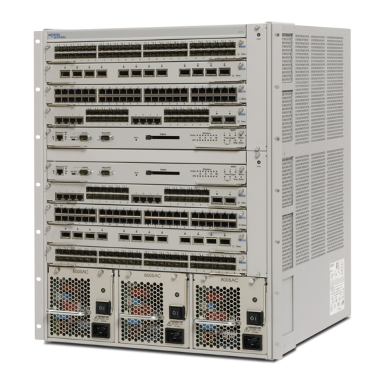
25. Slots are numbered from left to right. You can install Avaya Ethernet Routing Switch 8800/8600 interface modules in slots 1 through 4 and in slots 7 through 10. Slots 5 and 6 are reserved for Avaya Ethernet Routing Switch 8800/8600 SF/CPU modules. - Page 25 Figure 1: 8010co chassis and components The 8010co chassis has three power supply bays. The Avaya Ethernet Routing Switch 8800/8600 can be configured for AC input or DC input applications or site installations. The 8010co chassis supports the following AC power supplies: •...
-
Page 26: 8010 Chassis
27. Slots are numbered from the top down. You can install Avaya Ethernet Routing Switch 8800/8600 interface modules in slots 1 through 4 and in slots 7 through 10. Slots 5 and 6 are reserved for Ethernet Routing Switch 8800/8600 SF/CPU modules. For information about module installation, see Avaya Ethernet Routing Switch 8800/8600 Installation —... - Page 27 • 8005DI DC Important: R, RS, or 8800 modules installed in the 8006, 8010, 8010co, or 8003-R chassis may require a minimum of one 8005AC, 8005DI AC, or 8005DC power supply. Use the power calculator tool (accessible from http://www.avaya.com/support) to determine the power supply requirements for your specific module and chassis configuration.
-
Page 28: 8006 Chassis
Installation — AC Power Supply, NN46205-306 or Avaya Ethernet Routing Switch 8800/8600 Installation — DC Power Supply, NN46205-307. The 8010 chassis uses two fan trays for cooling. For information about fan trays, see Avaya Ethernet Routing Switch 8800/8600 Routine Maintenance, NN46205-312. - Page 29 • 8005DI DC Important: R, RS, or 8800 modules installed in the 8006, 8010, 8010co, or 8003-R chassis may require a minimum of one 8005AC, 8005DI AC, or 8005DC power supply. Use the power calculator tool (accessible from http://www.avaya.com/support) to determine the power supply requirements for your specific module and chassis configuration.
-
Page 30: 8003-R Chassis
Installation — AC Power Supply, NN46205-306 or Avaya Ethernet Routing Switch 8800/8600 Installation — DC Power Supply, NN46205-307. The 8006 chassis uses a single fan tray for cooling. For information about fan trays, see Avaya Ethernet Routing Switch 8800/8600 Routine Maintenance, NN46205-312. - Page 31 • 8005DI DC Caution: The 8005 power supply has different power rating. Therefore, Avaya recommends that you do not operate the Avaya Ethernet Routing Switch 8000 Series chassis with a mix of power supply model. Installation — Chassis November 2012...
-
Page 32: Power Supplies
55. The 8003-R chassis includes a single fan tray for cooling. For more information about installing and replacing a fan tray, see Avaya Ethernet Routing Switch 8800/8600 Routine Maintenance, NN46205-312. Figure 4: 8003-R chassis and components on page 31 also shows the location of customer- replaceable components in the 8003-R chassis. -
Page 33: Fan Trays And Cooling Modules
Ethernet Routing Switch 8800/8600 chassis. If you install an RS or 8800 module in the chassis, you must install the high speed cooling modules. If you do not install the high speed cooling modules, the software will not operate on the RS or 8800 module. -
Page 34: Site Requirements
For fan trays, a control or monitor circuit board in the fan tray reports temperature and the status of fan operation to the network management software. A green light emitting diode (LED) indicates correct fan operation. For information about installing fan trays, see Avaya Ethernet Routing Switch 8800/8600 Routine Maintenance, NN46205-312. - Page 35 Hardware requirements Table 3: Accessories shipped with the 8010, 8006, and 8003-R chassis Check Accessory Usage Bracket kit with Prepare the chassis for installation in an equipment rack. • Two rack-mounting brackets • Phillips-head screws Screw package Mount the chassis in an equipment rack.
- Page 36 Chassis installation fundamentals Figure 5: Items in the 8010 chassis shipping container Figure 6: Items in the 8006 chassis shipping container Installation — Chassis November 2012 Comments? infodev@avaya.com...
- Page 37 AT-compatible modem to allow dial-in access to startup configuration and diagnostics. Cables Unless you specifically order them, Avaya does not include the cables required for your network configuration in the chassis accessory package. If you need the proper cables, contact your network administrator.
-
Page 38: 8010Co Chassis
Manage network interface cables. bracket Two side cable management Manage network interface cables. brackets Figure 8: Accessories in the 8010co chassis shipping container on page 39 illustrates the accessories in the 8010co chassis shipping container. Installation — Chassis November 2012 Comments? infodev@avaya.com... - Page 39 Hardware requirements Figure 8: Accessories in the 8010co chassis shipping container Other equipment You can require items not included in the 8010co chassis accessory package. The following sections describe these items. Before you install the 8010co hardware, ensure that you obtain all the cables, tools, and other equipment you need.
-
Page 40: Successful Installation Verification
If the rack does not use threaded rail holes, you must use the supplied clip nuts with the clip nut screws. Cables Unless you specifically order them, Avaya does not include the cables required for your network configuration in the 8010co chassis accessory package. If you require the proper cables, contact your network administrator. -
Page 41: Chapter 5: 8010, 8006, And 8003-R Chassis Installation
• Inspect all items for shipping damage. If you find items that are damaged, do not install the chassis. Call the Avaya Technical Solutions Center in your area. • Verify that the items in the shipping container match those on the shipment packing list. -
Page 42: Chassis Installation Time Requirements
Figure 9: 8010, 8006, and 8003-R chassis installation procedures Chassis installation time requirements The following table lists procedures you must use to install the Avaya Ethernet Routing Switch 8800/8600 chassis and the estimated time you need to complete each procedure. Not all procedures are required for every Avaya Ethernet Routing Switch 8800/8600 system. -
Page 43: Positioning The Chassis On A Flat Surface
2. Attach rubber feet to each marked location on the bottom of the chassis. The rubber feet are optional but Avaya recommends that you use them to help keep the unit from moving. - Page 44 Positioning the rack-mounting brackets: 8006 chassis on page 44, and Figure 12: Positioning the rack-mounting brackets: 8003-R chassis on page 45. Figure 10: Positioning the rack-mounting brackets: 8010 chassis Figure 11: Positioning the rack-mounting brackets: 8006 chassis Installation — Chassis November 2012 Comments? infodev@avaya.com...
- Page 45 Mounting the chassis in an equipment rack Figure 12: Positioning the rack-mounting brackets: 8003-R chassis 2. Insert and tighten the supplied Phillips-head screws to fasten each bracket to the chassis. For more information about attaching the rack-mounting brackets, see Figure 13: Attaching the rack-mounting brackets to the 8010 chassis on page 45, Figure 14:...
- Page 46 Figure 16: Aligning the rack-mounting brackets with the equipment rack: 8010 chassis on page 47, Figure 17: Aligning the rack-mounting brackets with the equipment rack: 8006 chassis on page 47, and Figure 18: Installation — Chassis November 2012 Comments? infodev@avaya.com...
- Page 47 Mounting the chassis in an equipment rack Aligning the rack-mounting brackets with the equipment rack: 8003-R chassis page 48. Figure 16: Aligning the rack-mounting brackets with the equipment rack: 8010 chassis Figure 17: Aligning the rack-mounting brackets with the equipment rack: 8006 chassis Installation —...
- Page 48 Figure 20: Installing the 8006 chassis in an equipment rack on page 49, and Figure 21: Installing the 8003-R chassis in an equipment rack on page 49. Figure 19: Installing the 8010 chassis in an equipment rack Installation — Chassis November 2012 Comments? infodev@avaya.com...
- Page 49 Mounting the chassis in an equipment rack Figure 20: Installing the 8006 chassis in an equipment rack Figure 21: Installing the 8003-R chassis in an equipment rack Procedure job aid Table 6: Number of rack units to allocate for chassis on page 49 lists the number of rack units to allocate for each chassis.
-
Page 50: Installing The Cable Management Brackets
50, Figure 23: Loosening the rack-mounting screws: 8006 chassis on page 51, and Figure 24: Loosening the rack-mounting screws: 8003-R chassis on page 51. Figure 22: Loosening the rack-mounting screws: 8010 chassis Installation — Chassis November 2012 Comments? infodev@avaya.com... - Page 51 Installing the cable management brackets Figure 23: Loosening the rack-mounting screws: 8006 chassis Figure 24: Loosening the rack-mounting screws: 8003-R chassis 2. Slide the bracket onto the loosened screws. For more information about sliding the bracket onto the screws, see Figure 25: Sliding the bracket onto the screws: 8010, 8006, and 8003-R chassis page 51.
- Page 52 Figure 28: Securing the bracket to the chassis: 8003-R chassis on page 53. Figure 26: Securing the bracket to the chassis: 8010 chassis Figure 27: Securing the bracket to the chassis: 8006 chassis Installation — Chassis November 2012 Comments? infodev@avaya.com...
- Page 53 Installing the cable management brackets Figure 28: Securing the bracket to the chassis: 8003-R chassis Installation — Chassis November 2012...
- Page 54 8010, 8006, and 8003-R chassis installation Installation — Chassis November 2012 Comments? infodev@avaya.com...
-
Page 55: Chapter 6: 8010Co Chassis Installation
• Inspect all items for shipping damage. If you find items that are damaged, do not install the chassis. Call the Avaya Technical Solutions Center in your area. • Verify that the items in the shipping container match those on the shipment packing list. - Page 56 8010co chassis installation Figure 29: 8010co chassis installation procedures Installation — Chassis November 2012 Comments? infodev@avaya.com...
-
Page 57: Chassis Installation Time Requirements
Chassis installation time requirements The following table lists procedures you use to install the Avaya Ethernet Routing Switch 8800/8600 chassis and the estimated time you need to complete each procedure. Not all procedures are required for every Avaya Ethernet Routing Switch 8800/8600 system. - Page 58 For more information about installing the chassis, see Figure 31: Installing the 8010co chassis in a 19-in. two-post rack on page 59. Installation — Chassis November 2012 Comments? infodev@avaya.com...
-
Page 59: Installing The Cable Management Brackets
Installing the cable management brackets Figure 31: Installing the 8010co chassis in a 19-in. two-post rack 9. Make sure that the hole pairs on either side of the vertical support match horizontally. 10. Tighten each screw with a Phillips screwdriver. Installing the cable management brackets Install the cable management brackets to keep cable clusters fastened and out of the way but still accessible for maintenance. - Page 60 2. Insert eight screws through the cable management bracket and tighten into chassis. For more information, see the following figure. Installation — Chassis November 2012 Comments? infodev@avaya.com...
- Page 61 Installing the cable management brackets Figure 32: Installing cable management brackets 3. To install side cable management brackets, slide the keyed attachments into slots on either side of the card cage. Installation — Chassis November 2012...
-
Page 62: Grounding The Chassis
4. Insert fully into slot. Use the keyed attachments to lower the bracket and secure into place. Grounding the chassis Avaya recommends that you ground the 8010co chassis before you connect power cables or network cables to the switch. Prerequisites •... - Page 63 Grounding the chassis Figure 33: Rack grounding strip example Job aid The following figure shows the location of the ground studs on the 8010co chassis rear panel. Installation — Chassis November 2012...
- Page 64 The following figure shows an example of how to ground two 8010co chassis. In this example, each chassis uses three 8004DC power supplies. Your rack-grounding strip can look different or can be in a different location than the one shown in the example. Installation — Chassis November 2012 Comments? infodev@avaya.com...
- Page 65 Grounding the chassis Figure 35: Chassis and 8004DC power supply grounding example The following table describes the reference items shown in Figure 35: Chassis and 8004DC power supply grounding example on page 65. Table 8: Item description for chassis and 8004DC power supply grounding Item Description Cabinet frame or equipment rack...
- Page 66 AC power supplies. Figure 36: Chassis and AC power supply grounding example The following table describes the reference items shown in Figure 36: Chassis and AC power supply grounding example on page 66 Installation — Chassis November 2012 Comments? infodev@avaya.com...
- Page 67 Grounding the chassis Table 9: Item description for chassis and AC power supply grounding Item Description Cabinet frame or equipment rack Upper shelf chassis ground stud Upper shelf ground leads (not provided) AC equipment ground (ACEG) leads within individual lower shelf cords (x 3) Single-point ground system AWG 6 ground lead (not provided)
- Page 68 8010co chassis installation Installation — Chassis November 2012 Comments? infodev@avaya.com...
-
Page 69: Chapter 7: Switch Operations
Chapter 7: Switch operations This section describes some of the routine tasks you perform to operate the Avaya Ethernet Routing Switch 8800/8600. Powering on DC power supplies Power on the direct current (DC) power supplies to provide power to the switch. -
Page 70: Powering On Ac Power Supplies
6. Wait 1 minute. 7. On each power supply, turn the power switch to the on position. If the problem persists, contact the Avaya Technical Solutions Center. Powering on AC power supplies Power on the AC power supplies to provide power to the switch. -
Page 71: Resetting The Switch
7. Wait 1 minute. 8. On each power supply, turn the power switch to the on position. If the problem persists, contact the Avaya Technical Solutions Center. Resetting the switch Reset the switch to reboot the switch hardware without cycling power. -
Page 72: Installing Removable Flash Memory Cards In An 8895 Sf/Cpu
For more information about inserting a card, see Figure 39: Inserting a removable flash memory card: 8010co chassis on page 73 and Figure 40: Inserting a removable flash memory card: 8010, 8006, and 8003-R chassis on page 73. Installation — Chassis November 2012 Comments? infodev@avaya.com... - Page 73 Installing removable flash memory cards in an 8895 SF/CPU Figure 39: Inserting a removable flash memory card: 8010co chassis Figure 40: Inserting a removable flash memory card: 8010, 8006, and 8003-R chassis 2. Insert the card into the card receptacle. 3.
-
Page 74: Removing Removable Flash Memory Cards In An 8692 Sf/Cpu
For information about removing a card, see Figure 41: Removing a flash memory card: 8010co chassis on page 75 and Figure 42: Removing a flash memory card: 8010, 8006, 8003-R chassis on page 75. Installation — Chassis November 2012 Comments? infodev@avaya.com... - Page 75 Removing removable flash memory cards in an 8692 SF/CPU Figure 41: Removing a flash memory card: 8010co chassis Figure 42: Removing a flash memory card: 8010, 8006, 8003-R chassis 2. Pull the flash memory card out of the card receptacle. Installation —...
-
Page 76: Installing Removable Flash Memory Cards In An 8692 Sf/Cpu
3. Gently push in the card until it fits tightly in place. Removing removable flash memory cards in an 8692 SF/CPU Remove a flash memory card from the 8692 SF/CPU module to stop using it as a storage medium. Installation — Chassis November 2012 Comments? infodev@avaya.com... -
Page 77: Protecting Memory Card Files (For 8692 Sf/Cpu Only)
The 8895 SF/CPU compact flash card is not equipped with a read-write protect switch. Typically, you do not operate an Avaya Ethernet Routing Switch 8800/8600 with a write- protected memory card. Make a copy of your configuration on another memory card, write- protect the second card, and store it in a safe place. - Page 78 5. To reinsert the card, position the card with the label facing to the left and the insert arrow pointing toward the card receptacle. 6. Insert the card into the card receptacle. 7. Gently push in the card until it fits tightly in place. Installation — Chassis November 2012 Comments? infodev@avaya.com...
-
Page 79: Chapter 8: Common Procedures
1. Remove the power supply filler panels. For more information, see Avaya Ethernet Routing Switch 8800/8600 Installation — AC Power Supply, NN46205-306 or Avaya Ethernet Routing Switch 8800/8600 Installation — DC Power Supply, NN46205-307. 2. Remove the module filler panels. - Page 80 Common procedures Installation — Chassis November 2012 Comments? infodev@avaya.com...
-
Page 81: Chapter 9: Part Numbers
Chapter 9: Part numbers The following table lists Avaya Ethernet Routing Switch 8800/8600 hardware and part numbers. Part number Item Additional details DS1402001 8010 10-slot chassis Includes chassis, dual backplane, two fan trays, RS232 cable for management console, rack-mount kit, and cable management bracket kit. - Page 82 DS1411005 8010 10-slot chassis rack-mount replacement kit DS1411011 8000 series chassis filler panel/blank faceplates DS1411012 8800/8600 series console cable DS1411013 8000 series cable management bracket DS1411017-E6 8010CMHS high speed cooling module for the 8010 chassis DS1411018-E6 8006CMHS high speed cooling module...
-
Page 83: Chapter 10: Technical Specifications
Chapter 10: Technical specifications This section details the specifications for the Avaya Ethernet Routing Switch 8800/8600. Chassis weight The following table provides the chassis weight including components and cables. Table 10: Chassis weight including components and cables Chassis Weight (chassis, components, cables) -
Page 84: Rack-Mount
780 W (690 W + 90 W fans) at 100-120 VAC input voltage 850 W (760 W + 90 W fans) at 200-240 VAC input voltage Individual power ratings: 3.3 VDC @ 150 A Installation — Chassis November 2012 Comments? infodev@avaya.com... -
Page 85: Model 8005Ac Power Supply
Model 8005AC power supply Parameter Specifications (12V power includes fan power) 12 VDC @ 50 A MTBF: 246 647 hr (MIL-std 217 standard) Model 8005AC power supply This section provides power ratings for the 8005AC power supply. The following table lists the AC input power specifications. Table 15: AC input power specifications Parameter Specifications (100–120... -
Page 86: Model 8005Di Ac Power Supply
12 VDC @ 10 A, 24 A peak peak MTBF 269 000 hours (Telcordia SR-332 standard) Model 8004DC power supply This section provides power ratings for the 8004DC power supply. The following table lists the DC input power specifications. Installation — Chassis November 2012 Comments? infodev@avaya.com... -
Page 87: Model 8005Dc Power Supply
Model 8005DC power supply Table 19: DC input power specifications Parameter Specifications Input voltage – 48 VDC Input current 29 A Input VA 1.4 kVA Input power consumption 1392 W Heat dissipation (thermal/output) 1850 BTU/hour The following table lists the DC output power specifications. Table 20: DC output power specifications Parameter Specifications... -
Page 88: Model 8005Di Dc Power Supply
1462 W (1372 W + 90 W fans) Modules 3.3 V @ 150 A 12 V @ 72 A Fans 12 VDC @ 7.5 A/ 24 A peak Mean time before failure (MTBF) 108 803 hr (Bellcore TR–332 standard) Installation — Chassis November 2012 Comments? infodev@avaya.com... -
Page 89: Component Input Power
Component input power The following table shows the input power specifications for Avaya Ethernet Routing Switch 8800/8600 components. The power specifications for R, RS, and 8800 modules show the power for modules with slots containing short-range SFPs, SFP+s, or XFPs. -
Page 90: Power Supply Selection
ERS 8800/8600 documentation. Power supply selection The following table lists the power available from each power supply supported with the Avaya Ethernet Routing Switch 8800/8600. Power management identifies the available power in the chassis, called the power budget, and determines if enough power is available to operate the installed components. -
Page 91: 8010Co Chassis
8010co chassis Table 26: Maximum power available for each power supply Power supply model Card cage 3.3V maximum 12V maximum 12V fan power (amps) (amps) maximum (watts) (amps) 8004DC 57.5 8004AC @ 110VAC 42.5 8004AC @ 220VAC 42.5 8005DC 1372 8005AC @ 110VAC 1050 8005AC @ 220VAC... -
Page 92: Network Equipment Building Standard
13 123 ft. at 35°C and 45°C 6000 ft. at 55°C – 200 ft. at 55°C Storage altitude 40 000 ft Maximum airflow The maximum airflow specification for the 8010co chassis is 330 linear ft/min. Installation — Chassis November 2012 Comments? infodev@avaya.com... -
Page 93: International Regulatory Requirements
8010co chassis International regulatory requirements The 8010co chassis conforms to the following international regulatory requirements: • Electromagnetic emissions on page 93 • Electromagnetic immunity on page 93 • Safety agency certification on page 93 Electromagnetic emissions The 8010co chassis conforms to the following electromagnetic emissions standards. Table 29: 8010co electromagnetic emissions Parameter Specification... -
Page 94: 8010 Chassis
Weight (empty) 85 lb (39 kg) Weight (fully loaded) 225 lb (102 kg) Cooling system Fan trays 2 for each chassis Fans 8 for each fan tray Thermal sensors 1 for each fan tray Installation — Chassis November 2012 Comments? infodev@avaya.com... -
Page 95: Environmental Specifications
8010 chassis Parameter Specification High speed cooling 2 for each chassis modules Fans 15 for each fan tray Thermal sensors 1 for each fan tray Environmental specifications The following environmental specifications apply to the 8010 chassis. Table 33: 8010 environmental specifications Parameter Specification Operating temperature... - Page 96 Table 36: 8010 safety agency certification Parameter Specification Global basis for certification IEC 60950 current edition with all CB member deviations UL60950 Canada CSA 22.2 No. 60950 Europe EN60950 (CE Marking) Australia/New Zealand AS/NZS 3260 Mexico NOM-019-SCFI-1998 Installation — Chassis November 2012 Comments? infodev@avaya.com...
-
Page 97: 8006 Chassis
8006 chassis 8006 chassis This section provides physical, environmental, and electrical specifications for the 8006 chassis and includes the following topics: • Physical specifications on page 97 • Environmental specifications on page 97 • International regulatory requirements on page 98 Physical specifications The following physical specifications apply to the 8006 chassis. -
Page 98: International Regulatory Requirements
CISPR 22-1997 Class A FCC CFR47 Part 15, Subpart B, Class A Canada ICES-003, Issue-2, Class A Europe EN 55022-1998 Class A; EN 61000-3-2/A14, EN 61000-3-3 (CE Marking) Australia/New Zealand AS/NZS 3548:1995, Class A Installation — Chassis November 2012 Comments? infodev@avaya.com... -
Page 99: 8003-R Chassis
8003-R chassis Parameter Specification Japan VCCI-V3/97.04, Class A Taiwan CNS 13438, Class A Electromagnetic immunity The 8006 chassis conforms to the following electromagnetic immunity standards. Table 40: 8006 electromagnetic immunity Parameter Specification Global basis for certification CISPR 24:1997 Europe EN 55024:1998 Safety agency certification The 8006 chassis conforms to the following safety agency standards. -
Page 100: Physical Specifications
Table 43: Environmental specifications for the 8003-R chassis Parameter Specification Operating temperature: 0C to 40C (32F to 104F) Storage temperature: –25C to 70C (–13F to 158F) Operating humidity: 85% maximum relative humidity, noncondensing Storage humidity: 95% maximum relative humidity, noncondensing Installation — Chassis November 2012 Comments? infodev@avaya.com... -
Page 101: International Regulatory Requirements
International regulatory requirements Parameter Specification Operating altitude: 3 048 m (10 000 ft) maximum Storage altitude: 3 048 m (10 000 ft) maximum Free fall/drop: ISO 4180-s, NSTA 1A Vibration: IEC 68-2-6/34 Shock/bump: Shock/bump: International regulatory requirements The 8003-R chassis conforms to the following international regulatory requirements: •... -
Page 102: Safety Agency Certification
Table 45: Safety agency standards Parameter Specification Global basis for certification (CE Marking): IEC 60950 current edition with all CB member deviations U.S. UL60950 Canada: CSA 22.2 No. 60950 Europe: EN60950 Australia/New Zealand: AS/NZS 60950-1 Mexico: NOM-019-SCFI-1998 Installation — Chassis November 2012 Comments? infodev@avaya.com... -
Page 103: Chapter 11: Translations Of Safety Messages
Chapter 11: Translations of safety messages Class A device caution statement Caution: This device is a Class A product. Operation of this equipment in a residential area is likely to cause harmful interference, in which case users are required to take appropriate measures necessary to correct the interference at their own expense. -
Page 104: Electrostatic Discharge Caution Statement
Haut hat. Electrostatic alert: PRECAUCIÓN ESD (Descarga electrostática) Para prevenir el daño producido por una descarga electrostática, use siempre una pulsera antiestática conectada a un enchufe de descarga electrostática (ESD) al realizar el Installation — Chassis November 2012 Comments? infodev@avaya.com... -
Page 105: Laser Fiber Optic Warning Statement
Laser fiber optic warning statement mantenimiento de este producto. Asegúrese de que la pulsera antiestática haga contacto con su piel. Electrostatic alert: CUIDADO ESD Para evitar danos com descarga eletrostática, sempre use uma pulseira antiestática que esteja conectada a uma tomada de descarga eletrostática (ESD) quando estiver realizando a manutenção deste produto. -
Page 106: Lifting 8010Co Chassis Warning Statement
Risk of personal injury It requires three people to lift the 8010co chassis. To make the chassis lighter, remove the modules and power supplies before you lift it. Warning: AVERTISSEMENT Risques de blessure corporelle Installation — Chassis November 2012 Comments? infodev@avaya.com... - Page 107 Lifting 8010co chassis warning statement Trois personnes sont nécessaires pour soulever le châssis 8010co. Pour alléger le châssis, retirez les modules et les alimentations avant de le soulever. Warning: WARNUNG Verletzungsrisiko Es sind 3 Personen notwendig, um das Chassis des 8010co anzuheben. Entfernen Sie vor dem Anheben die Module und die Netzteile, um so das Gewicht des Chassis zu reduzieren.
- Page 108 Translations of safety messages Installation — Chassis November 2012 Comments? infodev@avaya.com...
-
Page 109: Chapter 12: Customer Service
Chapter 12: Customer service Visit the Avaya Web site to access the complete range of services and support that Avaya provides. Go www.avaya.com or go to one of the pages listed in the following sections. Getting technical documentation To download and print selected technical publications and release notes directly from the Internet, go to www.avaya.com/support. - Page 110 Customer service Installation — Chassis November 2012 Comments? infodev@avaya.com...