Advertisement
Advertisement

Related Manuals for Pentax DSI-200 Series

Summary of Contents for Pentax DSI-200 Series
- Page 1 Pentax DSI-200 Series Frequency Inverter User's Manual...
- Page 2 Foreword Thank you for using the Pentax DSI-200 series of high-performance vector inverter. This guide explains how to properly use DSI-200 series inverter. Before using (installation, operation, maintenance, inspection, etc.), be sure to carefully read the instructions. Understanding of product safety precautions before using this product.
- Page 3 1. Definition of security In this manual, safety issues the following two categories: Warning: Due to the dangers posed against the required operation, may result in serious injury and even death. Caution: Due to the dangers posed against the required operation, may lead to moderate harm or minor injuries, and damage to the equipment.
- Page 4 Otherwise there will be unexpected danger. There shall be circuit breaker between the inverter and power supply. Otherwise, there may be fire. Make sure the power is disconnected prior to the connection. Otherwise there will be danger of electric shock. ...
- Page 5 Caution If the parameter identification is required, pay attention to the danger of injury arising from the rotating motor. Otherwise accident may occur. Do not change the factory settings at will. Otherwise it may damage the equipment. During the Operation Warning ...
- Page 6 2.2 Nameplate specification Variable Frequency Inverter MODEL: DSI-200-004G3/5K5P3 POWER: 4Kw / 5.5 Kw INPUT: 3PH 400V~ 10.5A 50Hz/60Hz OUTPUT: 3PH 0-400V~ 9A 50HZ/60HZ Pentax Inverter Figure 2-2 Nameplate 2.3 DSI-200 Inverter product series Power Input Output Match Model current A...
- Page 7 Item Specification P type: 0.5Hz/100% 1:100 (SVC) 1:1000 (FVC) Speed range Speed control ±0.5%(SVC) ±0.02%(FVC) accuracy Torque control ±5%(FVC) accuracy G type: 150% rated current 60sec; 180% rated current 3sec Overload capacity P type: 120% rated current 60sec; 150% rated current 3sec Torque boost Auto-torque boost;...
- Page 8 Item Specification Timing control timing control function: setting time range: 0.0min~6500.0min Multi-motor 2sets of motor parameter, can realize 2motors switching switch control Multi-threading Support multiple fieldbus: Modbus, RS85, CAN open, CAN bus support link Multi-encoder Support differential, open collector, rotary transformer support Multi threading bus support...
- Page 9 Item Specification Differential PG card, open collector PG card, OC input PG Optional parts card Indoor, without direct sunlight, no powder, corrosive gas, Application site combustion air, oil dust, water steam, water drop or salt etc. Altitude level Less than 1000m Environme -10℃~+40℃(During 40℃~50℃,please reduce capacity Environment...
- Page 10 Figure 2-5 Keyboard Operator Outline and Installation Dimensional Drawings Figure 2-6 Keyboard Operator Outline and Installation Dimensional Drawings 2.5.1 Mechanical Outsize (mm) Install Model Type hole DSI-200-K40G1 DSI-200-K75G1 Ф5.7 DSI-200-1K5G1 DSI-200-2K2G1 DSI-200-K75G3...
- Page 11 Outsize (mm) Install Model Type hole DSI-200-1K5G3 DSI-200-2K2G3 Ф4.7 DSI-200-004G3/5K5P3 2.5.2 Operation panel shape 2.5.3 Shape and size of the panel tray 2.6 The daily maintenance and maintenance of the inverter 2.6.1 Daily Maintenance In order to avoid faults of the frequency converter, ensure the normal operation of equipment and prolong the service life of the frequency converter, daily maintenance is necessary for the frequency converter.
- Page 12 2) Whether or not vibration is generated during motor operation 3) Whether the inverter installation environment has changed 4) Whether the inverter cooling fan is working properly 5) Whether the inverter overheating Daily cleaning: 1) Always keep the drive in a clean state. 2) Effectively remove the dust on the surface of the inverter to prevent dust into the inverter inside.
- Page 13 that within 2 years through a power, power time of at least 5 hours, the input voltage must be slowly raised to the rated voltage regulator. 2.7 Guide for Selection of Brake Components (*): Figure 2-1 is the guide data, the user can choose according to the actual situation of different resistance and power, (but the resistance must not be less than the recommended value in the table, the power can be large.) The choice of braking resistor The actual application of the motor power generation to determine the power, and system...
- Page 14 3. Mechanical and Electrical Installation 3.1 Mechanical Installation 3.1.1 Installation environment: 1) Ambient temperature: The ambient temperature has a great influence on the life of the inverter. Do not allow the operating temperature of the inverter to exceed the permissible temperature range (-10 ℃ ~ 40 ℃). 2) Mount the inverter on the surface of the flame retardant and attach it to the mounting bracket vertically with screws.
- Page 15 Figure 3-1 DSI-200 installation diagram...
- Page 16 Unit installation: When the inverter power is not greater than 22kW cannot consider the A size. When greater than 22kW, A should be greater than 50mm. Up and down installation: Install the thermal insulation baffle when the inverter is installed up and down Installment size Power level ≤15kW...
- Page 17 Recommended Recommended Empty open Recommend output side Recommended input side (MCCB) Model main control circuit Contactor Main circuit Circuit wire Wire mm lead wire mm DSI-200-2K2G3 DSI-200- 004G3/5K5P3 DSI-200- 5K5G3/7K5P3 3.2.2 Connect with peripheral devices Figure 3-2 Connection to peripheral devices - 17 -...
- Page 18 3.2.3 Instructions for the use of external electrical components Name Setting station Function Input the front When the downstream device is over current, disconnect Air switch of the loop the power supply Empty and The inverter should be operated up and down, and the between the Contactor frequency converter should be avoided by the contactor...
- Page 19 fig. 3-3a) Terminal Function description symbol Ground terminal R, S, T: Connected to the grid three-phase AC power supply R、S、T R, S: Connect to the grid single-phase AC power supply U、V、W Connect three-phase (380V or 220V) AC motor Filter capacitor DC side voltage positive terminal DC braking resistor can be connected to + 3.3.2 Terminals of Control Loop: 485+ 485-...
- Page 20 3.4 Standard Wiring Diagram Pentax DSI-200 VFD Figure 3-5 Standard wiring diagram Terminal Function and description name Multi-function digital input S1~S5 +10V-GND +10V power supply for this unit (current: 10mA) Analog input, voltage (0~10V) / current (0~20mA) can be AI1-GND...
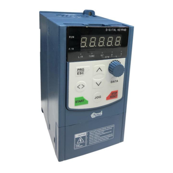
- Page 21 Terminal Function and description name 485 communication port, 485 differential signal positive and negative terminals, standard 485 communication interface, 485+、485- please use twisted pair or shielded cable 4. Operation Display and Application Examples Operation and display interface 4.1.1 Panel diagram Increment Key Menu (Program) Key Decrement Key...
- Page 22 Key name Key function In the shutdown display interface and run the display interface, you can cycle to select the display < > Shift key parameters; modify the parameters, you can select the parameters of the modified bit Start the AC drive when using the operating panel control mode.
- Page 23 4.2 Function code view, modify method description DSI-200 the operation panel of the inverter adopts the three-level menu structure to set the parameters and so on. The third level menu is: Function parameter group (level menu) → Function code (Ⅱ level menu) → Function code setting value (Ⅲ grade menu) The operation flow is shown in Figure 4-2 Figure 4-2 Three-level menu operation flow chart Note: When operating in a three-level menu, press PRG or ENTER to return to the...
- Page 24 Figure 4-3 When operating in Level III menus, if the parameter does not include a flashing digit, then it is not possible to modify that parameter. There are two possible reasons for this: 1)The function parameter you have selected is read-only。 2)The displayed function parameter cannot be modified while the AC drive is in the RUNNING status.
- Page 25 4.3.2 Inverter commissioning sub-flow chart 1 - 25 -...
- Page 26 UN key on the keyboard panel to start the self-learning operation of the motor parameters. 5. Function Parameters Table PP-00 is set to a non-zero value, that is, the parameter protection password is set. In the function parameter mode and the user changes the parameter mode, the parameter menu must enter the password correctly and cancel the password.
- Page 27 5.1 basic function data 5.1 Data and specifics Functi Name Set Range default Alteration Code P0 Basic Function Group 0: No speed sensor vector control (SVC) ★ P0-01 Motor 1 control mode 1: Speed sensor vector control (FVC) 2: V / F control 0: Operation panel instruction channel ☆...
- Page 28 0: relative to maximum frequency Auxiliary frequency source B ☆ P0-05 1: Relative to frequency source Reference object selection Auxiliary frequency source B ☆ P0-06 100% 0%~150% command range Functi Name Set Range default Alteration Code Bit: frequency source selection 0: Main frequency source A 1: main and auxiliary operation results (operation relationship...
- Page 29 Frequency reference lower 0.00 Hz to frequency upper ☆ P0-14 0.00Hz limit limit P0-12 Carrier frequency Model ☆ P0-15 0.8kHz~12.0kHz determined Carrier frequency adjusted ☆ P0-16 0:no 1:yes with temperature Acceleration time 1 Model ☆ P0-17 0.00s~65000s determined Model ☆ P0-18 Deceleration time 1 0.00s~65000s...
- Page 30 Bit: Operation panel command Bind frequency source selection 0: no binding 1: Digital setting frequency 2: AI1 (Note: J6 jumper) 3: AI2 The run command is tied to 4: AI3 ☆ the main frequency source 5: High-speed pulse input setting P0-27 0000 (S5)
- Page 31 Mutual inductive Auto-tuning 0.1mH~6553.5mH ★ P1-09 dependent No-load current Auto-tuning ★ 0.01A~P1-03 P1-10 dependent Encoder pulses ★ P1-27 1024 1~65535 A/B phase sequence of ABZ 0: Forward ★ P1-30 incremental encoder 1: Reserve Encoder wire-break fault 0.0: no operation ★ P1-36 detection 0.0s...
- Page 32 0: Function code P2-10 setting 1: AI1 2: AI2 3: AI3 4: High-speed pulse input setting (S5) Torque limit source in speed ☆ P2-09 5: communication given control 6: MIN (AI1, AI2) 7: MAX (AI1, AI2) 1-7 option full scale corresponds to P2-10 Digital setting of torque limit ☆...
- Page 33 Max. torque coefficient of field ☆ P2-21 50~200% 100% weakening area Regenerative power limit 0: Disabled ☆ P2-22 selection 1: Enabled Model ☆ P2-23 Regenerative power limit 0~200% dependent P3 V/F Control Parameters 0: Straight line V / F 1: multi-point V / F 2: square V / F 3: 1.2 Power V / F V/F curve setting...
- Page 34 0: digital setting (P3-14) 1: AI1 (Note: J6 jumper) 2: AI2 3: AI3 4: High-speed pulse input Voltage source for V/F setting (S5) ☆ P3-13 separation 5: multi-segment instructions 6: Simple PLC 7: PID 8: communication given Note: 100.0% corresponds to the motor rated voltage Digital setting of voltage for ☆...
- Page 35 Frequency rise threshold ★ P3-26 0~50Hz during voltage limit Function Name Set Range default Alteration Code P4 Input Terminals ★ P4-01 S2 function selection ★ P4-02 S3 function selection ★ P4-03 S4 function selection ★ P4-04 S5 function selection - 35 -...
- Page 36 Function Name Set Range default Alteration Code ☆ P4-10 S1~S5 filter time 0.010s 0.000s~1.000s 0: two lines 1 Terminal control mode 1: two lines 2 ★ P4-11 2: three lines 1 3: three lines 2 Terminal UP/DOWN rate ☆ P4-12 1.00Hz/s 0.001Hz/s~65.535Hz/s AI curve 1 min.
- Page 37 AI3 filter time ☆ P4-27 0.10s 0.00s~10.00s Pulse min. input ☆ P4-28 0.00kHz~P4-30 0.00kHz Corresponding percentage of ☆ P4-29 pulse min. input 0.0% -100.0%~100.0% Pulse max. input ☆ P4-30 50.00kHz P4-28~100.00kHz Corresponding percentage of ☆ P4-31 100.0% -100.0%~100.0% Pulse max. input ☆...
- Page 38 Function 0: active high Name Set Range default Code Alteration 1: active low Bit: S1 ★ 0: No output P4-38 S1~S5 active mode selection 1 Ten: S2 00000 1: The inverter is running Hundred places: S3 2: fault output (fault stop) Thousands of bits: S4 HDY function selection ☆...
- Page 39 34: zero current state 35: Module temperature arrives 36: Output current is exceeded 37: Lower frequency arrival (shutdown also output) 38: Alarm output (continued) 39:Motor over temperature warning 40: This run time arrives 41: fault output (for free stop fault), and under voltage is not output Function Name...
- Page 40 0: Positive logic 1: anti logic Bit: HDO (HDY) ☆ P5-22 active mode selection 00000 Ten: RO1A Hundred places: RO2A Thousands of bits: DO Million: reserved Function Name Set Range default Alteration Code Start/Stop Control 0: Direct start 1: Catching a spinning motor Start mode ☆...
- Page 41 Stop mode 0: Decelerate to stop ☆ P6-10 1: Coast to stop DC injection braking 2 start ☆ P6-11 frequency 0.00Hz 0.00Hz~max frequency(P0-10) DC injection braking 2 delay ☆ P6-12 time 0.0s 0.0s~100.0s DC injection braking 2 level ☆ P6-13 0%~100% DC injection braking 2 active ☆...
- Page 42 0000 ~ FFFF Bit00: Operating frequency 1 (Hz) Bit01: Set frequency (Hz) Bit02: Bus voltage (V) Bit03: Output voltage (V) Bit04: Output current (A) Bit05: Output power (kW) LED display running Bit06: Output torque (%) ☆ P7-03 parameters 1 Bit07: S terminal input status Bit08: HDO output status Bit09: AI1 voltage (V) Bit10: AI2 Voltage (V)
- Page 43 0000 ~ FFFF Bit00: Set frequency (Hz) Bit01: Bus voltage (V) Bit02: S input status Bit03: HDO output status Bit04: AI1 voltage (V) Bit05: AI2 voltage (V) ☆ P7-05 LED display stop parameters Bit06: AI3 voltage (V) Bit07: Count value Bit08: Length value Bit09: PLC stage Bit10: Load speed...
- Page 44 Model ☆ P8-05 Acceleration time 3 0.0s to 6500.0s dependent Model ☆ P8-06 Deceleration time 3 0.0s to 6500.0s dependent ☆ P8-07 Acceleration time 4 0.0s to 6500.0s 0.0s ☆ P8-08 Deceleration time 4 0.0s to 6500.0s 0.0s ☆ P8-09 Frequency jump 1 0.00 Hz to max.
- Page 45 0.0% to 100.0% (max. ☆ P8-31 Detection width of frequency 1 0.0% frequency) 50.00 Hz ☆ P8-32 Detection of frequency 2 0.00 Hz to max. frequency 0.0% to 100.0% (max. ☆ P8-33 Detection width of frequency 2 0.0% frequency) 0.0% to 300.0% (rated motor ☆...
- Page 46 Function FACTORY Name Set Range Alteration Code code ☆ P9-00 Motor overload protection 0, 1 ☆ P9-01 Motor overload protection gain 0.20 to 10.00 1.00 Motor overload pre-warning ☆ P9-02 50% to 100% coefficient 0 (no over voltage stall) to ☆...
- Page 47 ● P9-17 Frequency upon 3rd fault ● P9-18 Current upon 3rd fault ● P9-19 Bus voltage upon 3rd fault ● P9-20 DI state upon 3rd fault ● P9-21 DO state upon 3rd fault ● P9-22 AC drive state upon 3rd fault ●...
- Page 48 Frequency selection for ☆ P9-54 continuing 0 to 4 to run upon fault 0.0% to 100.0% (max. ☆ P9-55 Backup frequency upon fault 100.0% frequency) Power dip ride-through ★ P9-59 function 0 to 2 selection Threshold of power dip ride ★...
- Page 49 ☆ PA-10 PID differential limit 0.00% to 100.00% 0.10% ☆ PA-11 PID reference change time 0.00s to 650.00s 0.00s ☆ PA-12 PID feedback filter time 0.00s to 60.00s 0.00s ☆ PA-13 PID output filter time 0.00s to 60.00s 0.00s PA-14 Reserved ☆...
- Page 50 ☆ PC-08 Reference 8 -100.0% to 100.0% 0.0% ☆ PC-09 Reference 9 -100.0% to 100.0% 0.0% ☆ PC-10 Reference 10 -100.0% to 100.0% 0.0% ☆ PC-11 Reference 11 -100.0% to 100.0% 0.0% ☆ PC-12 Reference 12 -100.0% to 100.0% 0.0% ☆...
- Page 51 Para. Para. Name Setting Range Default Property Acceleration/deceleration ☆ PC-23 time of 0 to 3 simple PLC reference 2 Running time of simple 0.0s (h) to 6553.5s ☆ PC-24 0.0s (h) reference 3 Acceleration/deceleration ☆ PC-25 time of 0 to 3 simple PLC reference 3 Running time of simple 0.0s (h) to 6553.5s...
- Page 52 Running time of simple 0.0s (h) to 6553.5s ☆ PC-38 0.0s (h) reference 10 Acceleration/deceleration ☆ PC-39 time of 0 to 3 simple PLC reference 10 Running time of simple 0.0s (h) to 6553.5s ☆ PC-40 0.0s (h) reference 11 Acceleration/deceleration ☆...
- Page 53 0.001 to 65.535 Ω (AC drive Auto- power ≤ 55 kW) ★ A2-07 Rotor resistance tuning 0.0001 to 6.5535 Ω (AC dependent drive power > 55 kW) 0.01 to 655.35 mH (AC Auto- drive power ≤ 55 kW) ★ A2-08 Leakage inductive reactance tuning 0.001 to 65.535 mH (AC...
- Page 54 1-7 option full scale, corresponding to A2-48 digital settings Digital setting of torque limit in ☆ A2-48 0.0% to 200.0% 150.0% speed control 0: Function code P2-10 setting 1: AI1 (Note: J6 jumper) 2: AI2 3: AI3 4: High-speed pulse input setting (S5) Torque limit source in speed ☆...
- Page 55 weakening area 0: Disabled 1: Enabled in whole process 2: Enabled at constant ☆ A2-60 Regenerative power limit selection speed 3: Enabled during deceleration Model ☆ A2-61 Regenerative power upper limit 0.0% to 200.0% dependent ★ A2-62 Motor 2 control mode 0 to 2 Motor 2 acceleration/deceleration ☆...
- Page 56 ☆ AI curve 5 inflexion 1 input A6-10 A6-08 to A6-12 -3.00 V Corresponding percentage of AI ☆ A6-11 -100.0% to 100.0% -30.0% curve 5 inflexion 1 input ☆ AI curve 5 inflexion 2 input A6-12 A6-10 to A6-14 3.00 V Corresponding percentage of AI ☆...
- Page 57 factory ☆ AC-10 AI3 measured voltage 2 -10.00 to 10.000 V corrected factory ☆ AC-11 AI3 displayed voltage 2 -10.00 to 10.000 V corrected factory ☆ AC-12 AO1 target voltage 1 -10.00 to 10.000 V corrected factory ☆ AC-13 AO1 measured voltage 1 -10.00 to 10.000 V corrected factory...
- Page 58 5.2 monitoring parameters Commun Para. No. Para. Name Display Range ication Group dO: Monitoring Parameters dO-00 Running frequency 0.01Hz 7000H dO-01 Frequency reference 0.01Hz 7001H dO-02 Bus voltage 0.1V 7002H dO-03 Output voltage 7003H dO-04 Output current 0.01A 7004H dO-05 Output power 0.1kW 7005H...
- Page 59 dO-32 Viewing any register address value 0.01Hz 701FH dO-34 Motor temperature 7020H dO-35 Target torque 1℃ 7022H dO-36 Resolver position 0.1% 7023H 6. Parameter Description Function Description Application code Refers to open loop vector control, suitable for Set 0:non-speed the usual high-performance control occasions, a Sensor vector control drive can only drive a motor.
- Page 60 Pic 6-1 Select the input channel for the given frequency of the drive. AI1, AI2, AI3, high-speed pulse setting (S5), multi-segment instructions, PLC, PID, and so on. Notes: P0-23 is "digital setting frequency stop memory selection", P0-23 is used to select whether the correction amount of frequency is memorized or cleared when the inverter is stopped.
- Page 61 -100.00% to 100.00%, 100.00% refers to the relative maximum frequency P0-10 percentage. DSI-200 support two kinds of host computer communication: Modbus, CANlink, these two kinds of communication cannot be used at the same time. The CANlink protocol is always valid Auxiliary frequency Factory default source...
- Page 62 source A. If the range is selected relative to the main frequency source, the range of the auxiliary frequency source Frequency A changes Frequency source combination mode Factory default selection Frequency source selection 0: Main frequency source A 1: Main and auxiliary operation result (calculation relationship is determined by ten bits) 2: Main frequency source A and auxiliary frequency source B switching...
- Page 63 Set range 0.00~max frequency(The frequency source selection mode is valid for the digital setting) When the frequency source is selected as "digital setting", the function code value is the frequency of the inverter. Motor rotation Factory default direction P0-09 Set range 0:same direction 1:opposite direction By changing the function code, you can change the motor wiring without changing the motor...
- Page 64 Running Factory 0.00Hz frequency lower default P0-14 limit offset Set range 0.00Hz~upper frequency P0-12 When the frequency command is lower than the lower limit of P0-14, the inverter can be stopped, run at the lower limit frequency or run at zero speed. What mode of operation can be used through P8-14 (setting frequency lower than lower frequency operation mode) Set acceleration time 1 Factory default Motor type confirmation...
- Page 65 Group four:P8-07、P8-08; Combined frequency of Factory default 0.00Hz auxiliary frequency source P0-21 Set range 0.00Hz~max frequency P0-10 This function code is valid only when the frequency source is selected as the master and slave operation. When the frequency source is the main auxiliary operation, P0-21 is used as the bias frequency, and the result of the main and auxiliary operation is superimposed as the final frequency setting value, so that the frequency setting can be more flexible.
- Page 66 Set range 0:operating frequency 1:set frequency This parameter is valid only when the frequency source is digital. Used to determine the keyboard ▲, ▼ key or terminal UP / DOWN action, the way to amend the set frequency, that is, the target frequency is based on the operating frequency increase or decrease, or in the set frequency based on the increase or decrease.
- Page 67 Closely related. 0.01A ~ 655.35A Motor 1 Model ( AC motor frequency≤ P1-03 rated determined 55kW) current Motor 1 0.01Hz ~max Model P1-04 rated determined frequency frequency Motor 1 Model 1rpm ~ 65535rpm P1-05 rated rmp determined Asynchron 0.001Ω ~ 65.535Ω ous motor Model ( AC motor frequency≤...
- Page 68 0: A phase advance when motor is running forward (B phase advance incrementa 0: Forward when motor reverses) P1-30 l AB 1: Reverse 1: When the motor is running Phase forward B phase advance (the sequence motor reverses the A phase ahead) Used to set the encoder break Speed fault detection time, when set to...
- Page 69 Figure 6-4 PI Parameter diagram By setting the speed factor and the integration time of the speed regulator, you can adjust the velocity dynamic response characteristics of the vector control. Increase the proportional gain, reduce the integration time, can speed up the dynamic response of the speed loop.
- Page 70 5:Communication settings 6:MIN(AI1,AI2) 7:MAX(AI1,AI2) Speed setting mode of torque upper limit Factory default 150.0% digital setting P2-10 Set range 0.0%~200.0% Speed control mode Torque upper limit command channel selection (power Factory default generation) 0:P2-10 1:AI1 2:AI2 3:AI3 High speed pulse input setting(S5) P2-11...
- Page 71 Torque adjustment Factory default 2000 proportional gain P2-15 Set range 0~20000 Torque adjustment Factory default 1300 integral gain P2-16 Set range 0~20000 Vector control current loop PI adjustment parameters, the parameters in the asynchronous machine after the self-learning will automatically get, generally do not need to modify. Need to be reminded that the current loop integral regulator, not the use of integral time as a dimension, but directly set the integral gain.
- Page 72 2: square V / F. Suitable for fans, pumps and other centrifugal load. 3 ~ 8: between the linear VF and square VF VF relationship between the curve. 10: VF complete separation mode. At this time the output frequency of the inverter and the output voltage are independent of each other, the output frequency is determined by the frequency source, and the output voltage is determined by P3-13 (VF separation voltage source).
- Page 73 Multipoint VF Factory 0.00Hz frequency point P1 default P3-03 Set range 0.00Hz~P3-05 Multi point VF voltage Factory 0.0% point V1 default P3-04 Set range 0.0%~100.0% Multi point VF Factory 0.00Hz frequency point P2 default P3-05 Set range P3-03~P3-07 Multi point VF voltage Factory 0.0% point V2...
-
Page 74: Table Of Contents
Fb:Rated motor operating frequency Figure 6-6 multi point V/F Curve setting diagram VF Over-excitation Factory default P3-10 gain Set range 0~200 In the inverter deceleration process, the over-excitation control can inhibit the bus voltage rise, to avoid over-voltage failure. The greater the over-excitation gain, the stronger the suppression effect. -
Page 75: Factory Default
Separation is generally used in induction heating, inverter power supply and torque motor control and other occasions. When selecting VF separation control, the output voltage can be set via function code P3 - 14, or from analog, multi-step instructions, PLC, PID or communication reference. When the non-digital setting is used, each set of 100% corresponds to the rated voltage of the motor. - Page 76 Figure 6-7 V/F Separation diagram P4 Group Input Terminal EV510 series inverter comes standard with seven multi-function digital input terminals (where S5 can be used as high-speed pulse input terminal), three analog input terminals, two relay outputs, one optocoupler collector output. Function code Name Factory default...
- Page 77 Function Description value (RJOG) Terminal UP When the frequency is given by the external terminal, the frequency is increased and decremented. The frequency source is set to Terminal DOWN When the digit is set, adjust the set frequency up and down. The inverter blocks the output, and the motor stop process is not Freely stop controlled by the inverter, This way with.
- Page 78 Function Description value selection terminal Used to switch between different frequency sources. Frequency source Depending on the frequency source selection function code switching (P0-07) is set when setting between two frequency sources UP/DOWN set When the frequency is given as a digital frequency reference, this terminal can clear the terminal UP / DOWN or Keyboard 0 (terminal、...
- Page 79 Function Description value Immediate DC When the terminal is valid, the inverter will switch directly to braking the DC braking state External fault When the external fault normally closed signal into the normally closed inverter, the inverter reported failure EF and shutdown. input Frequency If the function is set to active, the frequency converter does...
- Page 80 Function Description value Speed control / The frequency converter is switched between torque control torque control and speed control mode. When the terminal is inactive, the switching inverter operates in the mode defined by A0-00 (speed / torque control mode), and the terminal is switched to another mode. When the terminal is active, the inverter stops at the fastest speed, and the current is at the set current limit during the stop.
- Page 81 Multi - step instructions 4 PC-04 Multi - step instructions 5 PC-05 Multi - step instructions 6 PC-06 Multi - step instructions 7 PC-07 Multi - step instructions 8 PC-08 Multi - step instructions 9 PC-09 OFF Multi - step instructions 10 PC-10 Multi - step instructions 11 PC-11...
- Page 82 external terminal. Note: For convenience of explanation, the S1, S2, and S2 terminals of the multi-function input terminals S1 to S10 are selected as external terminals. That is, by setting the value of P4-00 ~ P4-02 to select the functions of S1, S2 and S2 three terminals. For details, please refer to the setting range of P4-00 ~ P4-09.
- Page 83 Figure 6-9 three wires model 2 As shown in the figure above, the control mode in K1 closed state, K2 disconnect the inverter forward. K2 closed inverter reverse; K1 off, the inverter stops running. 2: three-wire control mode 1: This mode S3 to enable the terminal, the direction of the control by the S1, S2 Function setting as follow shows:...
- Page 84 Terminal function P4-00 RUNNING choose Terminal function Forward and reverse P4-01 choose direction of operation. Terminal function Three - wire operation P4-02 choose control Figure 6-11 Three - wire control mode 2 As shown in the figure above, the control mode is in the SB1 button closed state, press the SB2 button inverter running, K disconnect the inverter forward, K closed inverter reverse;...
- Page 85 The function code is used to set the relationship between the analog input voltage and the set value it represents. When the analog input voltage is greater than the set "maximum input" (P4-15), the analog voltage is calculated according to the "maximum input"; Similarly, when the analog input voltage is less than the set "minimum input"...
- Page 86 AI Curve 3 minimum input Factory 0.0% corresponds to setting default P4-24 Set range -100.00%~100.0% Factory AI Curve 3 maximum input 4.00V default P4-25 Set range P4-23~10.00V AI Curve 3 maximum input Factory 100.0% corresponds to setting default P4-26 Set range -100.00%~100.0% Factory AI3 Input filter time...
- Page 87 Set range 1: curve 1 (2 point, see P4-13~P4-16) 2: curve 2 (2 point, see P4-18~P4-21) 3: curve 3 (2 point, see P4-23~P4-26) 4: curve 4 (4 point, see A6-00~A6-07) 5: curve 5(4 point,see A6-08~A6-15) AI2 curve choose(1~5,same as above) Hundred AI3 curve choose(1~5,same as above)...
- Page 88 Used to set the delay time for the inverter to change when the S-terminal status changes. Currently only S1, S2, S3 with the delay time to set the function. S1~S5 Terminal valid Factory 00000 mode selection 1 value S1 Terminal valid status setting 0:Active high 1:active low P4-38...
- Page 89 Function description value stop) Frequency level Please refer to the description of function codes P8- detection FDT1 output 19 and P8-20. Please refer to the description of function codes P8- Frequency reached 19 and P8-20. Zero speed operation When the inverter is running and the output (non output when stop frequency is 0, the ON signal is output.
- Page 90 Function description value Lower frequency When the operating frequency reaches the lower arrival limit frequency, the ON signal is output. In shutdown (Not output when mode, the signal is OFF. stopped) Under voltage status When the inverter is in the undervoltage condition, output the ON signal is output.
- Page 91 Lower frequency When the operating frequency reaches the lower arrival limit frequency, the ON signal is output. The signal is (Shutdown also output) also ON in the shutdown state When the inverter fails, and the fault processing mode for the continued operation, the inverter alarm Warning output output.
- Page 92 Pulse or analog output 0.0% to 100.0% of the Function value corresponding function settings 0~The maximum output frequency corresponds Motor speed to the speed Output current 0.0A~1000.0A output voltage 0.0V~1000.0V Output torque (actual -2 times the motor rated torque~2 times the motor value) rated torque HDP output max...
- Page 93 bits HDY Effective state selection 0:Positive logic 1:Anti-logic Set range tens RO1A Valid status settings(0~1,as RO2A Valid status settings(0~1,as above) hundred Thousands / keep above) million Defines the output logic of the output terminal HDO, relay 1, and relay 2. 0: Positive logic, digital output terminal and corresponding common terminal are connected to active state and are disconnected to invalid state;...
- Page 94 Factory Start frequency hold time 0.0s default P6-04 Set range 0.0s~100.0s To ensure the motor torque at start-up, set the appropriate starting frequency. In order to fully establish the magnetic flux when starting the motor, it is necessary to start the frequency for a certain time.
- Page 95 The output frequency is incremented or decremented by line. 1:S curve acceleration and deceleration A (static) The output frequency is incremented or decremented according to the S curve. The S- curve is used in places where gentle start or stop is required, such as elevators, conveyor belts, etc.
- Page 96 Setting 0.0s~36.0s Range DC braking to stop start frequency: The inverter starts DC braking stop when the running frequency decreases to the value set in this parameter in the process of deceleration to stop. DC braking to stop delay time: When the running frequency decreases to DC braking to stop start frequency in P6-11, the inverter stops output for a period of time and then starts DC injection braking.
- Page 97 0 0 0 0 ~ FFFF Running frequency 1 (Hz) Setting frequency (Hz) Bus voltage (V) Output voltage (V) Output current (A) Output power (kW) Output torque (%) 15 14 13 12 11 10 S input state (V) HY1 output state Setting AI1 voltage (V) Range...
- Page 98 PID feedback PLC stage High-speed pulse reference (kHz) Running frequency 2(Hz) Remaining running time AI1 voltage before correction (V) AI2 voltage before correction (V) AI3 voltage before correction (V) 0 0 0 0 ~ Setting Range FFFF 15 14 13 12 11 10 Motor speed Current power-on time (Hour)
- Page 99 Frequency reference (Hz) Bus voltage (V) S input state HDO output state AI1 voltage (V) AI2 voltage (V) AI3 voltage (V) Count value 0 0 0 Settin 0 ~ FFFF Range 15 14 13 12 11 10 Length value PLC stage Load speed PID reference High speed pulse input reference (kHz)
- Page 100 Setting 0. 0s~6500.0s Range DSI-200 provides totally four groups of acceleration/deceleration time for selection ( P0-17、P0-18 and the above three groups of acceleration/deceleration time). These four groups of acceleration/deceleration time define are same, please reference P0-17、P0-18 of instruction. By using the different combination of multi-function digital input terminal S, we can switch over the selection of 4 groups four groups of acceleration/deceleration time.
- Page 101 Setting Range 0.00s~3000.0s In the process of setting the inverter forward and reverse, the switchover time in the output 0Hz is shown in figure 6-15. Figure 6-15 Forward/Reverse run switch over dead-zone time Forbid reverse run Factory default selection P8-13 Setting Range 0:...
- Page 102 Accumulative power-on time Factory default threshold P8-16 Setting Range 0h~65000h Multi-function digital terminal HDO output ON signal when accumulative power-on time of the AC drive (P7-13) exceeds value set in FP-16. Set the cumulative time to reach 100 hours: P8-16 = 100. Then, when the accumulated power time reaches 100 hours, the inverter output faulty of FU29.
- Page 103 Figure 6-16 FDT electrical level function Detection width of target frequency Factory 0.0% reached default P8-21 Setting Range 0.00~100%max. frequency When the run frequency of the inverter is in a certain range of the target frequency, multi- function terminal HDY outputs the ON signal. This parameter is used to set the detection range of the frequency arrival, which is the percentage relative to the maximum frequency.
- Page 104 Figure 6-17 schematic diagram of frequency arrival detection Frequency jump function valid Factory during acceleration/deceleration default P8-22 1:valid 0:invalid Setting Range The function code is used to set whether the frequency jump is valid during acceleration and deceleration. If set to be valid, when the running frequency is in the frequency jump range, the actual running frequency will jump over frequency jump boundary.
- Page 105 Switch over frequency of 0.00Hz acceleration time 1 and Factory default P8-25 acceleration time 2 Setting Range 0.00Hz~max. frequency Switch over frequency of 0.00Hz deceleration Factory default P8-26 time 1 and deceleration time 2 Setting Range 0.00Hz~max. frequency This function is valid when the motor is selected as motor 1 and is not switched over through the S terminal to select the acceleration and deceleration time.
- Page 106 Frequency detection value 2 Factory default 50.00Hz (FDT2) P8-28 Setting Range 0.00Hz~max. frequency Frequency detection Factory 5.0% hysteresis 2 default P8-29 Setting Range 0.0%~100.0%(FDT2 electric level) The frequency detection function is exactly the same as the function of FDT1. Please refer to the relevant instructions of FDT1 with the function code P8-19 and P8-20.
- Page 107 Factory Zero current detection level 5.0% default P8-34 Setting Range 0.0%~300.0%(rated motor current) Factory Zero current detection delay 0.10s default P8-35 Setting Range 0.00s~600.00s When the output current of the inverter is less than or equal to the detection level of the zero current and the delay time exceeds the zero current detection delay time, the multi- function terminal HDY outputs the ON signal.
- Page 108 Figure 6-22 Output current limit. Factory Detection level of current 1 100.0% default P8-38 0.0%~300.0%( rated motor current ) Setting Range Factory Detection width of current 1 0.0% default P8-39 0.0%~300.0%( rated motor current ) Setting Range Factory Detection level of current 2 100.0% default P8-40...
- Page 109 Figure 6-23 Current detection Timing function Factory default P8-42 Setting Range 0:invalid 1:valid Running time setting Factory default channel 1:AI1 0:set by P8-44 P8-43 2:AI2 3:AI3 Setting Range (100% of analog input corresponds to the value of P8-44) Running time Factory default 0.0Min P8-44...
- Page 110 When the temperature of the inverter radiator reaches the temperature, the multi-function terminal HDO output "module temperature overheat" of ON signal. Cooling fan working Factory default mode P8-48 1 : Working 0 : Working during drive running Setting Range continuously The parameter sets cooling fan operation mode, when the value set to 0, inverter in the running state makes fan to work, When the drive stops, the fan works if heatsink temperature is above 40°C and stops if heatsink temperature is below 40°C.
- Page 111 current for 1 minutes, the alarm indicates motor overload fault; 150% * (P9-01) * motor rated current for 60 minutes, then the alarm indicates motor overload. The user needs to set the value of P9-01 correctly according to the actual overload capacity of the motor.
- Page 112 0:Current running frequency 1:Frequency reference Setting Range 2:Frequency upper limit 3:Frequency lower limit 4:Backup frequency for abnormality Backup frequency for Factory default 100.0% P9-55 abnormality Setting Range 0.0%~100.0%(max. frequency) When a fault occurs during the inverter running and the method of handling is set to continue running, the frequency inverter displays A** and runs at the frequency determined by the P9-54.
- Page 113 Figure 6-24 action during instantaneous power failure Load lost protection Factory default P9-63 Setting Range 0:invalid 1:valid Load lost detection level Factory default 10.0% P9-64 0.0%~100.0%(Rated motor current ) Setting Range Load lost detection time Factory default 1.0s P9-65 Setting Range 0.0s~60.0s If load lost protection function is valid, when output current of the inverter falls below detection level (P9-64) for longer than time set in...
- Page 114 vector control with speed sensor . When detected motor speed exceeds reference frequency and the excess is larger than the value of P9-67 for longer than time set in P9-68, the inverter warns FU43 and acts according to the faulty protection set. If overspeed detection time is 0.0S, it will cancel over speed detection.
- Page 115 Figure 6-25 process PID schematic block diagram PID given source Factory default selection 0: PA-01 setting 1:AI1 2:AI2 3:AI3 PA-00 4: high speed pulse input setting(S5) Set range 5: Communication given 6: multi-segment instructions PID given value factory default 50.0% PA-01 Set range 0.0%~100.0%...
- Page 116 Reaction: When the PID feedback signal is less than a given amount, the inverter output frequency drops. Such as the tension of the tension control occasions. This function is affected by the direction of the multi-function terminal PID action (function 35), the need to pay attention.
- Page 117 Set range 0. 0%~100.0% When the deviation between the PID set amount and the feedback amount is less than PA-09, the PID stops the adjustment operation. In this way, the output frequency is stable when the deviation between the given feedback and the feedback is small, which is effective for some closed-loop control PID Differential Factory default...
- Page 118 PID Parameter switching Factory default 20.0% deviation 1 PA-19 Set range 0.0%~PA-20 PID Parameter switching Factory default 80.0% deviation 2 PA-20 Set range PA-19~100.0% In some applications, a set of PID parameters cannot meet the needs of the entire operation process, the need for different conditions using different PID parameters.
- Page 119 Figure 6-27 shows the function of the PID initial value PID Integral attribute Factory default Integral separation 0: invalid 1: valid PA-25 Set range Whether to stop the integration after outputting the limit value 0: Continue to score 1: stop to score Integral separation If the integral separation is valid, when the multi-function digital S integral is suspended (function 22) is valid, the integral PID integral of the PID stops operation, and PID is only...
- Page 120 Factory PID Stop operation default PA-28 Stop non-operation Set range Stop operation PB Group Wobble, length and count Wobble function suitable for textile, chemical fiber and other industries, as well as the need for traverse, winding function of the occasion. Wobble function refers to the inverter output frequency, set the frequency as the center of the upper and lower swing, the operating frequency in the time axis of the track as shown in Figure 6-28, the swing amplitude is set by PB-00 and PB-01.
- Page 121 Swing setting mode Factory default PB-00 0: relative to center frequency 1: relative to maximum Set range frequency Use this parameter to determine the reference for the swing. 0: relative center frequency (P0-07 frequency source), for the variable swing system.
- Page 122 The above function codes are used for fixed length control. The length information needs to be collected by the multi-function digital input terminal. The number of pulses sampled by the terminal is divided by the number of pulses per minute PB-07, and the actual length PB-06 can be calculated. When the actual length is greater than the set length PB-05, the multi-function digital HDO outputs the "length arrival"...
- Page 123 instructions. Multi command 0~15 Factory default 0.0% PC-00~ PC-15 Set range -100.0%~100.0% Multi-segment instructions can be used in three cases: as a frequency source, as VF separation of the voltage source, as the process PID set the source. In the three applications, the dimension of the multi-segment instruction is the relative value, the range is -100.0% ~ 100.0%, which is the percentage of the relative maximum frequency when it is the frequency source.
- Page 124 0: single run end stop The inverter to complete a single cycle after the automatic shutdown, you need to give a run command to start again. 1: the end of a single run to maintain the final value After the inverter completes a single cycle, it automatically keeps the last running frequency and direction.
- Page 125 Set range 0~3 Simple PLC third run Factory default 0.0s(h) time PC-24 Set range 0.0s(h)~6553.5s(h) Easy PLC paragraph 3 acceleration / Factory default PC-25 deceleration time Set range 0~3 Simple PLC 4th run time Factory default 0.0s(h) PC-26 Set range 0.0s(h)~6553.5s(h)...
- Page 126 Simple PLC ninth run Factory default 0.0s(h) time PC-36 Set range 0.0s(h)~6553.5s(h) Easy PLC paragraph 9 acceleration / Factory default PC-37 deceleration Set range 0~3 Simple PLC tenth run Factory default 0.0s(h) time PC-38 Set range 0.0 s(h)~6553.5s(h) Easy PLC paragraph 10 acceleration / Factory default PC-39...
- Page 127 Easy PLC paragraph 14 acceleration / Factory default PC-47 deceleration Set range 0~3 Simple PLC fifteenth run Factory default 0.0s(h) time PC-48 Set range 0.0s(h)~6553.5s(h) Easy PLC paragraph 15 PC-49 acceleration / Factory default deceleration Set range 0~3 Simple PLC run time Factory default unit PC-50...
- Page 128 terminals should be used in conjunction with A0-00 to achieve speed and torque control switching. When the speed control / torque control switching terminal is invalid, the control mode is determined by A0-00. If the speed control / torque control switching is valid, the control mode is equivalent to the value of A0-00.
- Page 129 DSI-200 provides five groups of corresponding relationship curve, in which three groups of curves for the linear relationship (2-point correspondence), 2 groups of 4 points corresponding to any curve, the user can use P4-13 ~ P4-27 function code and A6 group function Code to set.
- Page 130 Factory Torque control deceleration time 0.00s default A0-08 Set range 0.00s~65000s In the torque control mode, the difference between the output torque and the load torque of the motor determines the speed change rate of the motor and the load. Therefore, the motor speed may change rapidly, resulting in excessive noise or mechanical stress.
- Page 131 Random PWM depth 0: Random PWM invalid A5-03 Setting Range 1~10 : PWM Carrier frequency random depth Set random PWM, you can monotonous harsh motor sound becomes more soft, and can help reduce the external electromagnetic interference. When the random PWM depth is set to 0, the random PWM is disabled.
- Page 132 Corresponding percentage of Factory default 60.0% A6-05 curve 4 inflexion 2 input Set range -100.0%~100.0% AI curve 4 max. input Factory default 10.00V A6-06 Set range A6-06~10.00V Corresponding percentage of Factory default 100.0% Curve 4 max. input A6-07 Set range -100.0%~100.0% AI curve 4 min.
- Page 133 Figure 6-31 Curve 4 and Curve 5 Schematic Curve 4 and curve 5 should be noted that the minimum input voltage curve, the inflection point 1 voltage, inflection point 2 voltage, the maximum voltage must be increased in turn. AI curve selection P4-33, used to determine the analog input AI1 ~ AI3 how to choose from 5 curves.
- Page 134 parameters through the communication value for the host computer monitoring. The communication address is 0 × 7000 ~ 0 × 7040 Where d0-00 to d0-31 are the run and stop monitoring parameters defined in P7-03 and P7-04. d0-15 PID setting Display range 0~65535 d0-16...
- Page 135 Increase the setting of P0-15 (carrier frequency) by 1.0 kHz Too loud motor noise gradually. Note that increase in carrier frequency will result in an increase in the leakage current of the motor. Check whether torque upper limit is small. If yes, please Insufficient motor Increase the setting of P2-10 (digital setting of torque upper torque...
- Page 136 Error Solution Motor oscillation 1. Increase the setting of P3-11 (V/F oscillation suppression gain) during running by 10 gradually. The permissible maximum setting here is 100. Over current during 1. Decrease the setting of P3-01 (torque boost) by 0.5% gradually. start 1.
- Page 137 Customized torque boost or Adjust the customized torque boost V/F curve is not or V/F curve. appropriate. The spinning motor is Enable the catching a spinning motor started. function or start the motor after it stops. View historical fault records. If the current value is far from the over The AC drive suffers current level, find interference...
- Page 138 Ensure that current limit is enabled (P3-19). The over current stall The setting of current limit level (P3- prevention 18) is too large. Adjust it parameters are set between 120% and 150%. improperly. The setting of current limit gain (P3- 20) is too small.
- Page 139 Deceleration time is too Increase deceleration time. short. Braking unit and braking Install braking unit and braking resistor are resistor. not installed. Ensure that the voltage limit function is enabled (P3-23 ) The setting of voltage limit (F3-22) is too large.
- Page 140 Check resistance between motor wires. Motor winding is damaged. Replace motor is winding is damaged. The cable connecting the Check for wiring errors and ensure Output AC drive the output cable is connected FU13 and the motor is abnormal. properly correct wiring.
- Page 141 The hall is abnormal. Replace the hall. Current detection FU18 The drive board is failure Replace the drive board. abnormal. Motor parameters are not Set motor parameters correctly set according to nameplate. according to nameplate. Motor auto-tuning times Check the cable connecting AC drive Motor self- out.
- Page 142 Load is too heavy or Reduce load or check motor and locked-rotor occurs on mechanical conditions Pulse-by- Motor. pulse FU40 current limit fault The AC drive power Replace a drive of larger power class. class is small. Motor Motor switchover via ...
- Page 143 Control board or operating panel is faulty. Rectifier bridge is damaged. Wire between drive board Re-plug the 30-core cable and control board is in poor Related components on control board are damaged "510-H" is The motor or motor cable is displayed while short circuited to ground.
- Page 144 not rotate after drive and motor is normal. the AC drive runs. Restore the factory parameters and re-set the following parameters properly: Encoder parameters Motor ratings, such as rate Related AC drive and motor frequency and rated motor parameters ...
- Page 145 Contact the agent Load fluctuates. Check whether the relay or contactor cable is loose. FU17 is Check whether the relay or The pre-charge relay or detected upon contactor is not contactor is faulty. power-on or Check whether 24 V power Closed.
- Page 146 EV510 Definition of Communication Data Address The drive supports four communication protocols (Modbus-RTU, CANopen, CANlink, PROFIBUS-DP).The user programmable card and point-to-point communication are derivation of CANlink protocol. Host computer can implement control such as monitoring and parameter viewing and modification on The AC drive through their protocols.
- Page 147 For groups P0 to PF and A0 to AF, the high 16 bits of the communication address indicate the group number and the low 16 bits indicate the parameter number in the group. Example: Communication address of P0-16 is F010H, where F0H represents group P0 and 10H is the hexadecimal data format of serial number 16 in the group.
- Page 148 I.2 Non-Parameter Data Group d monitoring parameters, AC drive fault information Status data (read and AC drive running status only) DSI-200. Non-Parameter Control Control Control commands, communication setting values, AO1 information and AC drive running status Data parameters parameters control, AO2 control, high-speed pulse (FMP) output Control commands, communication setting values, DO (write-only) control and parameter initialization...
- Page 149 AC Drive's 1: Forward run 3000H 2: Reverse run 3: Stop 2. Control Parameters The control parameters include control command, communication setting values, AO1 control, AO2 control, high-speed pulse (FMP) output control and parameter initialization. ● Control commands When P0-02 (command source selection) is set to 2 (serial comms.), you can Implement control such as start/stop of the AC drive by using communication address.
- Page 150 Communication reference Communication setting values include data set via communication such as frequency reference, torque limit, V/F separation voltage, PID reference and PID feedback. Communication address is 1000H. The range is -10000−10000 and corresponding value range is -100.00% to 100.00%. ●...
- Page 151 Parameter initialization This function is required when you need to perform parameter initialization on the drive by using host computer. If PP-00 (User password) is set to a non-zero value, pass password verification first. Host computer performs parameter initialization within 30s after password verification is successful. Communication address password...
- Page 152 Modbus Communication Protocol The drive provides RS485 communication interface and supports Modbus-RTU communication protocol so that the user can implement centralized control, such as setting running commands and function codes, and reading running status and fault information of the AC drive, by using a PC or PLC. J.1 Agreement content This protocol defines content and format of transmitted messages during serial communication, including master polling (or...
- Page 153 A device is the master (can be a PC, a PLC or an HMI) and initiates communication to perform parameter read or write operations on slaves. The other devices (slaves) provide data to respond to query or operations from the master. At the same moment, either the master or the slave transmits data and the other can only receive data.
- Page 154 "query/command" from the master. For a broadcast message sent by the master, the slaves need not return a response. Data Format The drive supports reading and writing of word-type parameters only. Reading command is 0x03 and writing command is 0x06. It does not support reading and writing of bytes or bits.
- Page 155 If the slave detects a communication frame error or reading/writing failure is caused by other reasons, an error frame will be returned as follows:...
- Page 156 The frame format is described in the following table. Frame header START Greater than the 3.5-byte transmission idle time Communication address : 1 to 247 Slave address (ADR) 0: Broadcast address 03:Read slave parameters Command code (CMD) 06: Write slave parameters It is the internal parameter address of the AC drive, expressed Function code address H in hexadecimal format.
- Page 157 CRC Check In Modbus-CRC mode, a message includes a CRC-based error- check field. The CRC field checks content of entire message. The CRC field is two bytes, containing a 16-bit binary value. The CRC field is calculated by transmitting device, and then added to message.
- Page 158 The CRC simple function is as follows: unsigned int crc_chek value(unsigned char *data value, unsigned char length){ unsigned int crc value=0xFFFF; int i; while(length--) crc_value^=*data_value++; for(i=0;i<8;i++) if(crc_value&0x0001) =(crc_value>>1) else ^0xa001;{ crc_value=crc_value>>1; return(crc_value);...
- Page 159 Definition of Communication Parameter Addresses Read and Written Parameters Function parameters can be read and written (except those which cannot be changed because they are only for the factory use or for monitoring). Parameter group No. and parameter identifying No. are used to express parameter address.
- Page 160 Therefore, in communication mode, users can change values of certain parameters in RAM rather than storing the setting. ● For groups P parameters, users only need to change high order F of the function code address to 0. For groups A parameters, users only need to change high order A of the function code address to 4.The function code addresses are expressed as follows: ●...
- Page 161 1004 Output current 1014 Feedback speed, unit: 0.1Hz 1005 Output power 1015 Remaining running time 1006 Output torque 1016 AI1 voltage before correction 1007 Running speed 1017 AI2 voltage before correction 1008 S input indication 1018 AI3 voltage before correction 1009 HDO output indication 1019...
- Page 162 0001: Forward run 0002: Reverse run 0003: Forward jog 2000 0004: Reverse jog 0005: Coast to stop 0006: Decelerate to stop 0007: Fault reset Read AC drive state (read-only): Command Word Address Command Word function 0001: Forward RUN 3000 0002: Reverse RUN 0003: Stop Parameter lock password check:(If "8888H"...
- Page 163 2003 0~7FFF indicate 0%~100% Pulse output control (write-only) Command Address Command Content 2004 0~7FFF indicate 0%~100% AC drive fault description AC Drive AC Drive Fault Information Fault Address 0000: No fault 0014: Encoder/PG card 0001: Reserved fault 001D: Accumulative 0002:Over current 000D:Power output phase power-on time reached during...
- Page 164 Group Communication Parameter Description Baud rate Factory default 6005 Bit:MODBUS Baud rate 0:300BPS 5:9600BPS Pd-00 1:600BPS 6:19200BPS Set range 2:1200BPS 7:38400BPS 3:2400BPS 8:57600BPS 4:4800BPS 9:115200BPS This parameter is used to set transmission speed between host computer and AC drive. Note that baud rate of host computer must be the same as that of AC drive.
- Page 165 local address is set to 0 (that is, broadcast address), AC drive can only receive and execute broadcast commands of host computer, but will not respond to host computer. Modbus Response Factory default delay Pd-03 Set range 0~20ms This parameter sets interval between AC drive completing receiving data and AC drive sending data to host computer.
- Page 166 Bit: MODBUS 0: Non-standard MODBUS protocol 1: Standard MODBUS protocol Setting Range Ten: Profibus-DP 0: PPO1 format Pd-05 = 1: Select the standard Modbus protocol. Pd-05 = 0: When reading a command, the number of bytes returned by the slave is one byte greater than the standard Modbus protocol.
- Page 167 Pentax DSI-200 Series Frequency Inverter جاده مخصوص کرج، روبروی رنگ هاویلوکس، پالک کیلومتر Viale dell'Industria, 1 44566111 :تلفن 37040 Veronella (VR) Italy 44566114 :فاکس Tel. +39 0442 489 500 www. dieselsaz.com Fax +39 0442 489 510 Trading@ dieselsaz.com www.pentax-pump.com com@pentax-pumps.it...