Comdial DX-80 Technical Manual
Hide thumbs
Also See for DX-80:
- Installation & maintenance manual (352 pages) ,
- Installation and maintenance manual (350 pages) ,
- Manual (106 pages)
Table of Contents
Advertisement
Quick Links
Advertisement
Table of Contents
Troubleshooting

Related Manuals for Comdial DX-80


Summary of Contents for Comdial DX-80
- Page 1 DX-80 Technical Manual Volume I Installation & Maintenance...
- Page 2 DX-80, PC-DBA, and DET are trademarks of Comdial Corporation. All other product names are trademarks of their respective owners. First Edition October, 2003...
-
Page 3: Table Of Contents
DX-80 Installation & Maintenance TABLE OF CONTENTS Introduction Chapter 1. Overview 1.1 System Technology ................... 11 1.2 Configuration ..................... 13 1.2.1 KSU1 Components ..................... 13 1.2.2 KSU2 Components ..................... 13 1.2.3 Voice Processing Modules ................... 14 1.2.4 Configuration Table ....................15 1.3 Key Service Unit .................... - Page 4 1.15.10 MTBF (Mean-Time Between Failure) Data ............38 Chapter 2. Installing the DX-80 2.1 Installation Overview ..................39 2.2 Site Planning ...................... 40 2.3 Tools and Supplies .................... 41 2.4 Preparing the Main Distribution Frame .............. 42 2.4.1 Assembling the MDF ....................42 2.4.2 KSU Components and Installation ................42...
- Page 5 DX-80 Installation & Maintenance 2.18 Power-up Initialization (Cold Start) ..............67 Chapter 3. Maintenance and Trouble Shooting 3.1 System Maintenance ..................71 3.2 Technical Problem Solving ................71 3.3 Maintenance Utilities ..................76 3.3.1 Loading PC-DBA software ................... 77 3.4 Entering into PC-DBA Maintenance ..............77 3.5 Communicating with the System ...............
- Page 6 4.10 Digits Passed Inband to the Voice Mail in an Overflow 1 Condition .................... 114 4.11 Digits Passed Inband to the Voice Mail in an Overflow 2 Condition ....115 4.12 Digits Passed Inband to the Voice Mail in a Re-Route Condition ....116 Index Comdial October, ‘03...
- Page 7 DX-80 Installation & Maintenance REVISION HISTORY Version Changes Date Initial version October-31-2003 October, ‘03 Comdial...
- Page 8 This Page Intentionally Left Blank viii Comdial October, ‘03...
- Page 9 DX-80 Installation & Maintenance Introduction This manual describes how to install the DX-80 system and to maintain it after you have installed it. This manual is intended to provide: • basic knowledge of the components of the DX-80 hardware and software •...
- Page 10 In this instance, we use the “~ “ character to indicate the range. For example, 05-01-1~3-001~100 tells you to enter: • 05 • 01 • a 1, 2, or 3, • a three-digit number that falls in the 001 to 100 range. Comdial October, ‘03...
-
Page 11: Chapter 1. Overview
DX-80 Installation & Maintenance 1. OVERVIEW The Comdial DX-80 is a fully digital hybrid key telephone system. The DX-80 uses “loop start” central office (telephone company) line interfaces, and a mix of analog and digital extension ports to provide office communications and connectivity to the Public Switched Telephone Network (PSTN). - Page 12 Attendant and on-board modem. 100 hours storage and 100 mailboxes. 7272 4 port expansion to 7271C or 7270C. The maximum system configuration is 16 CO lines, 56 extensions (48 digital and 8 analog) and 8 voice processing channels. Comdial October, ‘03...
-
Page 13: Configuration
DX-80 Installation & Maintenance 1.2 Configuration The Comdial DX-80 platform is comprised of one full-featured key telephone model and two modular KSUs (Key Service Units). Several modules are available for enhanced system applications and con- figuration expandability. 1.2.1 KSU1 COMPONENTS The CPM (Central Processor Module) is installed inside of KSU1 to the 408M ribbon cable J4 (also labeled “To CPM”). -
Page 14: Voice Processing Modules
The DX-80 provides several voice processing (or voice mail) options. The optional voice processors that you can add to the DX-80 are fixed system resources that do not require peripheral device ports (analog or digital). This significant advantage means that the DX-80 VP options can be added to any DX-80 configuration without “port loss”... -
Page 15: Configuration Table
1.3 Key Service Unit The DX-80 Key Service Unit (KSU) is a modular flat-pack design. Two KSU’s (KSU1 and KSU2) may be equipped to achieve the total system capacity of 16 CO lines, 56 extensions (48 digital and 8 analog) and 8 Voice Processing channels. -
Page 16: Power Supply
CPM (system call processing). 1.4 Power Supply The power supply circuitry of the DX-80 incorporates a linear design AC transformer with a choice of input voltage. The voltage selector switch is shipped set for 117vac applications; you can also set this switch for 230vac applications. -
Page 17: Cpm (Central Processor Module)
1.5 CPM (Central Processor Module) The CPM module is equipped standard in KSU1. This board contains all circuitry required to control the fully equipped DX-80. The system uses the CPM to perform all digital voice switching and call processing data switching. -
Page 18: Ksu1 Component)
• JP30 Internal/External—JP30 is used to select the Music Channel 1 source. The DX-80 provides a synthesized music source for music on hold, in applications where no music source is available. - Page 19 DX-80 Installation & Maintenance Figure 1-3 KSU1 shown with cover – CPM and APM4 removed (408M exposed) APM4 ribbon CPM ribbon COM4 ribbon cable cable cable four loop start eight digital power failure CO line ports ports port The 408M is equipped with a heartbeat LED that indicates processing activity on the PCB. (The 408M peripheral processor is operating when the heartbeat LED is flashing.) The KSU1 operation LED...
-
Page 20: Ksu Ii Component)
APM4 installed inside of KSU2. Each CO line circuit incorporates over-voltage protection, ring detector, loop detector, loop/pulse-dial relay, current sink circuit, coupling/isolation transformer (impedance 600:600), hybrid circuit, CODEC & filter, polarity guard circuit and Radio Frequency noise filter. Comdial October, ‘03... -
Page 21: Apm4 (Analog Port Module - 4 Circuits)
RJ-11 connectors along the bottom edge of the module. 1.8 APM4 (Analog Port Module - 4 Circuits) The APM4 provides four separate analog device ports. This allows the DX-80 to support auxiliary office equipment such as fax machines, PC/FAX modems, and analog telephones (single line tele- phones). - Page 22 When an APM4 is installed via J2 or J3, it takes the place of DPM8 modules that might be installed in those locations. Therefore APM4 modules installed using J2 or J3 will reduce the total number of Digital Port Modules (DPM8) possible. Comdial October, ‘03...
-
Page 23: Dpm8 (Digital Port Module - 8 Circuits)
DX-80 Installation & Maintenance 1.9 DPM8 (Digital Port Module - 8 Circuits) The DPM8 module expands the DX-80 system capacity of digital ports DET (Digital Executive Tele- phones) and DSS consoles. Each digital port is comprised of a proprietary octal ASIC transceiver. -
Page 24: Com4 (Central Office Module - 4 Circuits)
CO lines. Since one COM4 may be installed in KSU1 and one COM4 may be installed in KSU2, you can expand the DX-80 system CO line capacity to support up to 16 CO lines. Figure 1-7 COM4 (Central Office Module - 4 Port) -
Page 25: Mdm (Modem Module)
You can service the system, using PC-DBA and a modem in your PC, to place a call to the site where the DX-80 is installed. Note: If one of the voice processing systems are installed, routing to the modem extension is automated. Otherwise, the person who answers this data call must transfer the call to extension 199. -
Page 26: Aam (Automated Attendant Module)
The Automated Attendant Module is a self contained integrated module that enables automatic answering of selected CO lines and a single-level menu for greeting callers and routing them to DX-80 system destinations. The AAM can handle all call traffic or act as a backup to the primary answering system attendant. - Page 27 DX-80 Installation & Maintenance The display also provides a visual reference to call progress and call duration, as well as time and date information. The display enables the user to send and receive visual advisory and callback messages. Users may select from six pre-programmed messages (i.e., “IN A MEETING,” “OUT OF OFFICE”), or they may create a custom message.
-
Page 28: Dss (Direct Station Selection) Console
Overview 1.14 DSS (Direct Station Selection) Console he DSS console is a digitally interfaced component of the DX-80. It connects to the system via any available digital port (408M/E or DPM8 digital port). The DSS is equipped with 60 programmable buttons. -
Page 29: Specifications
DX-80 Installation & Maintenance 1.15 Specifications 1.15.1 CURRENT DRAW Use this chart to calculate the Amphour requirements of the DX-80 system based upon its configu- ration. This information is typically used to apply UPS battery requirements. Component Current Draw Quantity... -
Page 30: System Criteria And Capacity
Any number of CO lines may be programmed for DISA operation. (AAM required for operation.) System Attendants 1 Attendant + 1 alternate per tenant group Tenant Groups UCD/Hunt Groups: Members per group: Group Types: UCD or Voice Announce Hunting Method: Linear, All Ring or Distributed Comdial October, ‘03... - Page 31 DX-80 Installation & Maintenance Voice Mail Groups 1 per Tenant (uses 1 UCD Group per VM system) Members (ports) Integration Method Digital (ICD Voice) and In-band (for other) VM message waiting #96 + station number to turn VM button LED on.
- Page 32 DET ”########” (eight astericks) System Reminder Alarm 8 time settings per tenant group Station Alarm 1 per station repeating or one time Ring Schemes Distinctive Ring Tones 8 per station External Call Forward via extension call forward settings Comdial October, ‘03...
-
Page 33: Electrical Data
DX-80 Installation & Maintenance 1.15.3 ELECTRICAL DATA Electrical Specifications AC Power source Dedicated 117/230vac + 15%, 47-63Hz single phase Power consumption 1.5A maximum @ 120vac (180 watts) Power Supply fuse AC input: 2A 250v DC output: 1A 125v Idle Channel Noise... -
Page 34: Unit (Component) Detail
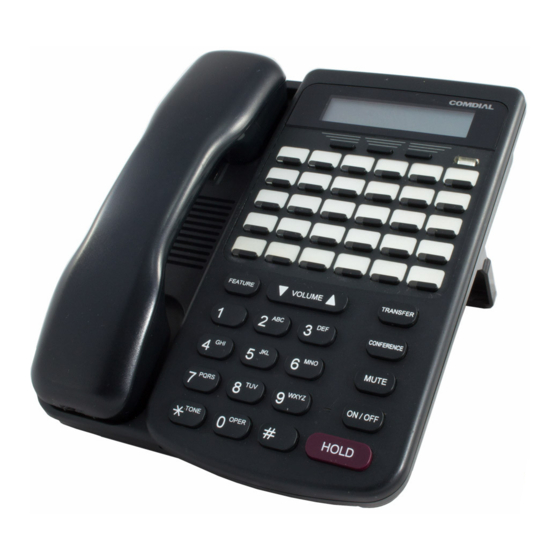
234 mm 9.36 in. 0.3Kg 188 mm 7.52 in. 64.5 mm 2.58 in. 7260-00 DET – BK 230 mm 9 in. 1.7Kg Digital Executive Telephone – Black 182 mm 7.25 in. (LCD Speakerphone) 140 mm 5.5 in. Comdial October, ‘03... -
Page 35: Wiring Data
DX-80 Installation & Maintenance Unit Specifications 7266-00 DSS Console – Black 241 mm 9.5 in. 1.7Kg 202 mm 8 in. 93 mm 3.75 in. 1.15.6 WIRING DATA Maximum Cable Length DET (distance measures in linear feet of 26 AWG - 255m (850 ft.) cable from KSU to DET) 24 AWG - 425m (1416 ft.) -
Page 36: Regulatory Data
Scheme 5 follows ring cadence of Ring Scheme selected Scheme 6 follows ring cadence of Ring Scheme selected Scheme 7 -SLT bell- follows ring cadence of Ring Scheme selected Distinctive 1 Distinctive 2 Distinctive 3 Distinctive 4 Comdial October, ‘03... - Page 37 DX-80 Installation & Maintenance Audible Signals Intercom Ringing: Scheme 0 1 second On, 3 seconds Off Scheme 1 1 second On, 3 seconds Off Scheme 2 300ms On, 400ms Off, 300ms On, 4 seconds Scheme 3 follows ring cadence of Ring Scheme selected...
-
Page 38: Mtbf (Mean-Time Between Failure) Data
Use the total from step 1 in place of the variable (1 ³ )x(109) = MTBF hours “x” in the formula at the right to calculate MTBF for this system configuration. Comdial October, ‘03... -
Page 39: Chapter 2. Installing The
DX-80 Installation & Maintenance 2. INSTALLING THE DX-80 Proper installation of the Comdial DX-80 is essential to assure optimum system operation. You must follow these procedures to reduce system problems resulting from improper installation and to reduce the potential of experiencing problems while bringing the DX-80 on-line. -
Page 40: Site Planning
(such as those generated by heavy motors, copy machines and some kitchen appliances). CAUTION The DX-80 system must be installed in a climate controlled environ- ment. This equipment cannot function in environments above 95 degrees Fahrenheit ambient temperature. -
Page 41: Tools And Supplies
26 AWG gauge minimum. 2.3 Tools and Supplies Assemble the correct supplies and tools to install the Comdial DX-80. • Use UTP (Unshielded, Twisted-Pair) three or four pair (recommended) cable to run from the MDF to all extension terminals (DETs, DSS consoles, and analog devices). DETs only need one twisted pair to operate. -
Page 42: Preparing The Main Distribution Frame
Installing the DX-80 2.4 Preparing the Main Distribution Frame The MDF is the point at which the KSU, terminal equipment, CO lines, and miscellaneous equipment connect to one another. It is extremely important that you make the connections carefully and accu- rately. -
Page 43: Mounting The Ksu
DX-80 Installation & Maintenance 2.4.3 MOUNTING THE KSU Follow these instructions to mount the KSU. 1. Select a suitable location for the KSU1 considering that the expansion (KSU2) may be installed at the same time or sometime in the future. KSU1 and KSU2 may be mounted such that they are side-by-side or mounted one above the other. -
Page 44: Ksu Wiring
“MDF”) is recommended whenever possible to allow for maximum serviceability. 2.5.1 MDF Whenever you extend the various ports of the DX-80 to the MDF, you must extend modular-ended cables from the KSU module port to the MDF connection block. You have many choices when com- pleting these connections;... -
Page 45: No Mdf
DX-80 Installation & Maintenance When you are finished with the KSU wiring, you can individually isolate each port of the DX-80 system for independent maintenance needs. Terminate the wiring in place onto a 66M1-50 – connector block. Extend ports from this connector block to station cables using standard jumper wire. -
Page 46: Typical Mdf Installation
Installing the DX-80 2.6 Typical MDF Installation The following example install illustrates a two-cabinet installation using the MDF installation method. Dedicated AC Outlet. (Dedicated means that “Station” this AC Cables from outlet has telephones no other equipment DX-80 DX-80 connected... -
Page 47: Ksu Components
408M/E. The 408M/E is also the interface point for the various add-on modules of the DX-80 system. All peripheral modules connect to the DX-80 via the 408M/E. See the following diagram for a reference to the various interface connectors. -
Page 48: Replacing A 408M Or 408E
408M/E. Modules are mounted using standoff posts. Two standoff post sizes are used in the DX-80. The APM4 modules must be installed using the nickel color 2.5 cm standoffs. All other modules use brass color 1.5 cm standoffs. Proper use of standoff is imperative to assure proper system operation. -
Page 49: Adding A Dpm8
2.7.4 ADDING A DPM8 You can add two DPM8 modules to each KSU of the DX-80 system. These modules expand the DX- 80 system capacity to a maximum of 24 digital ports in each KSU, for a total of 48 total digital ports. -
Page 50: Adding An Apm4
2.8 Adding an APM4 You can add one APM4 to KSU1 and two APM4’s to the KSU2. These modules expand the DX-80 system capacity to a maximum of eight analog ports in each KSU (16 total analog ports when used in both KSU1 &... - Page 51 DX-80 Installation & Maintenance APM4 408M APM4 Extension Number Matrix Per Installed Location KSU Connector Extension numbers Extension Numbers Notes used in KSU1 in KSU2 APM4 Connector 149,150,151,152 153,154,155,156 KSU1 analog ports are standard (SLOT 4) J2 Extension 109,110,111,112 133,134,135,136...
- Page 52 Circuit boards are susceptible to damage caused by electrostatic discharge. You must keep this in mind as you handle the circuit boards. Refer to Comdial publication IMI01-005, Handling of Electrostatically Sensitive Components, for details. 4. Remove the APM4 module from the packaging and locate the four nickel-color standoffs pack- aged with the module.
-
Page 53: Adding A Com4
2.9 Adding a COM4 You can add one COM4 to KSU1 and one COM4 to the KSU2. These modules expand the DX-80 system CO line interface capacity to a maximum of eight CO line ports in each KSU (16 total CO line ports when used in KSU 1 &... - Page 54 Refer to Comdial publication IMI01-005, Handling of Electrostatically Sensitive Components, for details. 4. Comdial recommends installing the COM4 closest to the 408M/E. This means you must tem- porarily remove the CPM and then reposition the CPM above the COM4 once you have installed the COM4 (in KSU1).
-
Page 55: Adding An Mdm
DX-80 Installation & Maintenance 2.10 Adding an MDM You can add one MDM to KSU1. The MDM allows you to remotely access to the DX-80 database programming and maintenance functions using PC-DBA. Note: The MDM does not provide access to the DX-80 In-Skin Voice Mail/AA. -
Page 56: Adding An Aam
You can add one AAM to the KSU1. The AA Module adds automated attendant functionality to the DX-80 system with 10 integrated announcements. The AAM does not provide voice mail functions. For details on how to program the AAM and its announcements, refer to the DX-80 Technical Manual, Volume II, Programming. - Page 57 Circuit boards are susceptible to damage caused by electrostatic discharge. You must keep this in mind as you handle the circuit boards. Refer to Comdial publication IMI01-005, Handling of Electrostatically Sensitive Components, for details. 4. Locate the CPM at the right-hand side of KSU1 above the 408M (and COM4 if installed).
-
Page 58: Adding A Ksu2 Second Cabinet
Circuit boards are susceptible to damage caused by electrostatic discharge. You must keep this in mind as you handle the circuit boards. Refer to Comdial publication IMI01-005, Handling of Electrostatically Sensitive Components, for details. 4. Locate the long cable attached to the 408E of KSU2, and route it out of the KSU2 cabinet into the KSU1 cabinet so you can connect it to the CPM. - Page 59 DX-80 Installation & Maintenance 2nd Cabinet Connector Cable from KSU2-408E 7. Press firmly (but not forcefully) on the KSU2-Cable connector to secure a good connection into the CPM-2 Cabinet Connector. 8. Replace the KSU cover and secure with cover screws.
-
Page 60: Adding A Music Source
Circuit boards are susceptible to damage caused by electrostatic discharge. You must keep this in mind as you handle the circuit boards. Refer to Comdial publication IMI01-005, Handling of Electrostatically Sensitive Components, for details. 3. Locate the CPM and “MUSIC” option strap. -
Page 61: Installing External Music Source To Mc1/Mc2/Both
Circuit boards are susceptible to damage caused by electrostatic discharge. You must keep this in mind as you handle the circuit boards. Refer to Comdial publication IMI01-005, Handling of Electrostatically Sensitive Components, for details. 3. Locate the CPM and the “MUSIC” option strap. -
Page 62: Adding An External
2.14 Adding an External Pager One port is provided at the CPM of the DX-80 system for use with external paging system apparatus. When DX-80 users dial the external pager code (“777” at default) or dial the Tenant Group All Page code (“400”... -
Page 63: Adding Loud Bell Control Or Gate Control
3. Locate the CPM and “BELL” connector jack on the CPM. 4. Using an eighth-inch mini plug, wire the DX-80 BELL contact in series with an external 24vdc power supply and 24vdc bell or ringing device. Important: Use only 24v or less voltage sup- ply and Direct Current (dc). -
Page 64: Connecting A Serial Cable For Pc-Dba
Connection to the PC is made via an available 9-pin serial port connector that is designated as COM1 or COM2 in the PC configuration. Once the cable is linked between the PC and the DX-80 CPM PCDBA port, you can use PC-DBA to program the DX-80 system and to back up your customer’s database. - Page 65 5. Connect the other end (female) of the 9-pin serial cable to the PC serial port to be used with PC- DBA. 6. For information on how to program the DX-80 using PC-DBA, refer to the DX-80 Technical Manual, Volume II, Programming.
-
Page 66: Connecting A Serial Cable For Smdr
Installing the DX-80 2.17 Connecting a Serial Cable for SMDR SMDR (Station Message Detail Recording) can be output from the DX-80 system for use with serial printers of collection in call accounting devices. Connection of the SMDR device to the DX-80 is accomplished through the serial data port on the CPM labeled “SMDR.”... -
Page 67: Power-Up Initialization (Cold Start)
6. Replace the KSU cover. 2.18 Power-up Initialization (Cold Start) roper operation of the DX-80 system requires that the system be initialized at the time of start up. The installation of the DX-80 is complete only when this critical operation is performed. Occa- sionally it may be required to perform this initialization process after the original installation, but this is rare. - Page 68 Comdial ships the DX-80 with the option strap in the COLD START position to preserve the battery while the system is in transit. However, you MUST move this strap to NORMAL for the DX-80 to begin normal operation. The system specifically monitors the position of this strap and shuts down operation if it remains in the COLD START position.
- Page 69 KSU cabinet cover is removed! 9. Turn on the power supply to the DX-80 KSUs by simultaneously moving the ON/OFF switch to the ON position on KSU1 and KSU2 (if two cabinets are installed) 10.
- Page 70 Installing the DX-80 This Page Intentionally Left Blank Comdial October, ‘03...
-
Page 71: Chapter 3. Maintenance And Trouble Shooting
The system trouble shooting procedures are a logical approach to fault identification, analysis, and cor- rection. The DX-80 may generate symptoms of problems that actually occur outside of the office envi- ronment. Problems such as system restarts (from temporary AC power interruption), fading (from the long distance carrier), or dropped calls (caused by internal users randomly pressing holding CO line buttons) all are common situations that are not the result of a system component or software failure. - Page 72 7. If this does not clear the trouble, replace KSU1 and initialize it as described in Section 2.18, Power-up Initialization (Cold Start). Comdial October, ‘03...
- Page 73 DX-80 Installation & Maintenance Symptom(s) Diagnostic Cause(s) Action (Continued) Telephone/ CPU Heartbeat Shorted station At the KSU, power the system down and Terminal apparatus LED flashing cabling. remove the power cord from the AC outlet. dead and 408M/ Remove the KSU cover (four screws).
- Page 74 Verify two-way connection. If the called extension cannot hear your voice, verify that MUTE is not enabled (status lamp flashing red). Lift the handset and verify two-way connection using handset. If verified as a speakerphone problem, replace the telephone. Comdial October, ‘03...
- Page 75 If noise/static persists, contact the local servicing telephone company and request repair. If noise/static can be isolated to the DX-80 equipment, verify which CO line ports are affected (which CO ports seem to have noise/ static), replace interface modules as required.
-
Page 76: Maintenance Utilities
(via save function), remote programming, out- board programming (program the system template into the PC memory then send it to the DX-80 when ready). The PC program that interfaces with the DX-80 system is PC-DBA (PC-Database Adminis- tration). -
Page 77: Loading Pc-Dba Software
PC operation. 3.3.1 LOADING PC-DBA SOFTWARE When PC-DBA is retrieved from Comdial’s web site, it is downloaded in a self-extracting executable file. Take the following actions to install the software on your PC. 1. Locate the file retrieved from the download site. The executable’s file name will be in the form ‘DX80_PCDBA_A3310160322136’, where DX80_PCDBA is the file name, and A33 is the... -
Page 78: Communicating With The System
3.5 Communicating with the System All operations in PC-DBA – Maintenance require you to connect to the DX-80 switch. You can do this in three ways: • a direct connection to the KSU1 – CPM – PC-DBA port, •... -
Page 79: Pass-Through Communications With Corporate Office Dx
Pass-through Communications is a feature associated with the Corporate Office DX 7270C hard drive voice mail board. This feature allows you to communicate with the DX-80 or the in-skin voice mail system through a single modem number. There are specific setup procedures required to activate this feature. -
Page 80: F5 - Connect
Maintenance and Trouble Shooting 3.5.4.6 F5 - Connect This function key is used to send a connection request to the system for linking the PC to the DX-80 system. 1. Press the F5 function key and you will see the following Connect prompt if the PC is communi- cating with the DX-80. -
Page 81: F6 - Disconnect
DX-80 Installation & Maintenance 5. When the DX-80 and the PC are communicating, notice that [Cnt] is displayed in the upper left corner of the PC-DBA screen, indicating a successful connection. 3.5.4.7 F6 - Disconnect When a link is established between the DX-80 and PC-DBA, this link must also be broken when main- tenance operations are complete. -
Page 82: F9 - Mdm
Maintenance and Trouble Shooting 3.5.4.10 F9 - Mdm Remote connection to the DX-80 system is possible via modem. The optional modem may be pur- chased allowing remote administration of the DX-80 system database and maintenance operations. The default directory number of the modem is 199. Some working knowledge of modem operation and connection is useful. -
Page 83: Maintenance Utilities
Also, for reference and diagnosis, the system displays the current software version of the con- nected DX-80 system and PC-DBA—note KSU Revision: K16UM0.F32 in the upper part of the screen (DX-80 software version) and R16UM0.A33 in the lower part of the screen (PC-DBA version). -
Page 84: Configuration
Maintenance and Trouble Shooting 3.6.1 CONFIGURATION 1. When you select Configuration, the DX-80 processor sends the current hardware configuration to PC-DBA for viewing. For each board viewed, the board type is displayed so that the hard- ware can be readily identified. - Page 85 DX-80 Installation & Maintenance the arrow keys 2. To view a board (installed PCB) in detail, use to select the board and then press Enter The following display shows the detail of the CPM board. the arrow keys To view a Cabinet 1 or 2 board, use to select the appropriate cabinet and then Enter.
- Page 86 Maintenance and Trouble Shooting The following display shows the 408 board of Cabinet 1. The following display shows the COM4 Board of Cabinet 1. Comdial October, ‘03...
-
Page 87: Diagnostics
PC-DBA to wait for the diagnostic report; while waiting, it is not possible to perform any other PC-DBA functions. 2. If you select Test Report on the Diagnostics menu, the DX-80 displays the last diagnostics test report invoked. - Page 88 As seen in the previous example, the CPM failed the diagnostic test. By selecting the CPM board, the system shows you that the failure is associated with the second RS232 port. This is a typical indication that there is nothing connected to the port. Comdial October, ‘03...
- Page 89 DX-80 Installation & Maintenance In this example, Cabinet 1 was selected. Use the arrow keys to position the highlight bar to any board and press Enter to get the details for that board. October, ‘03 Comdial...
- Page 90 The following screen shows the results of the 408 Board diagnostics. 408 Board Selected No loop current detected (CO lines not connected) Stations not yet connected, Other possible codes: - Passed =operation OK - Failed = data comm error Comdial October, ‘03...
-
Page 91: Status
4. To exit the report screens, press the ESC key. When prompted Exit This Feature?, select Yes. 3.6.3 STATUS You can use the Status function to view a specific DX-80 system resource status. Enter 1. Move the cursor to the system resource to view, and press October, ‘03... - Page 92 2. On the Status - OPTION BOARD screen the connect status can be either IDLE (ready for call) or BUSY (port in use). 3. Select Cabinet 1 to report the status of the modules associated with this cabinet. Comdial October, ‘03...
-
Page 93: Sw/Hw Revision
• Busy = in use 3.6.4 SW/HW REVISION You can use the SW/HW Revision to view the current version of software installed in the DX-80. The Hardware Revision (HW Revision) is a label only field that allows the user of PC-DBA to record the revision of hardware installed at the site. -
Page 94: Event
2. Select Event Invoking to define the action that will start the tracking procedure. 3. Use the arrow keys to highlight the type of event to use for starting the tracking procedure. In this example, we have chosen to start the event with an entry from the dial key pad. Comdial October, ‘03... -
Page 95: Logon Data
DX-80 Installation & Maintenance 4. Select the dial key pad digit that will start the procedure. 5. Select the action that will end the event tracking. 3.6.6 LOGON DATA Logon Data is used to view the date and time that the PC-DBA session began. -
Page 96: Remote Control
Attempts to access these tools without knowledge of their use, can cause call processing and system malfunctions or resets. All risks are assumed by the user. Input the memory address (hex format) to view, then press Enter. Comdial October, ‘03... -
Page 97: Software Warm Start
DX-80 Installation & Maintenance 3.6.8 SOFTWARE WARM START Use Software Warm Start to cause the system to restart operations. This operation requires confir- mation since all calls in progress will be disconnected. 3.6.9 SOFTWARE COLD START Use Software COLD Start to cause the system to restart operations and reload default customer database data. -
Page 98: I/O Memory Mapping
Maintenance and Trouble Shooting 3.6.11 I/O MEMORY MAPPING Use I/O Memory Mapping when instructed to do so by a Comdial technical support representative. This operation is used to view system input/output port values. CAUTION The Engineering Maintenance Tools should only be used by trained personnel. -
Page 99: Chapter 4. Troubleshooting Installation Issues
4.1 Corrupted Database on Initial System Setup SOLUTION: DX-80 Power-Up Initialization You must successfully initialize the DX-80 system during start up procedures for the system to operate properly. The installation of the DX-80 is complete only when you perform this critical initialization/cold start operation. -
Page 100: Adding Hardware To An Existing System (Making Sure The Dx 80 Recognizes It)
F3 and Receive All. 2. After Receiving All, log out of PC-DBA by pressing F6. 3. Turn OFF the power supply to the DX-80 KSUs by moving the ON/OFF switch to the OFF position. 4. Un-plug the DX-80 AC power cords on KSU1 and KSU2. - Page 101 6. Press chg. 7. Enter the extension number of the digital channel you want to program into this member (at default the digital channels of DX-80 Voicemail are 157, 158, 159, 160, 161, 162, 163, 164.) Press save. 8. Press next.
-
Page 102: Invalid Entries Calling A Busy Station; Issues With Multiple Mailbox Greetings
Troubleshooting Installation Issues 4.4 Invalid Entries Calling a Busy Station; Issues with Multiple Mailbox Greetings SOLUTION: The following items should be applied to all DX-80 (PC8 In-Skin) Voice Mail Systems; build 8.5.9 and earlier. CAUTION All characters must be entered as shown for proper programming. -
Page 103: Ensuring Optimum Call Handling Performance
UCD overflow feature will not work if routing boxes are not set this way. Note: All of these changes have been incorporated in build 8.5.10.1 and later. 4.5 Ensuring Optimum Call Handling Performance SOLUTION: Apply the following settings to all DX-80 KSUs. Call Handling Category 1 set: Xfer_I Recall... -
Page 104: Ringing A Group Of Phones Before Routing The Call To Auto-Attendant
Auto-Attendant SOLUTION: Implement delayed ringing to Voice Mail, AutoAttendant. Note that UCD groups 1- 5 (410-414) are used for the DX-80’s built in UCD functionality with the In- skin Voice mail system. To implement delayed ringing, perform the following steps. -
Page 105: Inskin Voice Mail
DX-80 Installation & Maintenance 2. Set up the CO line Answering Position. • Make the following UCD Group the only Destination for Day / Eve, and • Set Pre-CFW NoAns to NULL. 4.6.1 INSKIN VOICE MAIL If you use UCD groups 6 through 23, you do not have to modify TRANS.TXT unless you want a spe- cific routing box or mailbox to answer. -
Page 106: External Voice Mail: Debut-Small Office Lite
Trunks 1-2 for Company A Trunks 3-5 for Company B Trunks 6-8 for Company C. Example 1: Voice Mail Answers Incoming CO Lines Immediately 1. Set the Day and or Eve answering positions to directory 433 (Voice Mail Hunt Group). Comdial October, ‘03... - Page 107 DX-80 Installation & Maintenance When the DX-80 forwards a call to Voice Mail hunt group 24 (dir 433) the following in-band digits are sent to voice mail. a7byczd740 for line 1 a7byczd741 for line 2 a7byczd742 for line 3 a7byczd743 for line 4...
- Page 108 • CO Lines 6, 7, & 8 will be answered by UCD group 417 The following UCD group 6 (dir 415) will ring all phones approximately three to four rings, then re- route to Voice Mail with the following in-band digits. a9b2d63 Comdial October, ‘03...
- Page 109 DX-80 Installation & Maintenance The following line is needed at the top of the TRANS.TXT file. a9b2d63 = 800 The following UCD group 7 (dir 416) will ring all phones approximately three to four rings, then re- route to Voice Mail with the following in-band digits.
- Page 110 The following UCD group 8 (dir 417) will ring all phones approximately three to four rings then Re- Route to Voice Mail with the following in-band digits a9b2d83. The following line is needed at the top of the TRANS.TXT file. a9b2d83 = 820 Comdial October, ‘03...
-
Page 111: Setting Up Message Delivery To A Cell Phone
DX-80 Installation & Maintenance 4.8 Setting Up Message Delivery to a Cell Phone SOLUTION: External Transfers with Voice Mail 1. If the system has In-Skin or analog voice mail, and uses Centrex transfer on the same CO line, go to the Call Transfer Information screen in PC-DBA. Then enter the following values in the External column. -
Page 112: Using Prime Co Instead Of Intercom With Modem Or Fax
102 you would enter 01-102-18, to program station 123 you would enter 01-123-18, etc. 4.9 Using Prime CO Instead of Intercom with Modem or Fax SOLUTION: Analog Prime Line—Setting Up A Prime Line for a FAX Connected to an Analog Port Using CO line 4. Comdial October, ‘03... - Page 113 DX-80 Installation & Maintenance 1. Place line 4 (743) into CO group2 (800). 2. From the Fax machine, go off hook and dial 800 (be sure you are accessing line 4). Then dial a valid number. You must dial out on that line /(line group) before programming the hot line (dial 740 for line 1, 741 for line 2, 742 for line 3 etc.…).
-
Page 114: Digits Passed Inband To The Voice Mail In An Overflow 1 Condition
4.10 Digits Passed Inband to the Voice Mail in an Overflow 1 Condition SOLUTION: UCD Overflow 1 Integration to Voice Mail The following table shows what the switch passes inband to the Voice Mail during an Overflow 1 condition. Comdial October, ‘03... -
Page 115: Digits Passed Inband To The Voice Mail In An Overflow 2 Condition
DX-80 Installation & Maintenance Table 1-1 Overflow from UCD groups / In band Strings / Digits Received Hunt Group # UCD# In-Skin Associated VM Routing Box a9byd1 3101 a9byd2 3102 a9byd3 3103 a9byd4 3104 a9byd5 3105 a9byd6 a9byd7 a9byd8 a9byd9... -
Page 116: Digits Passed Inband To The Voice Mail In A Re-Route Condition
Voice Mail UCD 4.12 Digits Passed Inband to the Voice Mail in a Re-Route Condition SOLUTION: UCD ReRoute Integration to Voice Mail The following table shows what the switch passes inband to the Voice Mail during a re-route condition. Comdial October, ‘03... - Page 117 DX-80 Installation & Maintenance Table 1-3 Transferring to UCD groups / In band Strings / Digits Received Hunt Group UCD # In-Skin External Voice Mail a9b2d13 a9b2d23 a9b2d33 a9b2d43 a9b2d53 a9b2d63 a9b2d73 a9b2d83 a9b2d93 a9b2d03 a9byd*3 a9byd#3 a9byda3 a9bydb3 a9bydc3...
- Page 118 Troubleshooting Installation Issues This Page Intentionally Left Blank Comdial October, ‘03...
- Page 119 Condition 114 408M 18, 47, 48 Digits Passed Inband to the Voice Mail in an Overflow 2 Condition 115 disconnect 81 Disconnecting from the DX-80 processor 81 AAM 56 DPM8 49 installation 56 DPM8 (Digital Port Module - 8 Circuits) 23...
- Page 120 COM4 53 modem connect 82 environmental conditions 40 modem connection 82 external pager 62 Modem connection to the DX-80 82 gate control 63 Mounting the KSU 43 KSU assembly 48 MTBF (Mean-Time Between Failure) data 38 KSU components 42, 48...
- Page 121 DX-80 Installation & Maintenance Ringing a Group Of Phones Before Routing the Call to Auto-Attendant 104 RS232 82 second cabinet, adding 58 selecting internal music tune for music channel MC1 60 send 79 serial cable for PC-DBA 64 serial cable installation procedure 64, 66...
- Page 122 IMI72-001 Rev 1 Oct.’03...