
Related Manuals for Panasonic K-NL404K/G


Summary of Contents for Panasonic K-NL404K/G
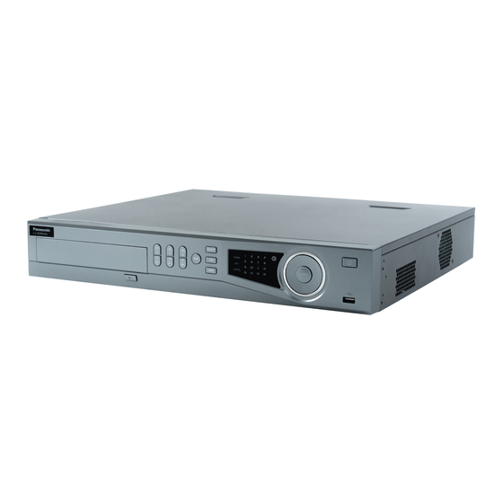
- Page 1 Network Disk Recorder User’s Manual K-NL404K/G Model No. K-NL408K/G K-NL416K/G Version 1.0.1...
-
Page 2: Table Of Contents
Table of Contents 1 Features and Specifications ..........1 Overview ............................1 Features ............................1 Specifications ..........................3 2 Front Panel and Rear Panel ..........5 Front Panel ............................ 5 Rear Panel ............................ 7 2.3 Alarm Connection(K-NL416K/G only) ..................10 2.3.1 Alarm Port ........................ - Page 3 4.2.1 Device Initialization ..................... 20 4.2.2 Reset Password ......................24 Navigation Bar ..........................26 4.3.1 Main Menu ........................26 4.3.2 Output Screen ......................26 4.3.3 Tour ..........................27 4.3.4 PTZ ..........................27 4.3.5 IMAGE ........................27 4.3.6 SEARCH ........................27 4.3.7 Alarm Status .......................
- Page 4 4.10 Alarm ............................82 4.10.1 Detect Alarm ....................... 82 4.10.2 Audio Detect ....................... 88 4.10.3 Alarm output ....................... 89 4.10.4 Alarm Setup ........................ 90 4.10.5 Abnormality ......................... 97 4.11 Network ............................99 4.11.1 TCP/IP ........................99 4.11.2 Network Test ......................113 4.12 HDD Setup ..........................
- Page 5 WAN Login ..........................159 Setup ............................161 5.8.1 REMOTE ........................161 5.8.2 Network ........................173 5.8.3 Event ......................... 184 5.8.4 Storage ........................201 5.8.5 SYSTEM ........................205 Information ..........................219 5.9.1 Version ........................219 5.9.2 Log ..........................219 5.9.3 Online User ....................... 220 5.9.4 HDD ..........................
- Page 6 Important Safeguards and Warnings 1.Electrical safety All installation and operation here should conform to your local electrical safety codes. The product must be grounded to reduce the risk of electric shock. We assume no liability or responsibility for all the fires or electric shock caused by improper handling or installation.
-
Page 7: Features And Specifications
1 Features and Specifications Overview This series NVR is a high performance network video recorder. This series product support local preview, multiple-window display, recorded file local storage, remote control and mouse shortcut menu operation, and remote management and control function. This series product supports centre storage, front-end storage and client-end storage. - Page 8 • Through network, sending audio/video data compressed by IPC or NVS to client-ends, then the data will be decompressed and display. • Support max 128 connections at the same time. Network • Transmit audio/video data by HTTP, TCP, UDP, MULTICAST, Monitor RTP/RTCP and etc.
-
Page 9: Specifications
Specifications Parameter Specifications K-NL404K/G K-NL408K/G K-NL416K/G System Resources 4/8-channel series product support 4/8-channel supports 16-channel connection respectively. supports FHD connections. 80Mbps. main stream bandwidth supports 200Mbps. Operation System Embedded Linux real-time operation system Operation Interface WEB/Local GUI Video Compression H.265/H.264/MJPEG... - Page 10 Desk installation Note EMS & Mobile-EMS do not support i-PRO series NVR Panasonic Security Viewer is not supported Bit rate: Suggested to set bit rate for E-Series camera to 2 Mbps or less Suggested to synchronize to external NTP server ...
-
Page 11: Front Panel And Rear Panel
Front Panel and Rear Panel Front Panel The front panel is shown as below. See Figure 2-1. K-NL404K/G, K-NL408K/G K-NL416K/G Figure 2-1 Please refer to the following sheet for front panel button information. Name Icon Function Power button, press this button for three seconds to boot up Power button or shut down NVR. - Page 12 In playback mode, playback the previous video Play previous/0 | In text mode, input number 0. In normal playback or pause mode, click this button to reverse playback Reverse/Pause/6 || In reverse playback, click this button to pause playback. In text mode, input number 6 (English character M/N/O) In playback mode, playback the next video Play Next/9 In menu setup, go to down ward of the dropdown list.
-
Page 13: Rear Panel
Status indicator STATUS The light is on if device operates properly. light Rear Panel The rear panel is shown as below. See Figure 2-2. K-NL404K/G K-NL408K/G K-NL416K/G Figure 2-2 Please refer to the following sheet for detailed information. Name Function Power Power ON/OFF button. - Page 14 Name Function Power input Input AC 100~240V. socket MIC IN Audio input port Bidirectional talk input port. It is to receive the analog audio signal output from the devices such as mike phone, pickup. Audio output port. It is to output the analog audio signal MIC OUT Audio output port to the devices such as the sound box.
- Page 15 Name Function Controller 12V power output. It is to control the on-off alarm relay output. It can be used to control the device CTRL 12V alarm output. At the same time, it can also be used as the power input source of some devices such as the alarm detector.
-
Page 16: Alarm Connection(K-Nl416K/G Only)
2.3 Alarm Connection(K-NL416K/G only) 2.3.1 Alarm Port The alarm port is shown as below. See Figure 2-3. Figure 2-3 Icon Function 1~16 ALARM1~ALARM16. The alarm becomes activated in the low level. NO1 C1,NO2 C2, NO3 C3 Three NO activation output groups. (On-off button). CTRL 12V Control power output. -
Page 17: Alarm Input And Output Port
When there is peripheral power supplying for the alarm device, please make sure it is earthed with the NVR. 2.3.3 Alarm input and output port There is peripheral power supplying for the external alarm device. In case overload may result in NVR damage, please refer to the following relay specifications for ... -
Page 18: Bidirectional Talk
Bidirectional talk 2.4.1 Device-end to PC-end Device Connection Please connect the speaker or the pickup to the first audio input port in the device rear panel. Then connect the earphone or the sound box to the audio output port in the PC. Login the Web and then enable the corresponding channel real-time monitor. -
Page 19: Pc-End To The Device-End
Listening Operation At the device end, speak via the speaker or the pickup, and then you can get the audio from the earphone or sound box at the pc-end. See Figure 2-5. Figure 2-5 2.4.2 PC-end to the device-end Device Connection Connect the speaker or the pickup to the audio output port in the PC and then connect the earphone or the sound box to the first audio input port in the device rear panel. -
Page 20: Mouse Operation
Mouse Operation Please refer to the following sheet for mouse operation instruction. Left click When you have selected one menu item, left click mouse to view menu content. mouse Modify checkbox or motion detection status. Click combo box to pop up dropdown list In input box, you can select input methods. -
Page 21: Remote Controller Operation
2.6 Remote Controller Operation Figure 2-7 Number Name Function Power button Click it to boot up or shut down the device. Address Click it to input device number, so that you can control it. Forward Various forward speeds and normal speed playback. Slow play Multiple slow play speeds or normal playback. - Page 22 Enter /menu key go to OK. Multiple-window Switch between multiple-window and one-window. switch In 1-ch monitor mode: pop up assistant function:PTZ control and Video color. Switch the PTZ control menu in PTZ control interface. In motion detection interface, working with direction keys to complete setup.
-
Page 23: Device Installation
Device Installation Note: All the installation and operations here should conform to your local electric safety rules. Check Unpacked NVR When you receive the NVR from the forwarding agent, please check whether there is any visible damage. The protective materials used for the package of the NVR can protect most accidental clashes during transportation. - Page 24 4. Turn the device upside down 6. Connect the HDD cable and Fix the HDD firmly. and then turn the screws in power cable. firmly. Note: Be careful so that the cables are not in contact with the edge of the HDD 7.
-
Page 25: Connection Sample
Connection Sample Please refer to Figure 3-1 for connection sample. Figure 3-1... -
Page 26: Local Basic Operation
Local Basic Operation Boot up and Shutdown 4.1.1 Boot up Before the boot up, please make sure: The rated input voltage matches the device. Please make sure the power wire connection is OK. Then click the power on-off button. Always use the stable current, if necessary UPS is a best alternative measure. - Page 27 Figure 4-1 Set login password of admin. Step 2 User name: The default user name is admin. Password/confirm password: The password ranges from 8 to 32 digitals. It can contain letters, numbers and special characters (excluding “'”,“"”,“;”,“:”) . The password shall contain at least three categories.
- Page 28 Step 3 Click Next, device goes to the following interface. See Figure 4-2. Figure 4-2 Step 4 Set unlock pattern. After set unlock pattern, device goes to password protection interface. See Figure 4-3. Note Device adopts unlock pattern to login by default if you have set pattern here. If there is no ...
- Page 29 Figure 4-3 Step 5 Set security questions. Note After setting the security questions here, you can answer the security questions to reset admin password. Refer to user’s manual for detailed information. Cancel the security questions box and then click Next button to skip this step. ...
-
Page 30: Reset Password
4.2.2 Reset Password If you forgot admin password, you can reset the password by answering the security questions (local menu only). Please follow the steps listed below. Step 1 Go to the device login interface. See Figure 4-4 or Figure 4-5. . If you have set unlock pattern, device displays unlock pattern login interface. - Page 31 Figure 4-5 Step 2 Click Reset login password by security questions. Security questions Device displays security question interface. See Figure 4-6. Please input the correct answers here. Figure 4-6 Step 3 Click Next button. Device displays reset password interface. See Figure 4-7.
-
Page 32: Navigation Bar
Figure 4-7 Step 4 Input new password and then confirm. WARNING STRONG PASSWORD RECOMMENDED-For your device own safety, please create a strong password of your own choosing. The password shall be at least 8-digit containing at least three types of the following categories: letters, numbers and symbols. We also recommend you change your password periodically especially in the high security system. -
Page 33: Tour
4.3.3 Tour Click button to enable tour, the icon becomes , you can see the tour is in process. 4.3.4 Click , system goes to the PTZ control interface. Please refer to chapter 4.6.2. 4.3.5 IMAGE Click button , system goes to the color interface. Please refer to chapter 4.4.3. Please make sure system is in one-channel mode. -
Page 34: Camera Registration
Figure 4-12 4.3.9 Camera Registration Click , system goes to the remote device interface. Please refer to chapter 4.4 4.3.10 Network Click , system goes to the network interface. It is to set network IP address, default gateway and etc. Please refer to chapter 4.11. -
Page 35: Remote Device
The default setup is TCP. See Figure 4-14. Important Please note the manual add function is for Private, Panasonic, Sony, Dynacolor, Samsung, AXIS, Arecont, ONVIF and Custom. When the type is the custom, you can just input URL address, user name and password connect to the network camera without considering network camera manufacturer. -
Page 36: Short-Cut Menu
Figure 4-14 4.4.2 Short-Cut Menu In the preview interface, for the channel of no IPC connection, you can click the icon “+” in the centre of the interface to quickly go to the Remote Device interface. See Figure 4-15. Figure 4-15... -
Page 37: Image
4.4.3 IMAGE From Main Menu->SETTING->REMOTE->IMAGE, you can see the camera interface is shown as below. See Figure 4-16. Channel: Select a channel from the dropdown list. Configuration: Here you can set up 4 modes of configurations for Day/Night switch: ... -
Page 38: Encode
OFF: It is to disable the BLC function. Please note this function is disabled by default. Scene Mode: It is to set the white balance mode. It has effect on the general hue of the video. This function is on by default. You can select the different scene mode such as auto, sunny, cloudy, home, office, night, disable and etc to adjust the video to the best quality. -
Page 39: Cam Name
4.4.5 CAM NAME From Main Menu->SETTING->REMOTE->CAM NAME, you can see an interface shown as in Figure 4-17. It is to modify channel name. It max supports 31-character. Please note you can only modify the channel name of the connected network camera. Figure 4-17 4.4.6 Upgrade... -
Page 40: Remote Device Info
Figure 4-18 4.4.7 Remote Device Info 4.4.7.1 Device Status Here you can view the IPC status of the corresponding channel such as motion detect, video loss, tampering, alarm and etc. See Figure 4-19. IPC status: : Front-end does not support. : Front-end supports. - Page 41 Figure 4-19 4.4.7.2 Firmware It is to view channel, IP address, manufacturer, type, system version, SN, video input, audio input, external alarm and etc. See Figure 4-20.
-
Page 42: Upnp
Figure 4-20 4.4.8 UPNP Important Do not connect the switch to the PoE port, otherwise the connection may fail! Please connect the IPC to the PoE port of the device rear panel as an example (Figure 4-21), system can auto connect to the network camera. Please note the following figure is for reference only. Figure 4-21 4.4.9 Built-in Switch Setup... -
Page 43: Preview
Figure 4-22 Preview After device booted up, the system is in multiple-channel display mode. See Figure 4-23.Please note the displayed window amount may vary. The following figure is for reference only. Please refer to chapter 1.3 Specifications for the window-amount your product supported. Figure 4-23... -
Page 44: Preview
4.5.1 Preview If you want to change system date and time, you can refer to general settings (Main Menu->SETTING->SYSTEM->GENERAL). If you want to modify the channel name, please refer to the display settings (Main Menu->SETTING->REMOTE->CAM NAME) Please refer to the following sheet for detailed information. Recording status Video loss Motion detection... -
Page 45: Right Click Menu
Figure 4-25 Put the middle button at the centre of the zone you want to zoom in, and move the mouse, you can view an interface shown as in Figure 4-26. Figure 4-26 Right click mouse to cancel zoom and go back to the original interface. Realtime Backup It is to backup the video of current channel to the USB device. -
Page 46: Sequence
PTZ: Click it to go to PTZ interface. IMAGE: Set video corresponding information. Search: Click it to go to Playback interface to search and playback a record file. Manual: Enable/disable record channel. Alarm output: It is to set alarm output mode. Generate alarm output signal manually. ... - Page 47 Figure 4-28 Step 2 On the edit view interface, drag the channel to the desired window, or drag on the preview window to switch the position. Check the channel number at the right bottom corner to view the current channel sequence. See Figure 4-29.
-
Page 48: Preview Display Effect Setup
Figure 4-29 Step 3 Click Apply to save current channel sequence. After you change the channel sequence, click Cancel button or right click mouse, device pops up the dialogue box. See Figure 4-30. Click OK to save current settings. Click Cancel to exit without saving the settings. - Page 49 Figure 4-31 Now you can set corresponding information. Resolution: There are four options: 1280×1024 (Default), 1280×720, 1920×1080, 1024×768. Please note the system needs to reboot to activate current setup. Transparency: Here is for you to adjust transparency. The value ranges from 0 to 100. ...
-
Page 50: Ptz
Figure 4-32 Tips On the navigation bar, click to enable/disable tour. Click Save button to save current setup. Note: Before you control the PTZ, please make sure the PTZ decoder and the NVR network connection is OK and the corresponding settings are right. 4.6.1 PTZ Settings Cable Connection... - Page 51 PTZ Type: There are two types: local/remote. Please select local mode if you are connect RS485 cable to connect to the Speed dome (PTZ). Please select remote mode if you are connecting to the network PTZ camera. Protocol: Select corresponding PTZ protocol(such as PELCOD) ...
-
Page 52: Ptz Control
Figure 4-37 4.6.2 PTZ Control After completing all the setting please click Save button. Right click mouse (click “FN” Button in the front panel or click “FN” key in the remote control). The interface is shown as in Figure 4-38. Figure 4-38 The PTZ setup is shown as in See Figure 4-39. - Page 53 Speed is to control PTZ movement speed. The value ranges from 1 to 8.The speed 8 is faster than speed 1. You can use the remote control to click the small keyboard to set. You can click of the zoom, focus and iris to zoom in/out, definition and brightness. The PTZ rotation supports 8 directions.
- Page 54 Right click mouse or click the ESC button at the front panel to go back to the Figure 4-29. Icon Function Icon Function Preset Flip Tour Reset Pattern Aux Config Autoscan Aux on-off button AutoPan Enter menu 4.6.2.1 PTZ Function Setup Click , you can go to the following interface to set preset, tour, pattern, and scan.
- Page 55 Tour Setup In Figure 4-41, click tour tab. Input tour value and preset No. Click Add Preset button to add current preset to the tour. See Figure 4-42. Tips Repeat the above steps to add more presets to the tour. Click Del Preset button to remove it from the tour. Please note some protocols do not support delete preset function.
- Page 56 4.6.2.2 Call PTZ Function Call Preset In Figure 4-41, input preset value and then click to call a preset. Click again to stop call. Call Pattern In Figure 4-41, input pattern value and then click to call a pattern. Click again to stop call.
-
Page 57: Record And Snapshot
Record and Snapshot The record/snapshot priority is: ALARM->MOTION DETECT->SCHEDULE. 4.7.1 ENCODE 4.7.1.1 Encode Encode setting is to set IPC encode mode, resolution, bit stream type and etc. From Main menu->SETTING->REMOTE->ENCODE, you can see the following interface. See Figure 4-46. Channel: Select the channel you want. ... - Page 58 Figure 4-46 Figure 4-47 4.7.1.2 Snapshot Here you can set snapshot mode, picture size, quality and frequency. See Figure 4-48. Mode: There are two modes: timing and trigger. If you set timing mode, you need to set snapshot frequency. If you set trigger snapshot, you need to set snapshot activation operation. Image size: Here you can set snapshot picture size.
- Page 59 Figure 4-48 4.7.1.3 Overlay Click Overlay tab, you can see an interface is shown in Figure 4-49. Cover area: Here is for you to cover area section. You can drag you mouse to set proper section size. In one channel video, system max supports 4 zones in one channel. You can set with Fn button or direction buttons.
-
Page 60: Schedule
Figure 4-49 4.7.2 Schedule The record type priority is: Alarm>Motion detect>Regular. 4.7.2.1 Basic It is to manage HDD storage space. See Figure 4-50. Parameter Function Overwrite: If the current HDD is full while there is no idle HDD, then HDD full ... - Page 61 Figure 4-50 4.7.2.2 Schedule Record Set record time, record plan and etc. Please note system is in 24-hour record by default after its first boot up. In the main menu, from Main menu->SETTING->STORAGE->SCHEDULE, you can go to schedule menu. See Figure 4-51. There are total six periods.
- Page 62 Figure 4-51 Channel: Please select the channel number first. You can select “all” if you want to set for the whole channels. : Sync connection icon. Select icon of several dates, all checked items can be edited or together. Now the icon is shown as : Click it to delete a record type from one period.
- Page 63 Period setup: Click button after one date or a holiday, you can see an interface shown as in Figure 4-55. There are four record types: Regular, Motion detection (MD), Alarm, MD & alarm. Please following the steps listed below to draw the period manually. Select a channel you want to set.
- Page 64 Figure 4-55 Quick Setup Copy function allows you to copy one channel setup to another. After setting in channel 1, click Copy button, you can go to interface Figure 4-56. You can see current channel name is gray such as channel 1. Now you can select the channel you wan to paste such as channel 5/6/7.
- Page 65 Figure 4-57 From Main menu->SETTING->REMOTE->ENCODE->Snapshot, you can go to snapshot interface. See Figure 4-58. Select the snapshot channel from the dropdown list and then select snapshot mode as Timing (Schedule) from the dropdown list and then set picture size, quality and snapshot frequency.
- Page 66 Figure 4-58 In the main menu, from Main menu->SETTING->STORAGE->SCHEDULE, you can go to schedule menu. See Figure 4-59. Here you can set snapshot period. There are total six periods in one day. Please refer to chapter 4.7.2.2 for detailed setup information. The setup steps are general the same.
-
Page 67: Motion Detect Record/Snapshot
Figure 4-59 Note Please note the trigger snapshot has the higher priority than regular snapshot. If you have enabled these two types at the same time, system can activate the trigger snapshot when an alarm occurs, and otherwise system just operates the regular snapshot. Only the trigger snapshot supports this function. - Page 68 Figure 4-60 Select motion detect from the event type dropdown list. Select a channel from the dropdown list and then check the enable box to enable motion detect function. Click Region Setup button to set motion detect zone. There are 396(PAL)/330(NTSC) small zones.
- Page 69 Figure 4-61 Figure 4-62...
-
Page 70: Alarm Record/Snapshot
4.7.3.2 Motion Detect Snapshot From Main menu->SETTING->REMOTE->ENCODE->Snapshot, you can go to snapshot interface. See Figure 4-63. In Figure 4-63, select trigger snapshot from the dropdown list and then set picture size, quality and snapshot frequency. Click Save button to save current setup. From Main menu->SETTING->EVENT->DETECT, here you can select motion detect type, motion detect channel and then check the enable box. - Page 71 Network input alarm: It is the alarm signal from the network. IPC external alarm: It is the on-off alarm signal from the front-end device and can activate the local NVR. IPC offline alarm: Once you select this item, system can generate an alarm when the front-end ...
-
Page 72: Manual Record/Snapshot
4.7.5 Manual Record/Snapshot You need to have proper rights to implement the following operations. Please make sure the HDD has been properly installed. 4.7.5.1 Manual Record Right click mouse select manual record main menu, from SETTING->STORAGE->RECORD. Manual record menu is shown as in Figure 4-65. Tips You can click REC button on the front panel (if possible) to go to the Manual Record interface. -
Page 73: Holiday Record/Snapshot
menu->SETTING->REMOTE->ENCODE->Snapshot, you can set snapshot times. You can go to chapter 4.8 to view snapshot picture. 4.7.6 Holiday Record/Snapshot It is for you to set holiday record or snapshot plan. Please note the holiday record/snapshot setup has the higher priority than the ordinary date record/snapshot setup. 4.7.6.1 Holiday Record From Main menu->SETTING->SYSTEM->GENERAL, you can go to the following interface. - Page 74 Figure 4-67 Click Add button to complete holiday setup. Now you can enable holiday setup and then click Apply button. From Main menu->SETTING->STORAGE->SCHEDULE, you can go to schedule interface. See Figure 4-68. Now you can set period and record type of holiday time. Please refer to chapter 4.7.2.1 for detailed setup information.
-
Page 75: Other Record/Snapshot
Figure 4-68 Click OK button to set holiday record setup. 4.7.6.2 Holiday Snapshot Set Holiday date first. Please refer to step a) to step c) of chapter 4.7.6.1. From Main menu->SETTING->STORAGE->SCHEDULE, you can go to schedule interface. See Figure 4-68. Click Holiday item to set snapshot period. Set holiday snapshot type (Trigger/Regular). -
Page 76: Playback And Search
Playback and Search 4.8.1 Real-time Playback Please refer to chapter 4.5.2 for real-time playback information. 4.8.2 Playback Interface From Main menu->Playback, or on the preview interface right click mouse and then select playback item, you can go to the following interface. See Figure 4-69. Figure 4-69 Please refer to the following sheet for more information. - Page 77 Click it to go to mark file list interface. You can view all mark information of Mark file current channel by time. Please refer to chapter 4.8.2.3 for detailed information. list button Please note only the product of this icon supports mark function. Double click it, you can view the picture/record file list of current day.
- Page 78 In normal play mode, left click the button, the file begins backward play. Click it again to pause current play. In backward play mode, click ►/ to restore normal play. In playback mode, click it to play the next or the previous section. You can click continuously when you are watching the files from the same channel.
- Page 79 The time bar is beginning with 0 o'clock when you are setting the configuration. The time bar zooms in the period of the current playback time when you are playing the file. Select the file(s) you want to backup from the file list. You can check from ...
- Page 80 Other channel synchroni zation When playing the file, click the number button, system can switch to the same switch to period of the corresponding channel to play. play when playback When the system is in full-screen playback mode, left click the mouse in the Digital screen.
- Page 81 Click the Smart Search , you can go to the smart search playback. Click it again, system stops smart search playback. Important System does not support motion detect zone setup during the full-screen mode. During the multiple-channel playback, system stops playback of rest channels if you ...
- Page 82 4.8.2.3 Mark Playback Please make sure your purchased device support this function. You can use this function only if you can see the mark playback icon on the Playback interface (Figure 4-69). When you are playback record, you can mark the record when there is important information. After playback, you can use time or the mark key words to search corresponding record and then play.
-
Page 83: Picture Playback
Figure 4-73 Modify Double click one mark information item, you can see system pops up a dialogue box for you to change mark information. You can only change mark name here. Delete Here you can check the mark information item you want to delete and then click Delete button, you can remove one mark item. -
Page 84: Backup
Backup 4.9.1 File Backup In this interface, you can backup record file to the USB device. a) Connect USB burner, USB device or portable HDD and etc to the device. b) From Main menu->BACKUP, you can go to the Backup interface. See Figure 4-74 Figure 4-74 c) Select backup device and then set channel, file start time and end time. -
Page 85: Import/Export
Figure 4-75 h) Click Start button, system begins burning. At the same time, the Start button becomes stop button. You can view the remaining time and process bar at the left bottom. Note During backup process, you can click ESC to exit current interface for other operation (For ... - Page 86 Figure 4-76 Export: Please connect the peripheral device first and then go to the following interface. Click Export button, you can see there is a corresponding “Config_Time” folder. Double click the folder, you can view some backup files. Import: Here you can import the configuration files from the peripheral device to current device. You ...
-
Page 87: Backup Log
4.9.3 Backup Log a) From Main menu->INFO->LOG, the interface is shown as below. See Figure 4-77. Figure 4-77 b) Select log type and then set start time/end time, click Search button, you can see log time and event information. Click to view detailed log information. -
Page 88: Alarm
Figure 4-77-1 4.10 Alarm 4.10.1 Detect Alarm In the main menu, from Setting to Detect, you can see motion detect interface. See Figure 4-78.There are three detection types: motion detection, video loss, tampering. 4.10.1.1 Motion Detect After analysis video, system can generate a motion detect alarm when the detected moving signal reached the sensitivity you set here. - Page 89 Period: Click setup button, you can see an interface is shown as in Figure 4-82. Here you can set motion detect period. System only enables motion detect operation in the specified periods. It is not for video loss or the tampering. There are two ways for you to set periods. Please note system only supports 6 periods in one day.
- Page 90 Figure 4-78 Figure 4-79...
- Page 91 Figure 4-80 Figure 4-81...
- Page 92 Figure 4-82 Motion detect here only has relationship with the sensitivity and region setup. It has no relationship with other setups. 4.10.1.2 Video Loss After connected the system to the remote device, system can generate an alarm once the remote device has lost the video.
- Page 93 Figure 4-83 4.10.1.3 Tampering When someone viciously masks the lens, or the output video is in one-color due to the environments light change, the system can alert you to guarantee video continuity. Tampering interface is shown as in Figure 4-84. You can enable “Alarm output “or “Show message” function when tampering alarm occurs.
-
Page 94: Audio Detect
Figure 4-84 4.10.2 Audio Detect System can generate an alarm once it detect the audio is not clear, the tone color has changed or the is abnormal or audio volume changes. From main menu->Setting->Event->Audio detect, you can see an interface shown as in Figure 4-84-1. Input abnormal: Check the box here, system can generate an alarm once the audio input is ... -
Page 95: Alarm Output
Figure 4-84-1 4.10.3 Alarm output From Main menu->SETTING->EVENT->ALARM OUTPUT, you can see an interface shown as in Figure 4-85. Here is for you to set proper alarm output (Auto/Manual/Stop). Click OK button of the alarm reset, you can clear all alarm output status. -
Page 96: Alarm Setup
Figure 4-85 Please highlight icon to select the corresponding alarm output. After all the setups please click OK button, system goes back to the previous menu. 4.10.4 Alarm Setup In the main menu, from SETTING->EVENT->ALARM, you can see alarm setup interface. See Figure 4-86. - Page 97 Channel: Here is for you to select channel number. Enable: Please you need to highlight this button to enable current function. Type: normal open or normal close. Period: Click Setup button, you can see an interface is shown as in Figure 4-91. There are two ways ...
- Page 98 Tour: Here you can enable tour function when an alarm occurs. System supports 1/8-window tour. Please go to chapter4.5.4. Display for tour interval setup. Please note the tour setup here has higher priority than the tour setup you set in the Display interface. Once there two tours are both enabled, system can enable the alarm tour as you set here when an alarm occurred.
- Page 99 Figure 4-87 Figure 4-88...
- Page 100 Figure 4-89 Figure 4-90...
- Page 101 Figure 4-91 Figure 4-92...
- Page 102 Please highlight icon to select the corresponding function. After setting all the setups please click save button, system goes back to the previous menu.
-
Page 103: Abnormality
4.10.5 Abnormality There are three types: HDD/Network/User. HDD: HDD error, no HDD, no space. See Figure 4-93 and Figure 4-94. Network: Disconnection, IP conflict, MAC conflict. See Figure 4-95. User: Illegal login. Figure 4-96. Alarm Out: Please select alarm activation output port (multiple choices). ... - Page 104 Figure 4-94 Figure 4-95...
-
Page 105: Network
Figure 4-96 4.11 Network 4.11.1 TCP/IP The single network adapter interface is shown as in Figure 4-98 . IP Version: There are two options: IPv4 and IPv6. Right now, system supports these two IP address format and you can access via them. MAC Address: The host in the LAN can get a unique MAC address. - Page 106 button to confirm current reboot, or you can click Cancel button to terminate current modification. Before the modification, you can check the MTU of the gateway; the MTU of the NVR shall be the same as or is lower than the MTU of the gateway. In this way, you can reduce packets and enhance network transmission efficiency.
- Page 107 RTSP port: Default value is 554. Important: System needs to reboot after you changed and saved any setup of the above four ports. Please make sure the port values here do not conflict. Figure 4-99 4.11.1.2 PPPoE PPPoE interface is shown as in Figure 4-100. Input “PPPoE name”...
- Page 108 Figure 4-100 4.11.1.3 DDNS DDNS setup interface is shown as in Figure 4-101. You need a PC of fixed IP in the internet and there is the DDNS software running in this PC. In other words, this PC is a DNS (domain name server). In network DDNS, please select DDNS type and highlight enable item.
- Page 109 Figure 4-101 Please note DDNS type includes: CN99 DDNS, NO-IP DDNS and Dyndns DDNS. All the DDNS can be valid at the same time, you can select as your requirement. 4.11.1.4 UPnP The UPNP protocol is to establish a mapping relationship between the LAN and the WAN. Please input the router IP address in the LAN in Figure 4-98.
- Page 110 Double click one item; you can change the corresponding mapping information. See Figure 4-103. Important: When you are setting the router external port, please use port 1024~5000. Do not use well-known port 1~255 and the system port 256~1023 to avoid conflict. For the TCP and UDP, please make sure the internal port and external port are the same to guarantee the proper data transmission.
- Page 111 4.11.1.5 IP Filter IP filter interface is shown as in Figure 4-104. You can add IP in the following list. The list supports max 64 IP addresses. System supports valid address of IPv4 and IPv6. Please note system needs to check the validity of all IPv6 addresses and implement optimization.
- Page 112 Figure 4-104 Figure 4-105...
- Page 113 4.11.1.6 Email The email interface is shown as below. See Figure 4-106. SMTP server: Please input your email SMTP server IP here. Anonymous: Send anonymous email Port: Please input corresponding port value here. User name: Please input the user name to login the sender email box. ...
- Page 114 Figure 4-106 4.11.1.7 FTP You need to download or buy FTP service tool (such as Serv-U FTP SERVER) to establish FTP service. Please install Serv-U FTP SERVER first. From “start” -> “program” -> Serv-U FTP Server -> Serv-U Administrator. Now you can set user password and FTP folder. Please note you need to grant write right to FTP upload user.
- Page 115 auto ignore the left section. When interval value is 0, system uploads all corresponding files. After completed channel and weekday setup, you can set two periods for one each channel. Click the Test button, you can see the corresponding dialogue box to see the FTP connection is OK or not.
- Page 116 Figure 4-110 Please enable the SNMP function. Use the corresponding software tool (MIB Builder and MG-SOFT MIB Browser. You still need two MIB file: BASE-SNMP-MIB, NVR-SNMP-MIB) to connect to the device. You can get the device corresponding configuration information after successfully connection. Please follow the steps listed below to configure.
- Page 117 4.11.1.9 Multicast Multicast setup interface is shown as in Figure 4-111. Figure 4-111 Here you can set a multiple cast group. Please refer to the following sheet for detailed information. IP multicast group address -224.0.0.0-239.255.255.255 -“D” address space The higher four-bit of the first byte=”1110” ...
- Page 118 Used for multiple cast broadcast in limited space. Except the above mentioned addresses of special meaning, you can use other addresses. For example: Multiple cast IP: 235.8.8.36 Multiple cast PORT: 3666. After you logged in the Web, the Web can automatically get multiple cast address and add it to the multiple cast groups.
-
Page 119: Network Test
Figure 4-113 4.11.2 Network Test In this interface, you can see network test and network load information. 4.11.2.1 Network Test From main menu->INFO->NETWORK->TEST, the network test interface is shown as in Figure 4-114. Destination IP: Please input valid IPV4 address and domain name. ... - Page 120 Figure 4-114 4.11.2.2 Network Load From main menu->INFO->NETWORK->LOAD, network load is shown as in Figure 4-115. Here you can view the follow statistics of the device network adapter. Here you can view information of all connected network adapters. The connection status is shown as offline if connection is disconnected.
- Page 121 Figure 4-115...
-
Page 122: Hdd Setup
4.12 HDD Setup Here you can view HDD information such as type, status, total capacity, record time and etc. The operation includes format, resume from error, change HDD property (Read write, Read-only). Here you can also set alarm and HDD storage position. 4.12.1 BASIC HDD Full: Here is for you to select working mode when hard disk is full. -
Page 123: Hdd Information
Figure 4-116 b) Select a HDD and then select format from the dropdown list. Click Format button. c) Click OK button to complete the setup. You can see system needs to restart to activate current setup. 4.12.3 HDD Information Here is to list hard disk type, total space, free space, and status. See Figure 4-117. ○... - Page 124 Figure 4-117 In Figure 4-117, click one HDD item, the S.M.A.R.T interface is shown as in Figure 4-118.
- Page 125 Figure 4-118 Parameter Function SATA 1 here means there is 1 HDD. For different series product, the max HDD amount may vary, When HDD is working properly, system is shown as O. . “_” means there is no HDD. You can view the HDD amount the device connected to; ﹡...
-
Page 126: Advanced
View Click it to view HDD record information (file start time and end time). recording time View Click it to view HDD property, status and etc, type capability 4.12.4 Advanced It is to set HDD group, and HDD group setup for main stream, extra stream and snapshot operation Important HDD group and quota mode cannot be valid at the same time. - Page 127 Figure 4-120 Figure 4-121...
-
Page 128: Hdd Detect
Figure 4-122 4.12.5 HDD DETECT From main menu->Setting->Storage->HDD Detect->Manual Detect, the interface is shown as below. Please select detect type and HDD. Click start detect to begin. You can view the corresponding detect information. After the detect operation, you can go to the detect report to view corresponding information. From main menu->Setting->Storage->HDD Detect->Detect Report, the interface is shown as below. -
Page 129: Basic Setups
4.13 Basic Setups Set NVR basic setup, device setup and other setups. 4.13.1 Device Setup From Main menu->SETTING->SYSTEM->GENERAL, you can go to the general interface. See Figure 4-123. Device Name: Please input a corresponding device name here. Device No: When you are using one remote control (not included in the accessory bag) to control ... -
Page 130: Data And Time
Figure 4-123 4.13.2 Data and Time From Main menu->SETTING->SYSTEM->GENERAL, you can go to the general interface. See Figure 4-124. System time: Here is for you to set system time Date Format: There are three types: YYYY-MM-DD: MM-DD-YYYY or DD-MM-YYYY. ... -
Page 131: Holiday
Figure 4-124 4.13.3 Holiday Holiday setup interface is shown as in Figure 4-125. Click Add Holidays button, you can input new holiday information. See Figure 4-126. Here you can set holiday name, repeat mode and start/end time. - Page 132 Figure 4-125 Figure 4-126...
-
Page 133: Device Maintenance And Manager
4.14 Device Maintenance and Manager 4.14.1 System Info 4.14.1.1 Version From main menu->INFO->SYSTEM->VERSION, you can go to version interface. Here is for you to view some version information. See Figure 4-127. Please note the following figure for reference only. Channel ... - Page 134 Figure 4-128 4.14.1.3 Online User Here is for you manage online users connected to your NVR. See Figure 4-129. You can click button to disconnect or block one user if you have proper system right. System detects there is any newly added or deleted user in each five seconds and refresh the list automatically.
- Page 135 Figure 4-129 4.14.1.4 Remote Device Information From main menu->INFO->EVENT, here you can view the channel status of the remote device, connection log and etc. See Figure 4-130.
- Page 136 Figure 4-130 4.14.1.5 Remote 4.14.1.5.1 Device Status Here you can view the IPC status of the corresponding channel such as motion detect, video loss, tampering, alarm and etc. See Figure 4-131. IPC Status: : Front-end does not support. : Front-end supports. : There is alarm ...
- Page 137 Figure 4-131 4.14.1.5.2 Firmware It is to view Channel, IP Address, Manufacturer, Type, System Version, SN, Video Input, Audio Input, External Alarm and etc. See Figure 4-132.
-
Page 138: Log
Figure 4-132 4.14.2 Log From Main menu->INFO->LOG, you can go to the following interface. See Figure 4-133. Start Time/End time: Pleased select start time and end time, then click search button. You can view the log files in a list. System max displays 100 logs in one page. It can max save 1024 log files. Please use page up/down button on the interface or the front panel to view more. - Page 139 Figure 4-133 Figure 4-134...
-
Page 140: Account
4.14.3 Account Here is for you to implement account management. See Figure 4-135 and Figure 4-136. Here you can: Add User Modify User Add Group Modify Group Modify Password. For account management please note: For the user account name and the user group, the string max length is 6-byte. The backspace in ... - Page 141 Figure 4-136...
- Page 142 4.14.3.1 Add/Modify Group Click add group button, the interface is shown as below. See Figure 4-137. Here you can input group name and then input some memo information if necessary. There are many rights for System, Playback, Monitor and etc. The modify group interface is similar to the Figure 4-137.
- Page 144 Figure 4-138 4.14.3.3 Security Question This function is for admin user only. Here you can change security questions. After you successfully answered security questions, you can reset admin account password. From main menu->Setting->System->Account->Security question, the interface is shown as below. See Figure 4-139.
- Page 145 Figure 4-139 4.14.3.4 OVVIF User When the camera from the third party is connected with the DVR via the ONVIF user, please use the verified ONVIF account to connect to the DVR. Here you can add/delete/modify user Note The default ONVIF user is admin. It is created after you initialize the DVR. Step 1 From main menu->Setting->System->Account->ONVIF User.
- Page 146 Figure 4-140 Step 2 Click Add user button. Enter Add user interface. See Figure 2-141.
-
Page 147: Upgrade
Figure 4-141 Step 3 Set user name, password and then select group from the dropdown list. Step 4 Click Save to complete setup. Note Click to change user information, click to delete current user. 4.14.4 UPGRADE From Main menu->SETTING->SYSTEM->UPGRADE, you can go to the following interface. See Figure 4-142. -
Page 148: Default
Figure 4-142 4.14.5 DEFAULT You can restore factory default setup to fix some problems when the device is running slowly, Configuration error occurred. From Main menu->SETTING->SYSTEM->DEFAULT, you can go to the default interface. See Figure 4-143. Click default icon, system pops up a dialogue box. You can highlight to restore factory default setup. -
Page 149: Rs232
Figure 4-143 4.14.6 RS232 From Main menu->SETTING->SYSTEM->RS232, RS232 interface is shown as below. There are five items. See Figure 4-144. Function: There are various devices for you to select. Console is for you to use the COM or mini-end software to upgrade or debug the program. -
Page 150: Voice Prompt
Figure 4-144 4.14.7 Voice Prompt The audio function is to manage audio files and set schedule play function. It is to realize audio broadcast activation function. 4.14.7.1 File Manage Here you can add audio file, listen to the audio file, or rename/delete audio file. Here you can also set audio volume. - Page 151 Figure 4-144-1...
-
Page 152: Auto Maintain
4.14.7.2 Schedule It is to set schedule broadcast function. You can play the different audio files in the specified periods. See Figure 4-144-2. Figure 4-144-2 4.14.8 Auto Maintain Here you can set auto-reboot time and auto-delete old files setup. You can set to delete the files for the specified days. -
Page 153: Logout /Shutdown/Restart
Figure 4-145 4.14.9 Logout /Shutdown/Restart From Main menu->OPERATION->SHUTDOWN, you can see an interface shown as in Figure 4-146. Shutdown: System shuts down and turns off power. Logout: Log out menu. You need to input password when you login the next time. ... -
Page 154: Web Operation
5 Web Operation 5.1 General Introduction The device web provides channel monitor menu tree, search, alarm setup, system setup, PTZ control and monitor window and etc. 5.1.1 Preparation Before log in, please make sure: Network connection is right NVR and PC network setup is right. Please refer to network setup(main ... -
Page 155: Log In
If system finds the previous information and the channel is idle, system can map it to the previously used channel. Otherwise system goes to the next step. Thirdly, according to the <PoE port>---<Channel> map, system can know the previous mapping channel of current PoE port. System can select current channel if it is free. Otherwise, it goes to the next step: Fourthly, system goes to find the first idle channel it can get. - Page 156 Figure 5-2 After installation, the interface is shown as below. If it is your first time to use the device, please set a login password of admin (system default user). See Figure 5-3. For detailed information, please refer to section 4.2. HDMI GUI is different from Web operation.
- Page 158 Please input your username and password. Figure 5-3...
-
Page 159: Lan Mode
5.2 LAN Mode For the LAN mode, after you logged in, you can see the main window. See Figure 5-8. This main window can be divided into the following sections. Section 1: there are six function buttons: Preview, Setup (chapter 5.8), Info (Chapter 5.9), Playback ... - Page 160 Figure 5-7 Section 6: Multi Preview button. Please refer to chapter 5.6 for detailed information. Section 7: PTZ operation panel. Please refer to chapter 5.4 for detailed information. Section 8: Image setup and alarm setup. Please refer to chapter 0 for detailed information. ...
-
Page 161: Real-Time Monitor
5.3 Real-time Monitor In section 2, left click the channel name you want to view, you can see the corresponding video in current window. On the top left corner, you can view device IP(172.11.10.11), channel number(1), network monitor bit stream(2202Kbps) and stream type(M=main stream, S=sub stream). See Figure 5-9. Figure 5-9 On the top right corner, there are six unction buttons. - Page 162 Parameter Function Select Scan from the dropdown list. Scan Click Set button, you can set scan left and right limit. Use direction buttons to move the camera to you desired location and then click left limit button. Then move the camera again and then click right limit button to set a right limit.
- Page 163 3D Intelligent Positioning You can click this icon to display or hide the PTZ control platform. Figure 5-11...
-
Page 164: Image/Alarm-Out
5.5 Image/Alarm-out Select one monitor channel video and then click Image button in section 9, the interface is shown as Figure 5-12. 5.5.1 Image Here you can adjust its view of image. (Current channel border becomes green). Or you can click Reset button to restore system default setup. Figure 5-12 5.5.2 Alarm output Here you can enable or disable the alarm signal of the corresponding port. -
Page 165: Wan Login
Figure 5-14 5.7 WAN Login In WAN mode, after you logged in, the interface is shown as below. See Figure 5-15. Figure 5-15... - Page 166 Please refer to the following contents for LAN and WAN login difference. 1) In the WAN mode, system opens the main stream of the first channel to monitor by default. The open/close button on the left pane is null. 2) You can select different channels and different monitor modes at the bottom of the interface. See Figure 5-16.
-
Page 167: Setup
5.8 Setup 5.8.1 REMOTE 5.8.1.1 Remote Device Remote device interface is shown as below. See Figure 5-17. Figure 5-17 Please refer to the following sheet for log parameter information. Parameter Function Click Device search button, you can view the searched device Device Search information on the list. - Page 168 You can select a channel from the dropdown list (Here only shows disconnection channel.) Note: System supports manufactures such as Private, Panasonic, Sony, Dynacolor, Samsung, AXIS, Arecont, Dahua and Onvif standard protocol. If you do not input IP address here. System uses default IP ...
- Page 169 Please refer to the following sheet for parameter information. Parameter Function Manufacturer Please select from the dropdown list. Note Different series products may support different manufacturers, please refer to the actual product. IP address Input remote device IP address. Input RTSP port of the remote device. The default setup is 554. RTSP port Note Skip this item if the manufacture is private or customize.
- Page 170 Change IP On the searched devices list, check one or more device(s) at the same time. Click Modify IP button, you can see the following interface. See Figure 5-19. Please refer to the following sheet for log parameter information. Parameter Function DHCP Check the box here, system can auto allocate the IP...
- Page 171 Figure 5-19 Export IP You can export the list of the added devices to your local PC. Click Export button and then select the saved path. Click OK. You can see “Backup completed ” prompt. Note The export file extension name is .CSV. The file contains IP address, port, remote channel No. manufacturer, user name, password and etc.
- Page 172 Important You can edit the exported file. Please make sure the file format is the same. Otherwise you cannot import the file again! System does not support customized protocol import/export. The import/export function is for the devices of the same language. ...
- Page 173 5.8.1.3 IMAGE Here you can view device property information. The setups become valid immediately after you set. See Figure 5-21. Figure 5-21 Please refer to the following sheet for detailed information. Parameter Function Channel Please select a channel from the dropdown list. Config File It sets 3 patterns.
- Page 174 Contrast It is to adjust monitor window contrast. The value ranges from 0 to 100. The default value is 50. The larger the number is, the higher the contrast is. You can use this function when the whole video bright is OK but the contrast is not proper.
- Page 175 Color: Device outputs the color video. Auto: Device auto select to output the color or the B/W video according to the device feature (The general bright of the video or there is IR light or not.) B/W: The device outputs the black and white video. ...
- Page 176 5.8.1.4 ENCODE 5.8.1.4.1 Encode The encode interface is shown as below. See Figure 5-22. Figure 5-22 Please refer to the following sheet for detailed information. Parameter Function Channel Please select a channel from the dropdown list. Video Enable Check the box here to enable extra stream video. This item is enabled by default.
- Page 177 mode, the bit stream is near the specified value. In VBR mode, the video quality changes according to the bit stream value. But its max value is near the specified value. Reference bit rate: The reference bit rate depends on the resolution and frame rate you set.
- Page 178 5.8.1.4.3 Overlay The video overlay interface is shown as in Figure 5-24. Figure 5-24 Please refer to the following sheet for detailed information. Parameter Function Check Preview or Monitor first. Cover-Area Click Set button, you can privacy mask the specified video in the preview or monitor video.
-
Page 179: Network
Figure 5-25 5.8.1.5 Camera Name Here you can set camera name. See Figure 5-26. Figure 5-26 5.8.2 Network 5.8.2.1 TCP/IP The TCP/IP interface is shown as in Figure 5-27. Figure 5-27... - Page 180 Please refer to the following sheet for detailed information. Parameter Function Mode There are two modes: static mode and the DHCP mode. The IP/submask/gateway are null when you select the DHCP mode to auto search the IP. If you select the static mode, you need to set the IP/submask/gateway manually.
- Page 181 Figure 5-28 5.8.2.2 EZ REMOTE The EZ Remote interface is shown as in Figure 5-29. You can use Mobile EMS to scan the QR code to login. Figure 5-29...
- Page 182 5.8.2.3 Port The connection interface is shown as in Figure 5-30. Figure 5-30 Please refer to the following sheet for detailed information. Parameter Function Max Connection It is the max Web connection for the same device. The value ranges from 1 to 120. The default setup is 120. TCP Port The default value is 37777.
- Page 183 Figure 5-31 5.8.2.5 DDNS The DDNS interface is shown as in Figure 5-32. The DDNS is to set to connect the various servers so that you can access the system via the server. Please go to the corresponding service website to apply a domain name and then access the system via the domain.
- Page 184 Parameter Function Interval Device sends out alive signal to the server regularly. You can set interval value between the device and DDNS server here. 5.8.2.6 IP Filter(Security) The IP filter interface is shown as in Figure 5-33. After you enabled trusted sites function, only the IP listed below can access current NVR. If you enable blocked sites function, the following listed IP addresses cannot access current NVR.
- Page 185 Figure 5-34 Please refer to the following sheet for detailed information. Parameter Function Please check the box here to enable email function. Enable Input server address and then enable this function. SMTP Server Port Default value is 25. You can modify it if necessary. Anonymity For the server supports the anonymity function.
- Page 186 Parameter Function email according to the interval you specified here. This function is very useful when there are too many emails activated by the abnormity events, which may result in heavy load for the email server. Please check the box here to enable this function. Health mail enable This function allows the system to send out the test email to...
- Page 187 Here you can also add, modify or remove UPnP item. See Figure 5-36. In the Windows OS, From Start->Control Panel->Add or remove programs. Click the “Add/Remove Windows Components” and then select the “Network Services” from the Windows Components Wizard. Click the Details button and then check the “Internet Gateway Device Discovery and Control client”...
- Page 188 Please refer to the following sheet for detailed information. Parameter Function SNMP Port The listening port of the proxy program of the device. It is a UDP port not a TCP port. The value ranges from 1 to 65535. The default value is 161 It is a string.
- Page 189 5.8.2.11 Multicast The multicast interface is shown as in Figure 5-38. Multicast is a transmission mode of data packet. When there is multiple-host to receive the same data packet, multiple-cast is the best option to reduce the broad width and the CPU load. The source host can just send out one data to transit.
-
Page 190: Event
5.8.3 Event 5.8.3.1 VIDEO Detect 5.8.3.1.1 Motion Detect After analysis video, system can generate a video loss alarm when the detected moving signal reached the sensitivity you set here. The motion detect interface is shown as in Figure 5-40. Figure 5-40... - Page 191 Figure 5-41...
- Page 192 Figure 5-42...
- Page 193 Figure 5-43 Figure 5-44 Figure 5-45...
- Page 194 Please refer to the following sheet for detailed information. Parameter Function Enable You need to check the box to enable motion detection function. Please select a channel from the dropdown list. Period Motion detection function becomes activated in the specified periods.
- Page 195 Tour You need to click setup button to select tour channel. System begins 1-wiindow or multiple-window tour display among the channel(s) you set to record when an alarm occurs. See Figure 5-40. Here you can set PTZ movement when alarm occurs. Such as go Activation to preset X.
- Page 196 5.8.3.1.3 Tampering The tampering interface is shown as in Figure 5-47. After analysis video, system can generate a camera masking alarm when the detected moving signal reached the sensitivity you set here. For detailed setups, please refer to chapter 5.8.3.1.1 motion detect for detailed information. Figure 5-47 5.8.3.2 AUDIO Detect System can generate an alarm once it detect the audio input is abnormal or audio volume changes.
- Page 197 Figure 5-48 5.8.3.3 Alarm Before operation, please make sure you have properly connected alarm devices such as buzzer. The input mode includes local alarm and network alarm. 5.8.3.3.1 Alarm The local alarm interface is shown as in Figure 5-49. It refers to alarm from the local device.
- Page 199 Figure 5-49...
- Page 200 Figure 5-50 Please refer to the following sheet for detailed information. Parameter Function Enable You need to check the box to enable this function. Please select a channel from the dropdown list. Period This function becomes activated in the specified periods. There are six periods in one day.
- Page 201 Parameter Function to set current channel as schedule record. System can delay the record for specified time after alarm Post-Record ended. The value ranges from 10s to 300s. Alarm Out Enable alarm activation function. You need to select alarm output port so that system can activate corresponding alarm device when an alarm occurs.
- Page 202 Figure 5-51 5.8.3.3.3 IPC External Alarm The IPC external alarm interface is shown as in Figure 5-52. Network alarm refers to the alarm signal from the network. System does not anti-dither and sensor type setup. For setup information, please refer to chapter 5.8.3.1.1.
- Page 203 Figure 5-52 5.8.3.3.4 IPC Offline The IPC offline alarm interface is shown as in Figure 5-53. System can generate an alarm once the network camera is offline. For setup information, please refer to chapter 5.8.3.1.1.
- Page 204 Figure 5-53 5.8.3.4 Abnormality It includes eight types: No disk, disk error, disk no space, disconnect, IP conflict, MAC conflict, and Illegal Login. See Figure 5-54 through Figure 5-56. Figure 5-54...
- Page 205 Figure 5-55 Figure 5-56...
- Page 206 Please refer to the following sheet for detailed information. Parameter Function Event The abnormal events include: No disk, disk error, disk no space, net Type disconnection, IP conflict, MAC conflict, and Illegal Login. You can set one or more items here. Less than: You can set the minimum percentage value here (For disk not space only).
-
Page 207: Storage
5.8.4 Storage 5.8.4.1 Basic It is to manage HDD storage space. Step 1 From main menu->Setup->Storage->Basic. Enter Basic interface. See Figure 5-59. Figure 5-59 Step 2 Set parameters. Parameter Function It is to select working mode when hard disk is full. HDD full There are two options: stop recording or rewrite. - Page 208 Figure 5-60 Figure 5-61 Figure 5-62...
- Page 209 Please refer to the following sheet for detailed information. Parameter Function Channel Please select a channel from the dropdown list. Pre-record Please input pre-record time here. The value ranges from 0 to 30. Redundancy Check the box here to enable redundancy function. Please note this function is null if there is only one HDD.
- Page 210 Figure 5-64 Please refer to the following sheet for detailed information. Parameter Function Here you can view channel number. Channel The number displayed here is the max channel amount of your device. Status There are three statuses: Auto, Manual, stop. System enables auto record function as you set in record schedule Auto setup (general, motion detect and alarm).
-
Page 211: System
5.8.4.5.1 Main Stream The main stream interface is shown as in Figure 5-65. Here you can set corresponding HDD group to save main stream. Figure 5-65 5.8.4.5.2 Sub Stream The extra stream interface is shown as in Figure 5-66. Here you can set corresponding HDD group to save sub stream. Figure 5-66 5.8.4.5.3 Snapshot... - Page 212 Figure 5-68 Please refer to the following sheet for detailed information. Parameter Function It is to set device name. Device Name Device No. It is device channel number. Language You can select the language from the dropdown list. Please note the device needs to reboot to get the modification activated.
- Page 213 Figure 5-69 Please refer to the following sheet for detailed information. Parameter Function Here you can select date format from the dropdown list. Date Format There are two options: 24-H and 12-H. Time Format The time zone of the device. Time Zone It is to set system time.
- Page 214 5.8.5.1.3 Holiday Setup Holiday setup interface is shown as in Figure 5-70. Here you can click Add New Holidays button to add a new holiday and then click Save button to save. Figure 5-70 5.8.5.2 Account Note: For the character in the following user name or the user group name, system max supports 6-digits. ...
- Page 215 Figure 5-72 Modify user It is to modify the user property, belonging group, password and rights. See Figure 5-73. Modify password It is to modify the user password. You need to input the old password and then input the new password twice to confirm the new setup.
- Page 216 Figure 5-73 5.8.5.2.2 Group The group management interface can add/remove group, modify group password and etc. The interface is shown as in Figure 5-74. Figure 5-74 Add group: It is to add group and set its corresponding rights. See Figure 5-75. Please input the group name and then check the box to select the corresponding rights.
- Page 217 Figure 5-75 Modify group Click the modify group button, you can see an interface is shown as in Figure 5-76. Here you can modify group information such as remarks and rights.
- Page 218 Figure 5-76 5.8.5.3 Display Display interface includes Display and Tour. 5.8.5.3.1 Display Here you can set background color and transparency level. See Figure 5-77. Figure 5-77...
- Page 219 Please refer to the following sheet for detailed information. Parameter Function There are four options: 1920×1080,1280×1024(default),1280× Resolution 720,1024×768. Please note the system needs to reboot to activate current setup. Here is for you to adjust transparency. The value ranges from 0% to Transparency 100%.
- Page 220 5.8.5.3.2 Tour The tour interface is shown as in Figure 5-78. Here you can set tour interval, split mode, motion detect tour and alarm tour mode. Figure 5-78 Please refer to the following sheet for detailed information. Parameter Function Check the box here to enable tour function. Enable Tour Here is for you to adjust transparency.
- Page 221 Figure 5-80 5.8.5.5 Import&Export The interface is shown as in Figure 5-81. This interface is for you to export or import the configuration files. Figure 5-81 Please refer to the following sheet for detailed information. Parameter Function Click to select import file. Browse It is to import the local setup files to the system.
- Page 222 Figure 5-82 5.8.5.7 Upgrade The upgrade interface is shown as in Figure 5-83. Please select the upgrade file and then click the Upgrade button to begin update. Please note the file name shall be as *.bin. During the upgrade process, do not unplug the power cable, network cable, or shutdown the device.
- Page 223 Before setup, please check the following connections are right: PTZ and decoder connection is right. Decoder address setup is right. Decoder A (B) line connects with NVR A (B) line. Click Save button after you complete setup, you can go back to the monitor interface to control speed dome.
- Page 224 Parameter Function setup. Default setup is 1. Please set according to the speed dome dial switch Stop Bit setup. Parity Default setup is none. Please set according to the speed dome dial switch setup.
-
Page 225: Information
Information 5.9.1 Version The version interface is shown as in Figure 5-87. Here you can view record channel, alarm input/output information, software version, release date and etc. Please note the following information is for reference only. Figure 5-87 5.9.2 Log Here you can view system log. -
Page 226: Online User
Parameter Function Set the end time of the requested log. End Time You can select log type from the drop down list and then click search button Search to view the list. You can click the stop button to terminate current search operation. You can select one item to view the detailed information. -
Page 227: Playback
5.10 Playback Click Playback button, you can see an interface is shown as in Figure 5-91. Please set record type, record date, window display mode and channel name. You can click the date on the right pane to select the date. The green highlighted date is system current date and the blue highlighted date means it has record files. - Page 228 Select a file you want to play and then click Play button, system can begin playback. You can select to playback in full-screen. Please note for one channel, system cannot playback and download at the same time. You can use the playback control bar to implement various operations such as play, pause, stop, slow play, fast play and etc.
- Page 229 Figure 5-94 Load more Click More button in Figure 5-94, you can see an interface shown as in Figure 5-95. It is for you to search record or picture. You can select record channel, record type and record time to download. Or you can use watermark function to verify file.
- Page 230 Figure 5-95 Check the file(s) you want to download and there are two options for you to save the file(s). Download to Local Click Download to local, system pops up the following interface for you to set record format and saved path.
-
Page 231: Alarm
Figure 5-97 Select Backup device and backup type first and then click Start backup button. After the download operation, you can see corresponding dialogue box. Download by Time Select channel, bit stream type, start time and end time. Click Download to Local button, you can see download by time interface is shown as in Figure 5-98. Figure 5-98 Set record format and saved path, you can click OK to download and view the download process. -
Page 232: Log Out
Figure 5-99 Please refer to the following sheet for detailed information. Type Parameter Function Alarm Motion Detect System alarms when motion detection alarm Type occurs. Tampering System alarms when camera is viciously masking. HDD full System alarms when disk is full. HDD error System alarms when disk error occurs. -
Page 233: Un-Install Web Control
Figure 5-100 5.13 Un-install Web Control You can use web un-install tool “uninstall web.bat” to un-install web control. Please note, before you un-installation, please close all web pages, otherwise the un-installation might result in error. -
Page 234: Glossary
6 Glossary DHCP: DHCP (Dynamic Host Configuration Protocol) is a network protocol. It is one of the TCP/IP protocol cluster. It is principally used to assign temporary IP addresses to computers on a network. DDNS: DDNS (Dynamic Domain Name Server) is a service that maps Internet domain names to IP ... -
Page 235: Faq
7 FAQ Questions Solutions NVR cannot boot up Input power is not correct. properly. Power connection is not correct. Power switch button is damaged. Program upgrade is wrong. HDD malfunction or something wrong with HDD ribbon. ... - Page 236 Questions Solutions Front panel PTZ error PTZ decoder setup, connection or installation is not correct. Cable connection is not correct. PTZ setup is not correct. PTZ decoder and NVR protocol is not compatible. NVR cannot control PTZ. PTZ decoder and NVR address is not compatible.
- Page 237 Questions Solutions Alarm setup is not correct. Alarm signal cannot been Alarm output has been open manually. disarmed. Input device error or connection is not correct. Some program versions may have this problem. Please upgrade your system. Alarm setup is not correct.
- Page 238 Questions Solutions Please make sure the IPC has booted up. IPC network connection is right and it is online IPC IP is in the blacklist. I can not connect to the The device has connected to the too many IPC. It cannot transmit ...
-
Page 240: Appendix A Hdd Capacity Calculation
Appendix A HDD Capacity Calculation Calculate total capacity needed by each device according to video recording (video recording type and video file storage time). Step 1: According to Formula (1) to calculate storage capacity that is the capacity of each channel needed for each hour, unit Mbyte.