Table of Contents
Advertisement
Quick Links
■ This product is eligible for the P2HD 5 Year
Warranty Repair Program. For details,
see page 15.
Before operating this product, please read the instructions carefully and save this manual for future use.
• AVCHD capability is available when the optional AVCHD Codec board AJ-YCX250G is installed.
M0310YK0 -PS
Operating Instructions
Memory Card Recorder
Model No.
Model No.
ENGLISH
VQT2P78(E)
Advertisement
Table of Contents

Related Manuals for Panasonic AJ-HPD2500


Summary of Contents for Panasonic AJ-HPD2500
-
Page 1: Operating Instructions
■ This product is eligible for the P2HD 5 Year Operating Instructions Warranty Repair Program. For details, see page 15. Memory Card Recorder Model No. Model No. Before operating this product, please read the instructions carefully and save this manual for future use. •... -
Page 2: Read This First! (For Aj-Hpd2500P)
Operation at a voltage other than 120 V AC may grounding of the power outlet, please consult a require the use of a different AC plug. Please qualified electrician. contact either a local or foreign Panasonic authorized service center for assistance in selecting an alternate AC plug. WARNING: •... -
Page 3: Important Safety Instructions
Read this first! (For AJ-HPD2500P) (continued) IMPORTANT SAFETY INSTRUCTIONS 1) Read these instructions. 2) Keep these instructions. 3) Heed all warnings. 4) Follow all instructions. 5) Do not use this apparatus near water. 6) Clean only with dry cloth. 7) Do not block any ventilation openings. Install in accordance with the manufacturer’s instructions. 8) Do not install near any heat sources such as radiators, heat registers, stoves, or other apparatus (including amplifiers) that produce heat. - Page 4 Declaration of Conformity Model Number: AJ-HPD2500P Trade Name: Panasonic Responsible Party: Panasonic Corporation of North America One Panasonic Way, Secaucus, NJ07094 Support contact: 1-800-524-1448 This device complies with Part 15 of FCC Rules. Operation is subject to the following two conditions: (1)This device may not cause harmful interference, and (2) this device must accept any interference received, including interference that may cause undesired operation.
-
Page 5: Read This First! (For Aj-Hpd2500E)
Read this first! (For AJ-HPD2500E) CAUTION: WARNING: In order to maintain adequate ventilation, do not This equipment must be earthed. install or place this unit in a bookcase, built-in To ensure safe operation, the three-pin plug must cabinet or any other confined space. To prevent be inserted only into a standard three-pin power risk of electric shock or fire hazard due to point which is effectively earthed through normal... -
Page 6: Caution For Ac Mains Lead
If you lose the fuse cover the plug must not be used until a replacement cover is obtained. Fuse A replacement fuse cover can be purchased from your local Panasonic Dealer. indicates safety information. EEE Yönetmeliğine Uygundur. EEE Complies with Directive of Turkey. - Page 7 Read this first! (For AJ-HPD2500E) (continued) EMC NOTICE FOR THE PURCHASER/USER OF THE APPARATUS 1. Applicable standards and operating environment (AJ-HPD2500E) The apparatus is compliant with: • standards EN55103-1 and EN55103-2 1996.11, and • electromagnetic environments E1, E2, E3 and E4 2.
- Page 8 • SDHC logo is a trademark of SD-3C, LLC. • “AVCHD” and “AVCHD” logo are trademarks of Panasonic Corporation and Sony Corporation. ® ® ® • Microsoft , Windows and Windows Vista are registered trademarks or trademarks of Microsoft Corporation of the United States and/or other countries.
-
Page 9: Table Of Contents
Contents Read this first! (For AJ-HPD2500P) .............2 Read this first! (For AJ-HPD2500E) .............5 Accessories ....................15 Included Accessories ................. 15 Optional Accessories .................. 15 Adjusting Lower Front Panel Tilt ..............16 Introduction Features .....................18 Control Reference Guide ................22 Audio and Video Controller ................. 22 GUI Operations ................... - Page 10 Playing Back Single Clips ................60 Attaching Text Memos and Shot Marks ............ 61 Attaching Text Memos ................61 Attaching Shot Marks .................. 62 Copying Clips .................... 63 Deleting Clips .................... 64 Repairing and Reconnecting Clips ............65 Repairing Bad Clips ..................65 Reconnecting Incomplete Clips ..............
- Page 11 Deleting Playlist Files ................105 Recording Voice-Overs ................106 Preparing for Voice-Overs ................. 106 Voice-Over after Assigning the IN and OUT Points ........107 Revising Voice-Overs ................108 Setting Audio Level ..................109 Setting a Constant Audio Level for the Entire Event during Event Recording ..................
- Page 12 RS-232C Interface .................. 144 Conditions for receiving commands via an RS-232C interface ....144 Hardware Specifications ................144 Software Specifications (Protocol) ............144 Clip Select Function About the Clip Select Function ..............148 Clip Select Setting ..................148 Canceling Clip Select ................148 AVCHD Recording and Using an Optional AVCHD Board ............
- Page 13 WARNING Information Display ..............205 “HOURS METER” Information Display ............213 List of Shortcuts ..................214 List of Multiple Button Operations ............. 215 Updating the Firmware in This Unit ............216 Rack Mounting ..................217 Mounting the Recorder in the Rack ............217 Handling P2 Card Recording ..............218 Handling SD Memory Card Recording .............219 Specifications ................................220...
-
Page 14: Place Of Installation
■ Panasonic makes no guarantees for your recordings Please understand that Panasonic makes no guarantees for your recordings in cases where video and/or audio were not recorded as you intended due to problems with this unit, P2 cards, or SD memory cards. -
Page 15: Accessories
Details about user registration and the extended warranty: Please note, this is a site that is not maintained by Panasonic Canada Inc. The Panasonic Canada Inc. privacy policy does not apply and is not applicable in relation to any information submitted. This link is provided to you for convenience. -
Page 16: Adjusting Lower Front Panel Tilt
Adjusting Lower Front Panel Tilt ◆NOTE: • Take care to avoid pinching your fingers when adjusting the tilt of the lower front panel. Opening the lower front panel Closing the lower front panel Raise the lower front panel to open it. Pull up the levers at either end of the lower front pan- el to release the lock. - Page 17 Opening the eSATA, USB HOST and USB DEVICE connector cover Open the lower front panel. Press the right end of the cover to release the lock. As shown below, open the cover to 90°. Closing the eSATA, USB HOST and USB DEVICE connector cover Disconnect all connected cables and close the con- nector cover as shown below.
-
Page 18: Introduction
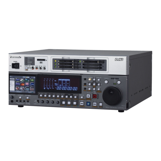
Features The AJ-HPD2500 is a memory card recorder equipped with six P2 card slots and a 4.3-inch color LCD monitor. It allows you to record and play back audio and video in the compressed DVCPRO HD, DVCPRO50, DVCPRO, DV and AVC- Intra formats on the six P2 cards, to edit P2 card and hard disk video data and edit using an external VTR as a player. - Page 19 PC card slot for immediate access. The P2 card is a disk. And SD memory card data can be sent by the card to semiconductor memory card that Panasonic developed for and from an FTP server. The network also enables professional AV use.
- Page 20 • Dubbing AVCCAM recorded clips onto a P2 card in the up converter for input DVCPROHD or AVC-Intra format, playlist editing of such The AJ-HPD2500 provides a built-in up/down/cross converter clips and ingesting such clips to non-linear editor. for output as standard. It also up-converts composite and SD- •...
-
Page 21: Native Recording
■ Native recording The unit provides support for native recording, a mode that records only active frames. This provides longer recording time when a VariCam, AJ-HPX2000/2100 or AJ-HPX3000 is connected to the HD-SDI IN connector. Variable frame rate (VFR) recording becomes possible by connecting a VariCam. ●... -
Page 22: Control Reference Guide
Control Reference Guide Audio and Video Controller 8 9 10 11 12 22 24 25 27 ➝Refer to “Operating the AVCHD Thumbnail Screens” POWER switch ( (page 152) Turns the power on and off. Set the switch to “|” to turn it on. Mode indicators A lamp corresponding to the currently selected mode REMOTE button (REMOTE indicator) - Page 23 COUNTER button EXT: Uses the external time code input from the TIME CODE IN connector or VITC, SLTC or Press to switch the counter display of the LCD panel. SVITC video input signals. Each press of this button changes the counter display Select in setup menu No.
- Page 24 HEADPHONES VIDEO IN (SHIFT + EDIT MODE) / AUDIO IN Connect stereo headphones to the HEADPHONES (SHIFT + VIDEO) buttons jack to monitor the sound during recording and Switch between video and audio input signals. playback. Use the headphone volume control knob to VIDEO IN: Press the VIDEO IN (SHIFT + EDIT adjust headphone volume.
- Page 25 REW/PREV button FF/NEXT button REW button FF button Press to rewind. Select the speed in setup menu No. Press to fast forward. Select the speed in setup menu 102 (FF. REW MAX). No. 102 (FF. REW MAX). PREV (SHIFT + REW) button NEXT (SHIFT + FF) button During playback or while displaying a still picture with During playback or while displaying a still picture with...
-
Page 26: Gui Operations
GUI Operations LCD Monitor Display Panel 15 17 THUMBNAIL button MENU/DIAG/OPERATION button Press this button and the button lights, and the MENU button thumbnail screen appears on the LCD monitor. Press Press this button to open the setup menu, thumbnail or again to return to the recording/playback mode and playlist menus. - Page 27 A2/A4 button [UMID] screen: Shows UMID information for the current video. Use to select target for editing in the playlist mode (audio channels 2 and 4). OPERATION (SHIFT + MENU) button ➝Refer to “Buttons Used in Playlist Operations” (page In the thumbnail and playlist screen (when no menu is 86).
- Page 28 PF1 button OUT/ALL CLIP/PF3 button In recording/playback mode, press this button after OUT button pressing the PF button to start the setup menu Use this button to perform the following functions operation registered in the PF1 button. during clip playback or when the unit is controlled externally.
- Page 29 PLAYER/SOURCE SELECT button PLAYER button Use this button to control an external device or operate a player in playlist mode. • In modes other than thumbnail or playlist mode: Switches to operation of an external device (RS- 422A). Pressing PLAY or other operation button will remote control an external device and display externally input video, audio and time code.
-
Page 30: Panel Control Unit And Card Slots
Instructions, visit the P2 support desk at the following Web ➝When using an SD/SDHC memory card for AVCHD sites. recording and playback (option), refer to “Using SD/ For English: http://pro-av.panasonic.net/ ➝When using an SD/SDHC memory card for SDHC Memory Cards” (page 72). AVCHD recording and playback (option), refer also to “Using SD/SDHC Memory Cards”... - Page 31 P2 Card Slots Insert P2 cards into these slots. Firmly insert the card until the EJECT button pops out. After inserting a card, flip the EJECT button to the right. EJECT button Use this button to remove a P2 card inserted in a P2 card slot.
-
Page 32: Lcd Panel
LCD Panel CH-1 CH-2 CH-3 CH-4 REMOTE SYSTEM VIDEO AUDIO WIDE CH-5 CH-6 CH-7 CH-8 59.94 ANALOG 1080i 720p 29.97 CMPST AES/EBU DVCPRO 23.98 SG12 Level meter TV system display Indicates the levels of audio signals for CH1, CH2, Indicates the selected TV system. Use the SYSTEM CH3 and CH4 (when setup menu No.767 (METER setting No. - Page 33 U lamp In the EE mode, this lamp lights when an input signal contains UMID information. Lights during playback when the recording contains UMID information. Goes off in the playlist mode. WIDE lamp This lamp lights when 16:9 aspect ratio (wide) data is recorded on a P2 card in SD mode.
-
Page 34: Rear Panel And Connectors Inside The Lower Front Panel
Rear Panel and Connectors Inside the Lower Front Panel Connector cover 15 16 17 *1: For how to open the connector cover, refer to “Opening the eSATA, USB HOST and USB DEVICE connector cover” (page 17). TIME CODE IN/OUT connector Cools this unit. - Page 35 through connector, the REF VIDEO IN connector is Pin No. Signal automatically terminated at 75 ohm. Connecting a cable to PLAY COMMAND this connector releases 75 ohm termination. When a cable STOP COMMAND is connected to the REF VIDEO loop-through connector, be FF COMMAND sure to connect the other end of the cable to a connector.
- Page 36 ◆ NOTE: REM(G) REM RX(X)REMOTE CONTROL • Use shielded cable for making connection to REMOTE connector. PROTOCOL RECEIVE REM COMMANDREMOTE CONTROL PROTOCOL TRANSMIT ANALOG AUDIO connectors REM RX(Y)REMOTE CONTROL Inputs and outputs analog audio signals. PROTOCOL RECEIVE CH1/CH2 IN Analog audio input connectors. REM TX(Y)REMOTE CONTROL connector: A switch permits switching the...
-
Page 37: Moving Between Screens And Menu Operations
Moving Between Screens and Menu Operations Operating Modes This unit provides the three operating modes described Recording/ Displays video and performs below. Use the THUMBNAIL and PLAY LIST buttons to select playback mode recording or playback. these modes. Lamps indicate which mode is currently Thumbnail mode Shows thumbnails of clips and engaged. -
Page 38: Menu Operations
Menu Operations In the playlist or thumbnail mode, press the MENU button to Press the MENU button to open the menu. open the menu. In the recording/playback mode, the setup menu appears. Use the cursor buttons to place the cursor on menu ➝Refer to “Setup”... -
Page 39: Using The On-Screen Keyboard
Using the On-screen Keyboard Using the Full Keyboard Using the Ten Keypad The full keyboard appears when necessary. The ten keypad appears when necessary. Move the cursor to the character you want to enter and press Move the cursor to the character you want to enter and press the SET button. -
Page 40: Using A Usb Keyboard
Using a USB Keyboard Connect a USB keyboard to the USB HOST terminal, select a full keyboard or ten keypad menu to enable input from a USB keyboard. Selecting keyboard layout Open the thumbnail screen. Press the MENU button. Use the cursor buttons to choose [THUMBNAIL] – [SET UP] –... -
Page 41: Recording, Playback And P2 Card Handling
Recording, Playback and P2 Card Handling Insert a P2 Card Flip the protruding EJECT button to the right. ◆ NOTE: • When you use this unit for the first time, be sure to set the internal clock in setup menu No. 069 (CLOCK SET) (page 175). Turn on the POWER switch of this unit. -
Page 42: P2 Card And Recording Times
● Visit the web site below and go to P2 support desk page for the 64 min. 64 min. 128 min. latest information on P2 card and SD/SDHC memory cards. 1080-30PN/ ---- Approx. Approx. For English: http://pro-av.panasonic.net/ 25PN (Native) 64 min. 128 min. 1080-24PN ---- Approx. Approx. Dividing clips over 4 GB in length (Native) 80 min. -
Page 43: Loop Rec Function
LOOP REC Function When two or more P2 card slots contain cards, the unit ◆ NOTE: records continuously by switching cards. When available • Turning the POWER switch OFF turns off the LOOP REC function space on the P2 cards has been used up, recording and it will remain off when the unit is powered up next time. -
Page 44: Preventing Accidental Deletion
Press the EJECT button to eject the P2 card. during recognition directly after insertion (when the P2 card access LED flashes orange) as this could damage it. If a P2 card by any chance is removed during access, [E-30] appears on the LCD monitor and the LCD panel displays the [AUTO OFF] warning. -
Page 45: Connections
Shown in the figure below is an example of deck-to-deck Example of Connections for Remote connections. Input the following reference signals as REF input. Control AJ-HPD2500 (source rear panel) These connections make it possible to send commands via Reference signal the remote control connector to enable remote control of 23.98 Hz mode: HD REF 47.95 Hz (interlace) -
Page 46: Recording From A Variable Frame-Rate Camera
Recording From a Variable Frame-Rate Camera Recording HD SDI Output Signals from a Variable Frame-rate Camera as 720/ 23.98p Combined with a variable frame-rate camera (VariCam: AJ- HDC27 series), the unit makes it possible to record HD SDI (720/ Make the following setup menu settings. 23.98p over 59.94p) output from the camera as DVCPRO HD or Item Setting... -
Page 47: Recording Hd Sdi Signals Output By An Hd Camera As 1080/23.98P
• The P2 card that is being recorded cannot be changed during Variable Frame Rate-Recording recording. • In this mode, the remaining P2 card capacity at 60p (50p), the To record active frames from the output of a variable frame- slowest slow-speed effect, is indicated. -
Page 48: Jog And Shuttle Operations Using The Search Dial
Jog and Shuttle Operations Using the Search Dial The search dial is used to search and check video. Each press of the dial switches it between the SHTL/SLOW mode and JOG mode. When the power is turned on, the search dial will not operate unless it is first returned to the STILL position. Jog Mode Turn the search dial. -
Page 49: Clip Management
Clip Management Thumbnail and Clip Management 15 14 9 10 11 12 13 This unit provides a thumbnail screen for managing clips. A clip is a single data item that contains video, audio, metadata and other additional information. Normally, a clip is one shot generated from the start of recording until recording stops. -
Page 50: Thumbnail Screen Names And Functions
Thumbnail Screen Names and Functions Display status Time display Display status indicates the type of thumbnails One of the following data is displayed: the TC (time displayed on the screen. code)/UB (user bit) at the start of clip recording/time of shooting/day of shooting/date and time of shooting/ ALL: All clips... - Page 51 Red indicates that a hard disk drive is Bad clip Unknown clip indicator connected but is not available. Indicates a clip that became defective because the power was shut down during recording or was (red) damaged for some other reason. Clips with the yellow bad clip indicator can sometimes be repaired.
- Page 52 Cursor operations in thumbnail screen Use the up, down, right and left cursor buttons to move the cursor. ◆ NOTE: • The search dial also allows you to move the cursor. ■ High-speed cursor movement and jumping • Hold down the SHIFT button and press the up or down cursor button to move the cursor to the first or last clip.
-
Page 53: Thumbnail Menu
Thumbnail Menu THUMBNAIL MENU THUMBNAIL ALL CLIP SAME FORMAT CLIPS SELECTED CLIPS MARKED CLIPS TEXT MEMO CLIPS SLOT CLIPS SETUP OPERATION DELETE FORMAT REPAIR CLIP RE-CONNECTION COPY EXCH. THUMBNAIL PROPERTY CLIP PROPERTY CARD STATUS DEVICES PROPERTY SETUP SYSTEM INFO META DATA LOAD RECORD USER CLIP NAME... -
Page 54: Changing Thumbnail Display
Changing Thumbnail Display The thumbnail screen can be customized to suit operating SELECTED CLIPS: Show clips selected using conditions and improve efficiency. the SET button. At this time the thumbnails Switching the type of information that is appear in selected order. displayed Use this function to change the order clips are played... - Page 55 DATA DISPLAY: Select items to appear in the time Setting items to display display (➝ refer to 6 in “Thumbnail Screen Names and Functions” The thumbnail display can be customized to suit different (page 50)). operating needs. The following describes procedures for Time code changing thumbnail display indicators and data settings.
- Page 56 Press the MENU button. PB POSITION: Set the playback start position for playback in the thumbnail screen. Use the cursor buttons to choose [THUMBNAIL] – RESUME From the position where playback was [SET UP] – [PROPERTY DISP.]. stopped THUMBNAIL From the time code of thumbnail position START From the start time...
-
Page 57: Thumbnail Editing
Use the cross cursor buttons to select the clip where Thumbnail Editing you want to replace a thumbnail. Use the following procedure for editing thumbnails. Editing thumbnails by adding a text memo Attach a text memo to video you want to edit. ➝Refer to “Attaching Text Memos”... -
Page 58: Selecting Clips
Selecting Clips Select clips for processing in the thumbnail screen as Canceling a selection described below. Place the cursor on a selected clip and press the SET button again. This cancels the selection. ◆ NOTE: • Hold down the SHIFT button and press the EXIT button to cancel all the made selections. -
Page 59: Playing Back Clips
Playing Back Clips • Pressing the REW button instead of the PLAY button results in rewind playback, while pressing the FF results in fast forward playback. • Pressing the STOP button during clip playback, stops playback and the thumbnail screen appears. •... -
Page 60: Playing Back Single Clips
Playing Back Single Clips To play back the clip at the cursor location, hold down the SHIFT button and press the PLAY button. Open the thumbnail screen. Use the cursor buttons to select the clip you want to play back. Press the 1 CLIP PLAY (SHIFT + PLAY) button. -
Page 61: Attaching Text Memos And Shot Marks
Attaching Text Memos and Shot Marks A text memo can be attached in a clip to mark a specific Press the MENU button and choose [THUMBNAIL] – location. The user can attach shot marks to distinguish clips [TEXT MEMO CLIPS] from the thumbnail menu. from each other. -
Page 62: Attaching Shot Marks
When the cursor is in the lower half of the LCD Attaching Shot Marks monitor, use the right and left (b/a) cursor buttons to go to the thumbnail text memo you want to play back Attach shot marks to distinguish clips from each other. and press the PLAY button. -
Page 63: Copying Clips
Copying Clips Clips can be copied to a P2 card in any slot, a hard disk or FTP ◆ NOTE: server. • To interrupt copying, press the SET button or the CANCEL (SHIFT + EXIT) button to cancel the operation. ◆... -
Page 64: Deleting Clips
Deleting Clips Use the following procedure to delete a defective clip from a P2 card. Open the thumbnail screen. Select the clip to delete. Press the MENU button. Use the cursor buttons to choose [OPERATION] – [DELETE] and press the SET button. Select [YES] and press the SET button. -
Page 65: Repairing And Reconnecting Clips
Repairing and Reconnecting Clips on multiple cards are separately copied to a hard disk and then Repairing Bad Clips copied back to a P2 card. • When a 5-minute or longer DVCPRO HD or AVC Intra100 clip (10- minute or longer DVCPRO50 or AVC Intra50 and 20-minute or longer This section describes how to restore bad clips that have DVCPRO or DV clip) is copied to a hard disk drive and later written been damaged due sudden power outages during recording... -
Page 66: Viewing And Revising Clip Information
Viewing and Revising Clip Information Information added to clips Viewing Clip Information Indicates the number of indicators, attached text memos and voice memos in a clip. The mark appears when Detailed clip information can be displayed on the screen. the P2 card where the clip resides is write-protected. Open the thumbnail screen. -
Page 67: Revising Clip Metadata
USER CLIP The name a user assigns to a clip. Revising Clip Metadata NAME: This normally includes a GLOBAL CLIP Use the steps below to revise clip metadata. VIDEO: Video signal system (FRAME RATE, PULL DOWN, Display clip metadata. ASPECT RATIO) AUDIO: Audio channel system and other Use the cursor buttons to select the metadata you... -
Page 68: Attaching Metadata To Clips
P2 viewer allows you to use a PC for processing clips recorded on a P2 card. Download the latest version of P2 viewer from the URL given below. For English: http://pro-av.panasonic.net/ Install P2 viewer on a PC, create a metadata upload file and write it to an SD memory card. -
Page 69: Loading Set Metadata Values
■ Incrementing the counter value of the USER Counter value CLIP NAME for clips exceeding 4 GB In the following case, one shot is recorded as multiple clips The counter value is indicated as a four-digit number. When and the counter value is automatically incremented and recording method “TYPE 2”... - Page 70 Use the cursor buttons to select [META DATA] – Use the cursor buttons to move the pointer and press [LOAD] and press the SET button. the SET button. The metadata name of the metadata upload file on the SD Use this function to check loaded metadata settings. memory card appears.
-
Page 71: Recording Clips Containing Metadata
Press EXIT to exit the metadata confirmation dialog. Select [ON] and press the SET button. This setting records the loaded metadata simultaneous Deleting metadata with video recording. The USER CLIP NAME is attached to metadata as specified by the recording method. Use the following procedure to delete metadata stored in this unit. -
Page 72: Using Sd/Sdhc Memory Cards
Using SD/SDHC Memory Cards This unit can use SD and SDHC memory to store setup menus, recorded metadata and AVCHD recordings *1: Requires AVCHD codec board (optional accessory). ◆ NOTE: • Further information on the above functions is provided in the following sections in this manual. - Page 73 Select [YES] and press the SET button. The card is now formatted. ◆ NOTE: • To cancel formatting, select [NO] and press the SET button. • Check that no important data remains on a card before formatting since data erased by formatting cannot be recovered.
-
Page 74: Formatting P2 Cards
Formatting P2 Cards Formatting Individual P2 Cards Formatting All P2 Cards Open the thumbnail screen. Open the thumbnail screen. Press the MENU button. Press the MENU button. Use the cursor buttons to choose [OPERATION] – Use the cursor buttons to choose [OPERATION] – [FORMAT] –... -
Page 75: Checking Card Status
Checking Card Status Use the following procedure to display P2 card slot status and P2 card usage and other card information on the screen for checking. Selecting Information to Display Select whether remaining capacity or used capacity should appear in the P2 card information. Open the thumbnail screen. -
Page 76: Displaying Card Status Information
Displaying Card Status Information After completing the settings described on the previous page, Write protect mark you can use the procedure described below to check the A write-protected P2 card is indicated by the mark status of P2 cards in P2 card slots. displayed here. - Page 77 Card warning messages This warning appears when the following P2 cards are inserted. [RUN DOWN CARD] The maximum number of overwrites has been exceeded. [DIR ENTRY NG CARD] The P2 card directory structure is not supported. Open Detailed P2 Card Status for more information on this warning.
-
Page 78: Editing Playlist Function
Editing Playlist Function This unit allows the user to create a playlist that combines the desired audio and video sections recorded on a P2 card. The user can play back the clip sections on the playlist to check what the created footage will look like after editing. Sections of audio and video selected for playback are referred to as an event and a list of such events is called a playlist. -
Page 79: Editing Workflow
Editing Workflow Playlist mode uses a player and a recorder to create a playlist Press the PLAYER button to switch to player (left that stores editing results. side) operations. The PLAYER button goes on during player operation. Player The player thumbnails or playback video appear on the left side of the playlist screen. -
Page 80: Insert Editing Mode And Overwrite Editing Mode
Insert Editing Mode and Overwrite Handling of Sections without Audio Editing Mode and Video In playlist mode, events can be added either in insert editing Overwrite editing can generate sections on the timeline mode or in overwrite editing mode. missing both audio and video. When played back, sections Use the EDITMODE button to switch between the two modes. -
Page 81: Names And Functions Of The Playlist Screen
Names and Functions of the Playlist Screen The picture below shows that the playlist interface is made up of four elements. Recorder screen Player screen Timeline Data bar Player screen The player screen consists of the player thumbnail screen that shows thumbnails and the player playback screen that shows player video . - Page 82 DUR: Indicates the duration between the set Green Indicates the rough location of the IN IN and the OUT points on the player triangle (a): point when a player IN point is set. when the IN and OUT buttons are ◆...
- Page 83 OUT: Indicates the time code of the OUT Audio channel 3 point set on the recorder when the OUT Audio channel 4 button is pressed. • Selected status DUR: Indicates the duration between the set IN and OUT points of the recorder Orange: Selected track when the IN and OUT buttons are...
- Page 84 - SET button Mark indicating change in audio level Selecting and deselecting an event at cursor location. This mark appears on events to indicate that a change - Hold down the SET button for 1 second or longer in audio level has occurred, but only if the event has Selecting the same IN/OUT events at the cursor location.
- Page 85 Playlist file name indication Names of playlist files are indicated in white. Gray file name: Indicates read-only files. Red file name: Indicates that the P2 card storing the file has not been inserted. ◆ NOTE: • When a card does not contain files, white “------” appears. Editing: Playlist Function...
-
Page 86: Buttons Used In Playlist Operations
Buttons Used in Playlist Operations 1312 14 7 9 15 17 16 8 18 19 Cursor buttons (▲ / ▼ / b / a) PLAY LIST button Press to engage the playlist mode to create playlists or • During recorder operation play back created playlists. - Page 87 • During player thumbnail operation SOURCE SELECT (SHIFT + PLAYER) button These buttons move the cursor in the same way as the Press this button and select a player from the devices thumbnail screen. (interfaces) listed in the menu that appears. Select a ➝Refer to “Cursor operations in thumbnail screen”...
- Page 88 EDIT MODE button IN/SLOT CLIP button Press this button to toggle between insert and OUT/ALL CLIP button overwrite editing. IN/OUT button Hold down the IN or OUT button to superimpose on the GO TO/A. DUB MODE button monitor the time code of IN or OUT point set on the GOTO button player and recorder.
- Page 89 REC button REC/UNITY/PB selection switch and audio level controls Finalizes an edit operation, registers the event and displays it on the timeline. Imports video to a P2 card Select recording (REC position) or playback (PB from an external device (RS-422A) or hard disk used position) by the selection switch and adjust the levels as the player.
-
Page 90: Preparing For Playlist Creation
Preparing for Playlist Creation Select [ON] and press the SET button. This chapter will describe the setup required prior to creating playlists. This setting replaces the time code during playback. ◆ NOTE: Setting System Frequency • When set to [OFF], the time code is not replaced, instead the time code of each clip is output. -
Page 91: Creating A New Playlist
Setting Auto Entry Changing audio channel content When Auto Entry is enabled, after confirming edit using the You can replace audio content that will become available PREVIEW or REC button, the IN point of the recorder is when creating events. automatically set to the location after the last frame in the edited section. -
Page 92: Naming Playlists
Select [YES] and press the SET button. This registers an event where the start of the clip is the IN point and its end is the OUT point. Naming Playlists Use the steps below to name playlists. Press the PLAY LIST button to open the playlist screen. -
Page 93: Creating Playlists
Creating Playlists Press the PLAY LIST button to open the playlist Registering Events in a Playlist screen. To register an event in a playlist, either set IN and OUT points Press the SOURCE SELECT (SHIFT + PLAYER) using the player and the recorder, or select clips from the button. - Page 94 Press the THUMBNAIL button to switch to player Switching between player and recorder video. The THUMBNAIL button goes off and the screen shows the video of the player. Press the PLAYER button to switch to recorder operations. The PLAYER button goes off and the right side of the screen appears in a yellow frame.
- Page 95 ◆ NOTE: Limiting the number of clips used as a • To select specific clips as a player, select clips to be used from player the player thumbnails and select [SELECTED CLIPS]. The clips then appear in the order they were selected. The player is normally composed of all clips on a P2 card that •...
- Page 96 Set the OUT point of the player. • When the IN and OUT points of the player spans multiple clips, multiple events are created. While looking at the player screen, hold down the OUT button and press the ENTRY button at the end location of 00:00:01:15 the required section to set the player OUT point.
- Page 97 Revising IN and OUT points for the player Preview and assigning events (when the and recorder player is a P2 card) After setting the IN or OUT point, preview to check edit result on the recorder. 2,3,4 Switch to player or recorder operation. Press the PLAYER button to switch to player or recorder Press the PREVIEW button to preview.
- Page 98 The event is recorded and appears on the timeline. Preview and assigning events (when the player is something other than a P2 card) After setting the IN or OUT point, preview to check edit result on the recorder. ◆ NOTE: •...
-
Page 99: Registering Events By Clip
• The selected clip will be inserted even when the overwrite Registering Events by Clip editing is active. Revising Registered Events Use the following procedure to add selected clips to the playlist. This operation registers the start of a clip as the IN Events registered on the timeline can be revised. - Page 100 Press the ENTRY button to finalize trimming. ◆ NOTE: • Performing any of the following operations will discard the changes and redisplay the playlist screen. - Pressing the EXIT button - Pressing the CANCEL (SHIFT + EXIT) button • You cannot make changes that go beyond the start and end points of the source clip.
- Page 101 Cutting events Moving events Events can be cut (divided) at the recorder playback location Selected events can be moved. V, A1 to A4 events whose IN (indicated by the yellow bar on the timeline). and OUT points are aligned on the timeline can be moved. The destination is also limited to events at V and A1 to A4 cursor location with IN points.
-
Page 102: Switching Audio Channels
Deleting events Deleting all events Selected events can be deleted. The result of a deletion You can use the following function to delete all events in a depends on whether the operation was performed in insert or playlist. This operation differs from creating new playlists overwrite editing. -
Page 103: Saving A Playlist To A P2 Card
Select an event. Press the MENU button. Select the event where audio channels should be switched. Multiple events can be selected. Use the cursor buttons to choose [FILE] – [SAVE AS] and press the SET button. Set the channel. Press the MENU button, choose [SETTING] – [AUDIO CH] from the menu and set the channels to be input to each channel. -
Page 104: Opening A Playlist File
Use the cursor buttons to choose [FILE] – [OPEN] and press the SET button. Use the cursor buttons to select the number of the P2 card slot containing the file to import and press the SET button. Press the PLAY LIST button to open the playlist screen. -
Page 105: Deleting Playlist Files
Deleting Playlist Files Use the steps below to delete a playlist files stored on a P2 ◆ NOTE: card. • Press the MULTI SEL (SHIFT + SET) button to quickly select continuous files. Then all files from the file previously selected Press the PLAY LIST button to open the playlist by pressing the SET button to the cursor location where the MULTI SEL button was pressed will be selected. -
Page 106: Recording Voice-Overs
Recording Voice-Overs This function allows you to make voice-overs and use them in editing. Recording can be performed on one or two channels. It is also possible to mix input sound with playback sound. Voice-overs are displayed on the timeline as an audio event. ◆... -
Page 107: Voice-Over After Assigning The In And Out Points
Voice-Over after Assigning the IN Starting voice-over recording and OUT Points Find the starting point of the voice-over, and press the IN + ENTRY button. Press the PLAY LIST button to open the playlist Use the operation buttons or the search dial to find the screen. -
Page 108: Revising Voice-Overs
Voice-over from playback status Find a location before the starting point of the voice- over. Use the operation buttons or the search dial to move to a location before the starting point of the voice-over. Use the PLAY button to start playback. Hold down the REC button and press the PLAY button where you want to start a voice-over. -
Page 109: Setting Audio Level
Setting Audio Level A fixed or variable audio level can be set for a specified section of the playlist. Review or playlist playback occurs at the set audio level while Edit Copy generates material at the set audio level. The audio level can be bet set when registering an event or for a specific audio section of already existing playlist. ◆... -
Page 110: Changing Audio Level In An Event During Event Registration
• Pressing the STOP button to interrupt preview makes settings valid Changing Audio Level in an Event until stopping. Audio level after the interruption point in the event is set to the same level as the interruption point. during Event Registration Setting Audio Levels for Specific When registering a new event in a playlist, change the audio level during the registration of the event. - Page 111 Check audio level by performing a review or playlist playback. A review after setting the IN and OUT points in an event and changing the audio recording level will play back the event from start to end. To perform a playback check only of the section where the audio recording level was changed, press the SEEK TO IN POINT (IN + GOTO) button and playback will start after locating the IN point.
-
Page 112: Viewing Event And Clip Information
Viewing Event and Clip Information Event information Event Property Indication • IN point, OUT point thumbnails (video that corresponds to the IN and OUT points in the source material for audio The EVENT PROPERTY dialog provides a variety of event) and time code values information on the event at the cursor location. - Page 113 Use the cursor buttons to select the thumbnail that you want information about. Press the MENU button. Use the cursor buttons to choose [PROPERTY] and press the SET button. ◆ NOTE: • You can also press the PROP (SHIFT + TC PRESET) button instead of performing the operations provided after step 3.
-
Page 114: Playing Back Playlists
Playing Back Playlists Playing Back Playlists Reviewing Events Follow the steps below to play back a playlist. Use the steps below to play back and check the event at the cursor location. Press the PLAY LIST button to open the playlist Press the PLAY LIST button to open the playlist screen. -
Page 115: Creating New Clips From The Playlist (Edit Copy)
Creating New Clips from the Playlist (Edit Copy) Edit Copy is a function that allows you to use the playlist to create new clips. ◆ NOTE: • The user can set a time code for playback that will be used as the start value for the time code for a clip created using Edit Copy. If necessary, set the time code at playback prior to an Edit Copy. -
Page 116: Connections Using Usb Or Esata Connectors
Use of P2 viewer, which can be downloaded from the following site, allows you to manipulate clips stored on a P2 card on a Windows PC. For English: http://pro-av.panasonic.net/ USB2.0 ◆ NOTE: • For details regarding connections, refer to the Operating Instructions supplied with the PC and the application software. -
Page 117: Connecting A Pc To This Unit
Connecting a PC to This Unit Switching to USB Device Mode Press the MODE (SHIFT+REMOTE) button to return to regular mode. ◆ NOTE: • Recording and playback are not available in the USB device mode. • In the playlist mode, the MODE (SHIFT+REMOTE) button is not available during remote operation. -
Page 118: Using This Unit With A Hard Disk
Using This Unit With a Hard Disk Supported Hard Disks This unit supports the following hard disks types. • Panasonic portable hard disk unit P2 store (AJ-PCS060G) • A hard disk that supports the USB 2.0 interface • A hard disk that supports the eSATA interface ◆... - Page 119 • A hard disk is a high-precision instrument whose read and write functions may fail if used in an unsuitable environment. Please note that Panasonic accepts no liability whatsoever for data loss or other losses either direct or indirect arising from hard disk damage or other defects.
-
Page 120: Formatting Hard Disks
Select [YES] in the confirmation message that Formatting Hard Disks appears and press the SET button. Follow the steps below to initialize a hard disk in a TYPE S or When the confirmation message appears again, FAT format. select [YES] and press the SET button. The hard disk will now be formatted. -
Page 121: Copying Clips To A Hard Disk
URL listed below. This allows you to mount the specified folder when a hard disk is connected to a Windows For English: http://pro-av.panasonic.net/ When the export operation ends, “COPY COMPLETED!” appears. -
Page 122: Displaying Hard Disk Information (Explorer Screen)
Select the location of the clip in the hard disk folder Use the cursor buttons to select [HDD] (USB or or partition list that appears and press the SET eSATA)] – [EXPLORE] and press the SET button. button. ◆ NOTE: •... -
Page 123: Hard Disk Operations
Partitions or holders are selected and changes to Partition information (for a TYPE S hard disk or P2 store disk) Check marks appear for selected partition. NUMBER (NO.): Partition number (1 - ) MODEL: P2 card model name PARTITION Name assigned to partition NAME: (➝... -
Page 124: Importing Data From A Hard Disk To A P2 Card
Press the ENTRY button to confirm the name. Importing Data from a Hard Disk to a P2 Card Importing data by partition (TYPE S hard disks and P2 Store disks only) Use the steps below to import data (load data from a hard disk to a P2 card) by partition (by P2 card) to a P2 card that has the same capacity as the source card. -
Page 125: Displaying Clip Thumbnails On A Hard Disk
Select [YES] and press the SET button. Displaying Clip Thumbnails on a The data will now be imported. Hard Disk When the import operation ends, the message “COPY COMPLETED” appears. You can display thumbnails and manage clips stored on the ◆... - Page 126 Hard disk information SERIAL: P2 card serial number MODEL: P2 card model name SELECTED A check mark appears for the PART.: selected partition. SELECTED This indication appears only when PART. No.: multiple partitions are selected and a list of numbers of selected partitions is displayed.
-
Page 127: Viewing Hard Disk Clip Information
Viewing Hard Disk Clip Information Playing Back Audio and Video of Hard Disk Clips for Confirmation Use the steps below to view a variety of metadata on clips stored on a hard disk. It shows information in the same way as Open the hard disk thumbnail screen. -
Page 128: External Remote Control
External Remote Control Remote Operation of External Devices Use the RS-422A interface to send commands to an external Indications during control of external device to control it. devices The following functions permit remote control. • PLAY, STOP, SEARCH, FF, REW In external control mode, the PLAYER lamp goes on and the •... -
Page 129: Automatic Recording Of Cards
Automatic Recording of Cards Registering IN and OUT points makes possible automatic recording (AUTO CAPTURE) between those two points. Enter the mode that permits control of external devices. Press the PLAYER button when the unit is in the recording/ playback mode. Select an area for capture. -
Page 130: Connecting This Unit To A Network
Connecting This Unit to a Network The network connector (1000Base-T, 100Base-TX, 10Base-T) allows you to connect the unit to a network to transfer clips to network servers, browse Web sites, launch network services to use them. (Functions) • FTP client function enables the unit to send and receive clips •... - Page 131 Setting: Item Description Set value Factory defaults MAC ADDRESS MAC ADDRESS (unique ID) Cannot be changed. Set value (cannot be changed) DHCP DHCP setting ENABLE: Uses DHCP (automatic assignment) DISABLE DISABLE: Does not use DHCP (automatic assignment) IP ADDRESS IP address Enter using the ten keypad 192.168.0.2 SUBNET MASK...
- Page 132 SET button to set it. Item Description Setting Initial value HOSTNAME Host name Enter using the full keyboard. AJ-HPD2500 (up to 31 characters) FTP server setting ENABLE: Starts up FTP server. ENABLE DISABLE: Does not start up FTP server.
- Page 133 ■ Changing password and deleting user User settings for server service Move the cursor to the user whose password is to be Select [USER LOGIN SETTING] and open any of the following changed or deleted. screens to make the required settings. ■...
- Page 134 ■ Opening the connection log (LOG) Use the cursor buttons to select [YES] when the message [SURE?] appears and press the SET Open the thumbnail screen. button. ■ Saving settings to an SD memory card Press the MENU button to open the menu. Open the network screen.
-
Page 135: Using Ftp Client Functions
Gray: Gray indicates that the LAN is set Using FTP Client Functions to off. White: White indicates that the LAN is Use of FTP client functions requires LAN and FTP client set to on. settings. Yellow: Yellow indicates that a LAN cable is connected and that the List of FTP server folders (FTP explorer network is running. -
Page 136: Displaying Clip Thumbnails On The Ftp Server (Ftp Thumbnail Screen)
• An error may be generated when network operations are ◆ NOTE: performed right after connecting a LAN cable or when a • Pressing the SET button in the CONTENTS folder will not display previous operation was interrupted. thumbnails. Be sure to press the SET button in folders above the •... -
Page 137: Deleting Clips On The Ftp Server
Deleting Clips on the FTP Server Transferring clips to the FTP server (export copy) Clips on the FTP server that are no longer necessary can be Open the thumbnail screen to select a clip to transfer deleted in the same way as clips on P2 cards. ➝Refer to “Deleting Clips”... - Page 138 Writing back clips from the FTP server (import copy) Use the steps below to write back selected clips from an FTP server on the network to a P2 card or hard disk. Open the FTP thumbnail screen. Select the clip to copy from the thumbnails displayed on the server.
-
Page 139: Transferring Sd Memory Card Data
Press the SET button to start exporting. Transferring SD Memory Card Data ◆ NOTE: • The number of files, their size, network status and other Use the steps below to transfer data from an SD memory card conditions may lengthen the time required for exporting. to an FTP server or write back data from an FTP server to an •... -
Page 140: Using Server Functions
“LAN” appears on the screen after switching modes. To return to normal operating mode, press the MODE (SHIFT+REMOTE) button again. “MAIN MODE” will appear to indicate that you have returned to the normal operating mode. ◆ NOTE: • Operations including recording and playback are not available in server mode. -
Page 141: Using Browser Functions
Clips with proxy data appear in a light red cell. Clicking HTTP server service such thumbnails starts playback of proxy data. This service allows you to access this unit using any of a ◆ NOTE: variety of browsers from a PC. •... - Page 142 The browser screen appears on the screen after • Some Web page content may generate system errors (E-37, E-38, etc.). Should this happen, turn the power off and then turn switching modes. it back on again. • Download functions on Web pages cannot be used. •...
- Page 143 ■ Operations from USB keyboard Connect a USB keyboard to control the browser. Direction keys and Move link focus. TAB key: ENTER key: Use to confirm settings. Description [Alt]+[Home] Displays the home page. [Alt]+[left] Returns to the previous page. [Alt]+[right] Proceeds to the next page.
-
Page 144: Rs-232C Interface
RS-232C Interface An RS-232C interface connection with a PC makes it possible to operate this unit via commands. Conditions for receiving commands Send Format via an RS-232C interface RS-232C Interface • The front panel REMOTE button is on. • If the above condition is not met, [ACK] + [STX] ERR001 [ETX] is returned to external devices. - Page 145 ■ When data is incorrect or an error has occurred Return format in the deck Returns a reception completed message. RS-232C Interface [ACK] Returns an error code. [STX] [ERN [ETX] Error code The following responses are made to a command. If Error code list necessary, more than one response may be made.
- Page 146 Command table Operation control commands ◆ NOTE: • The initial [STX] and final [ETX] codes in send commands and return (completion) messages are not included in the table. • A return (completion) message returns [ACK] when data is received. Then an execution message is returned. The execution messages are described in the table below.
- Page 147 Question commands ◆ NOTE: • The initial [STX] and final [ETX] codes in send commands and return (completion) messages are not included in the table. • A return (completion) message returns [ACK] when data is received. Then an execution message is returned. The execution messages are described in the table below.
-
Page 148: About The Clip Select Function
Clip Select Function About the Clip Select Function Use the clip select function to play back only one clip. ◆ NOTE: Clip Select Setting • The clip select function is available when setup menu No.25 (SYSTEM FREQ) is set to 50 or 59.94. •... -
Page 149: Using An Optional Avchd Board
SD memory 8 MB Cannot be used. Can be used. cards 16 MB • Use of the Panasonic SD memory cards, miniSD memory 32 MB - Normal operation is cards and microSD cards is recommended. 256 MB not guaranteed. Be sure to format SD memory cards on this unit. - Page 150 Select [YES] in the screen shown below that appears. To Clips recorded on SD memory cards inserted in the SD/SDHC cancel formatting, select [NO]. memory card slot on the AJ-HPD2500 can be played back as thumbnails and video clips corded on P2 cards. ■ Access lamps...
- Page 151 Recovery of SD memory cards Do not remove an SD memory card or turn the power off when the SD memory card access lamp is blinking. If an SD memory card is accidentally removed when the SD memory card access lamp is blinking or the power is turned off during recording or in the final phase of recording, turn the power on again, switch to AVCHD mode to open a screen that prompts you to repair the clip.
-
Page 152: Operating The Avchd Thumbnail Screens
Operating the AVCHD Thumbnail Screens Screen configuration This mainly involves regular AJ-HPD2500 operations and AVCHD (optional) operations. Screen configuration is shown below. AVCHD clips are played back from the AVCHD mode thumbnail screen. Normal mode PLAY THUMBNAIL THUMBNAIL MODE (SHIFT... - Page 153 ■ Opening menus Switching to AVCHD mode Press the MENU button when thumbnails are displayed. Use the steps below to switch to AVCHD mode. Press the MODE (SHIFT+REMOTE) button to open the mode select menu. ◆ NOTE: 2) 3) • AVCHD display and selection are available only when setup menu No.
-
Page 154: Thumbnail Setup
Press the up and down (4/5) cursor buttons to select Clip no. an item and press the SET button. Indicates the order clips were recorded (up to 1000 clips). The number of clips recorded in a different format or that for some other reason cannot be played back are indicated in red. -
Page 155: System Info
DELETE: Deleting and protecting clips Deletes Clips. (OPERATION) ALL CLIPS: Deletes all clips. Select [YES]/[NO] and press the SET button. Use the steps below to delete or protect clips. SELECT: Deletes selected clips. Select [SELECT:], Press the MODE (SHIFT+REMOTE) button to switch press the SET button, move the cursor to the clip you want to select, and then to the AVCHD mode. - Page 156 CARD STATUS: Formatting card, checking clip and card SD memory card information appears. information (CARD FUNCTIONS) Use the steps below to format SD memory cards and check clips and SD card information. Press the MODE (SHIFT+REMOTE) button to switch to the AVCHD mode. ➝Refer to “Switching to AVCHD mode”...
- Page 157 *1: AVCCAM Viewer can be downloaded from the site listed location) below. • LONGITUDE (longitude of shooting For English: http://pro-av.panasonic.net/ location) • LATITUDE (latitude of shooting To clear the clip metadata screen, press the left (b) cursor location) button.
- Page 158 CARD READ: Uploading metadata (META DATA) Loads metadata stored on an SD memory card into this unit. Select whether or not you want to load the data In addition to uploading metadata, use this function to perform ([YES]/[NO]) and press the SET button. This unit can show the operations listed below.
-
Page 159: Setting Up For Playback
USER CLIP NAME to be recorded Press the up and down (4/5) cursor buttons to select • When clip metadata is loaded playback format and press the SET button. TYPE1: Loaded data TYPE2: Loaded data + counter value • When clip metadata is not loaded or when loaded clip metadata is not to be recorded TYPE1: A 5-digit serial number assigned in... -
Page 160: Playing Back Avchd Clips
To turn off resume playback, set to [OFF] in step 4. Slow/fast forward/rewind ◆ NOTE: Use the search dial during playback or pause to select • A change in setting will not change the resume playback setting playback speed. of a P2 card. Press the PLAY button to return to normal playback. - Page 161 Set the time code. ◆ NOTE: Use the TCG switch to set INT REGEN, INT PRESET or • During dubbing, recording does not start from the beginning of EXT. If EXT is set, recording of TC and UB values on an SD memory card.
-
Page 162: Recording Avchd To An Sd Memory Card
Recording AVCHD to an SD Memory Card SD memory card recording time (SD memory card recording time (estimate)) Recording mode SD memory card capacity (Highest image quality (High image quality mode/ (Standard image quality (Long playing mode/1440 x 1920 x 1080 pixels) mode/1920 x 1080 pixels) 1080 pixels) mode... -
Page 163: Recording Remote Input Signals
Recording P2 card material in AVCHD Recording remote input signals To make a recording in AVCHD from a P2 card, perform the External signals are simultaneously recorded to a P2 card and required clip editing in playlist mode and play back the final an SD memory card. -
Page 164: Unit Setup
Setup Unit Setup The settings for this unit consist of SYSTEM, BASIC, OPERATION, INTERFACE, EDIT, TIME CODE, VIDEO, AUDIO, LCD and MENU. The SYSTEM setting values are stored in the SYSTEM file. The other setting values are stored in the user setting file. Up to five user files (USER1 to USER5) can be saved. -
Page 165: Changing Settings
Changing Settings The menus superimposed on the LCD monitor and a monitor (when the SUPER switch on the upper front panel is set to “ON”) connected to the MON OUT, SD SDI MON OUT or SDI OUT connector make it possible to change settings. Superimposed information to the output connectors can be selected in setup menu No.005 (SUPER). -
Page 166: Using A Lock To Protect The User Setting File
You can assign four of the items that are most often changed Press the PF button (1 to 3) required to bring up the to the PF buttons to enable quick changes of the setting item to change. values. Each press of the button updates the setting value. Assign a setting item to the PF button and perform the following operation to change setting values. -
Page 167: Setup Menu
Setup Menu SETUP MENU SYSTEM ENCODER SEL (➝page 169) 001 LOCAL ENA SYS H(HD) 002 CTL DISP SYS SC(SD) BASIC 003 REMAIN SEL SYS H(SD) (➝page 171) 005 SUPER SCH COAR(SD) 006 DISPLAY SEL SCH FINE(SD) 007 CHARA H-POS AV PHASE 008 CHARA V-POS SYSTEM FREQ 009 CHARA TYPE... - Page 168 VIDEO 601 VIDEO INT SG (➝page 183) 602 SDI IN MODE 620 DOWNCON MODE AUDIO 701 CH1 IN LV 621 UPCONV MODE (➝page 187) 702 CH2 IN LV 626 D/C ENH H 706 CH1 OUT LV 627 D/C ENH V 707 CH2 OUT LV 638 IN U/C MODE 710 MONIL OUT LV...
-
Page 169: Item Settings
Item Settings SYSTEM The system menu specifies HD SDI and SD SDI outputs, analog composite output, phase adjustment of audio output, system frequency, phase of SD REF input of HD SDI output, and system file lock. • XX indicates factory default settings. Item Setting Settings and brief function description... - Page 170 Item Setting Settings and brief function description SUPER SUPER DISP. DISP. 0000 –32 only 59.94Hz 50Hz 29.97Hz 25Hz 60-25Hz Adjusts the SCH phase of analog composite output (total variable range ±45° or more). 0032 SCH FINE(SD) Changes the SC phase but not the H phase. Covers ±180°...
-
Page 171: Basic
Video Output Signal Adjustments The control matrix for adjustments is shown below. When CMPNT is selected in setup menu No. 650 (STYLE) When CMPST is selected in setup menu No. 650 (STYLE) Setting Adjustment Setting Adjustment 05: ENCODER SEL 653: Y LVL 05: ENCODER SEL 662: V LEVEL 654: Pb LVL... - Page 172 Item Setting Settings and brief function description SUPER SUPER DISP. DISP. 0000 59.94Hz 50Hz 23.98Hz 29.97Hz 59-23Hz 25Hz 0001 LCD&M 60-25Hz only 0002 Specifies whether superimposed information will be output to VIDEO/SD SDI MON or SDI OUT. 0: Not output (LCD monitor only) 1: Output to LCD monitor and VIDEO MON, SD SDI MON SUPER 2: Output to LCD monitor and VIDEO MON, SD SDI MON, SDI OUT...
- Page 173 Item Setting Settings and brief function description SUPER SUPER DISP. DISP. When set to 59.94 Hz only 59.94Hz 50Hz 29.97Hz 59-23Hz 25Hz 0000 1080i Specifies the recording format used by this unit. 0001 720p 0: 1080i mode (when set to 59.94 Hz, 50 Hz)/1080p mode (when set to 29.97 Hz, 0002 480i 59-23 Hz, 25 Hz)
- Page 174 Item Setting Settings and brief function description SUPER SUPER DISP. DISP. When set to 59.94 Hz 59.94Hz 50Hz only 0000 SYSFMT Specifies the format used by the playlist. 0001 30PN <In the DVCPRO HD format> 0002 24PN 0: Format set in setup menu No. 020 (SYS FORMAT) and No. 025 REC FMT (HD). 1: 720/30PN (when set to 59.94 Hz)/720/25PN (when set to 50 Hz) When set to 50 Hz 2: 720/24PN...
- Page 175 Item Setting Settings and brief function description SUPER SUPER DISP. DISP. 0000 Specifies whether or not to make loop recording. ➝For details, refer to “LOOP REC Function” (page 43). 0001 0: Does not make loop recording 1: Makes loop recording LOOP REC NOTE: Turning the power off cancels this setting.
- Page 176 Item Setting Settings and brief function description SUPER SUPER DISP. DISP. 0000 Sets the hour. HOUR Set the hour according to the 24-hour clock. 0023 0000 Sets the minute. MINUTE 0059 0000 00:00 Sets the time difference from the world standard time. Use the table below for reference in setting the time.
-
Page 177: Operation
OPERATION This menu allows you to set method for engaging search dial operations, maximum shuttle speed operation, maximum speed of FF and REW operation, NEXT and PREV seek operations, display of warning messages when REF.VIDEO is not connected, PLAY delay time, display of warnings when power is too low, voltage when the power supply is turned off. •... - Page 178 • When set to something other than OFF, “AREC” is displayed on the first line of the superimposed information screen. • Press the REMOTE button to turn the button on. Refer to “Panasonic camera- recorders, recording formats and recording/stopping signals (Recording Mark)” on this page before selecting TYPE1 or TYPE2.
-
Page 179: Interface
ID SEL NOTE: • Select [OTHER] for ID data for a VTR other than a DVCPRO. • Select [ORIG] only when specific Panasonic controllers (such as AJ-A850, separately sold accessory) are connected. 0000 Determines whether or not REMOTE connector commands should be extended to the clip select function and the LAN and USB switching function. -
Page 180: Edit
EDIT This function determines unit mode after a cue-up operation. • XX indicates factory default settings. Item Setting Settings and brief function description SUPER SUPER DISP. DISP. 0000 STOP Selects unit mode after cue-up operation. 0001 STILL 0: STOP mode AFTER CUE-UP 1: Still picture (SHTL +0.0) mode 0002... - Page 181 Item Setting Settings and brief function description SUPER SUPER DISP. DISP. When set to 59.94 Hz, Specifies the position where the VITC signal will be inserted. 29.97 Hz, 23.98 Hz, NOTE: 24 Hz, 59-23 Hz, • You cannot select the same line as in setup menu No. 501 (VITC POS-1). 60-24 Hz •...
- Page 182 Item Setting Settings and brief function description SUPER SUPER DISP. DISP. 0000 only 59.94Hz 29.97Hz 0001 Sets the DF or NDF mode for CTL and TCG. DF MODE 0: Uses drop frame mode. 1: Uses non-drop frame mode. 0000 VOUT only 59.94Hz 50Hz...
-
Page 183: Video
VIDEO This menu is used for video settings. • XX indicates factory default settings. Item Setting Settings and brief function description SUPER SUPER DISP. DISP. 0000 100%CB Sets the internal signal type. SMPTE and ARIB signals are available in HD mode only (black in SD mode). - Page 184 Item Setting Settings and brief function description SUPER SUPER DISP. DISP. When set to 59.94 Hz, only 59.94Hz 50Hz 29.97Hz 25Hz 60-25Hz 29.97 Hz Specifies the video signal output from the video output connector. 0000 AUTO 0: Switches output automatically depending on current recording and playback format. 0001 1080i 1: 1080/59.94i or 1080/50i...
- Page 185 Item Setting Settings and brief function description SUPER SUPER DISP. DISP. 0000 0.0% only 59.94Hz 50Hz 29.97Hz 25Hz 60-25Hz level of SD SDI and analog composite output (– ∞ to 0 dB to +3 dB). Adjusts the P Pb LVL(SD) 1000 100.0% NOTE:...
- Page 186 Item Setting Settings and brief function description SUPER SUPER DISP. DISP. 0000 BLANK only 59.94Hz 0001 THRU Turns on and off closed caption signals in the first field output from the SD SDI and analog composite output during playback. CC (F1) BLANK 0: Signals are forcibly blanked.
-
Page 187: Audio
AUDIO This menu is used for audio settings. • XX indicates factory default settings. Item Setting Settings and brief function description SUPER SUPER DISP. DISP. 0000 Specifies the standard level for audio input (CH1). 0001 CH1 IN LV 0002 –3dB 0003 –20dB 0000... - Page 188 Item Setting Settings and brief function description SUPER SUPER DISP. DISP. 0000 Specifies the input signal to be recorded on the audio CH4. 0001 0: Audio input CH1 signal 0002 1: Audio input CH2 signal 0003 REC CH4 2: Audio input CH3 signal 3: Audio input CH4 signal 0004 CH1+2...
- Page 189 Item Setting Settings and brief function description SUPER SUPER DISP. DISP. For AJ-HPD2500P Specifies the standard level. 0: –20 dB 0000 FS-20 1: –18 dB 0001 FS-18 2: –12 dB 0002 FS-12 REF LEVEL For AJ-HPD2500E 0000 FS-20 0001 FS-18 0002 FS-12 0000...
- Page 190 Item Setting Settings and brief function description SUPER SUPER DISP. DISP. 0000 59.94Hz 50Hz 23.98Hz 29.97Hz 59-23Hz 25Hz 0001 60-25Hz only Specifies whether or not the playback sound be mixed in the voice-over. 0: Playback sound is not mixed. A DUB PB MIX 1: The input and playback sound are mixed in the recording.
-
Page 191: Lcd
This menu is used for setting up the LCD monitor. • XX indicates factory default settings. Item Setting Settings and brief function description SUPER SUPER DISP. DISP. 0000 Sets LCD protect mode. 0001 OFF: Protect mode is off. ON: Protect mode is on. NOTE: LCD PROTECT •... -
Page 192: Menu
MENU This menu is used for menu settings. • XX indicates factory default settings. Item Setting Settings and brief function description Remarks SUPER SUPER DISP. DISP. 0000 USER2 Specifies user files loaded in USER 1. Setting available 0: Loads the contents of USER 2 for USER1 only 0001 USER3... -
Page 193: Saving Menu Settings To Sd Memory Cards
■ Switching system frequency Use the steps below to change system frequency. Change setting in setup menu No. 25 (SYSTEM FREQ). Press the MENU button. The following confirmation dialog appears to enable the setting. Press the SET button to enable the new setting. Press the EXIT button to disable the new setting. - Page 194 CARD WRITE Press the MENU button, select A11 CARD WRITE from USER1 in the setup menu and press the SET button. Select the files to be written in the file menu that appears and press the SET button. • Files that are not written are indicated as [NO FILE]. •...
-
Page 195: Time Code, User Bit And Ctl
Time Code, User Bit and CTL Use the setup menu No. 504 (RUN MODE) to set the Time code run mode for the time code generator. The time code is used when the time code signal generated REC: The internal time code generator advances by the time code generator is to be recorded. - Page 196 Setting the external time code Make the following settings in setup menu No. 507 (EXT TC SEL). EXT_L: The LTC signal input to the TIME CODE IN connector (BNC) on the rear panel is recorded as TC. SVITC: The VITC signal attached to the serial signal input to the SDI IN (HD) connector is recorded as a time code.
- Page 197 Menu Menu Recorded time code Selected video No. 507 EXT No. 518 VITC switch input signal SBC area VAUX area TC SEL HD SDI SVITC on input video signal Internal TCG value VITC on input video signal CMPST / SD SDI (REGEN / HD SDI PRESET)
-
Page 198: Superimpose Screen
Superimpose Screen Control signals, time code and other information are indicated Display position by abbreviations. Use setup menu No. 007 (CHARA H-POS) and No. 008 Display monitor (CHARA V-POS) to change the position of characters in the superimposed display. Abbreviation Display monitor Display monitor Abbreviations:... -
Page 199: List Of Compatible Input And Output Formats
List of Compatible Input and Output Formats ■ System Frequency Settings Use setup menu No. 25 (SYSTEM FREQ) to select the following input and output formats. Recording format Input signal System frequency SDI output 1080/59.94i 1080/59.94i 59.94 720/59.94P 480/59.94i 1080/50i 1080/50i 720/50P 576/50i... - Page 200 Recording format Input signal System frequency SDI output 1080/29.97PsF 1080/29.97PsF 59.94 720/59.94P 480/59.94i 1080/23.98PsF 1080/59.94i 1080/23.98P over 59.94i 59.94 720/59.94P 480/59.94i 1080/23.98PsF 1080/24PsF 1080/25PsF 720/59.94P 720/59.94P 59.94 1080/59.94i 480/59.94i DVCPRO HD 720/50P 720/50P 1080/50i 576/50i 720/59.94P 720/29.97P over 59.94P 29.97 1080/29.97PsF 480/59.94i 720/23.98P over 59.94P...
-
Page 201: Audio V Fade Function
Audio V Fade Function This section describes the differences between audio processing provided by setup menu No. 731 (PB FADE) settings. Setup menu No. 731 (PB FADE) settings make it possible to perform audio V fade or cut processing between clips and events during clip selection and playback or playlist playback. -
Page 202: Audio Recording Channels Selection
Audio Recording Channels Selection Audio Recording Channels Depending on setup menu 725 - 728 (REC CH1 to 4) settings, the VIDEO IN (SHIFT + EDIT MODE) / AUDIO IN (SHIFT + VIDEO) buttons on the front panel allows you to select the following input signals. -
Page 203: Condensation
For Long and Trouble-Free Operation Condensation Condensation occurs due to the same principle involved when droplets of water form on a window pane of a heated room. It occurs when this unit or a card is moved between places where the temperature or humidity varies greatly or when, for instance: •... -
Page 204: Error Messages
Error Messages When a warning occurs in this unit, the error number is DIAG menu indicated on the counter display. Open the DIAG menu to view a description of the error on the counter display or a LCD This menu shows deck information. Deck information includes monitor. -
Page 205: Warning Information Display
WARNING Information Display • A warning message is displayed whenever a warning occurs. When no warnings have been detected, “NO WARNING” is displayed. • When multiple warnings occur, turn the search dial to check the descriptions of each warning. If “T&S&M” is selected in setup menu No. 006 (DISPLAY SEL), a message appears in the mode display whenever a warning or error occurs. - Page 206 Monitor display Description Deck operation Counter display Displayed when a voice-over recording is attempted on a P2 card or when LACK OF REC external device is selected for a player of the playlist and the REC button is Operation continues CANTADUB CAP.
- Page 207 Display Description Deck operation Character code Displayed for 3 seconds when a dropout due to reduced hard disk performance occurs Operation HDD INTERMITTENT during hard disk playback for monitoring purposes. continues Use a faster hard disk. Operation only 23.98Hz 24Hz 59-23Hz 60-24Hz 60-25Hz...
- Page 208 The following warning messages appear when an incorrect operation is attempted in the thumbnail playlist screen. Item Message Description Measure CANNOT ACCESS Cannot access gateway server. Check if LAN setup is correct. GATEWAY! CHECK LAN SETTING CANNOT ACCESS! Data cannot be accessed because it is corrupted Restore media and clips to normal state before or for other reasons.
- Page 209 Item Message Description Measure UNKNOWN DATA! The metadata character code is invalid. Use UTF-8 for the metadata character code. Use the viewer to enter correct characters. USER CLIP NAME Characters in the clip name had to be deleted in The user clip name plus the counter value can only Thumbnail MODIFIED! adding the counter value.
- Page 210 Item Message Description Measure CANNOT OPERATE: Since the selected events include an A.DUB Remove the A.DUB event from the selection. A.DUB EVENT event, operation is not possible. INCLUDED CANNOT OPERATE: Since the selected events include a blank event, Remove the blank event from the selection. BLANK EVENT operation is not possible.
- Page 211 Item Message Description Measure DIFFERENT SYSTEM Some files have a different system frequency. Use only files with the same system frequency. FREQUENCY! DURATION The selected process cannot be performed Delete data to reduce the duration to less than 24 LIMITATION! because playlist duration exceeds 24 hours.
- Page 212 AVCHD warning information (when the AJ-YCX250G AVCHD codec board (optional) is installed) The following lists major warning messages displayed on the LCD monitor. For details on other warning messages, follow the instructions given in the messages. Message Description CANNOT BE USED DUE TO INCOMPATIBLE DATA. This data conforms to a different standard and cannot be used.
-
Page 213: Hours Meter" Information Display
■ Multiple recording modes Recording format = 1080/60i Playback format = 1080/60i (30P) Recording format Recording format Recording format Recording format Recording format HG 1080/60i PH 1080/60i HA 1080/60i HE 1080/60i HA 1080/60i Playback is smooth when going from Video stops briefly during the switch between clips. HA mode to HG mode and from HG mode to HA mode. -
Page 214: List Of Shortcuts
List of Shortcuts ■ When GUI display is on Thumbnail GUI Playlist GUI Shortcut keys Name Description Name Description Moves to first thumbnail. SHIFT+ 4 (UP) Moves to first thumbnail. Moves to the top (video) track on the timeline. Moves to last thumbnail. SHIFT+ 5 (DOWN) BOTTOM Moves to last thumbnail. -
Page 215: List Of Multiple Button Operations
■ When GUI display is off Shortcut keys Name Description SHIFT+REW PREV Moves to the beginning of the previous clip (or text memo). SHIFT+FF NEXT Moves to the beginning of the next clip (or text memo). SHIFT+TRIM (+/–) SLOT SELECT Moves the recording slot forwards/backwards. -
Page 216: Updating The Firmware In This Unit
Such customers can access a special web site to check for updates and download required firmware. Further details on this program are provided by web site listed below, which also handles customer registration. For English: http://panasonic.biz/sav/pass_e/ (2) Customers not registered for a P2 HD 5-year warranty program Check firmware version of the unit in the [PROPERTY] –... -
Page 217: Rack Mounting
This unit can be mounted into a 19-inch standard rack if optional rack-mounting adapters (AJ-MA75P) are used. For installation, it is recommended that the rail and the bracket for 18-inch length (part number C-300-S-118) of Chassis Track be used (The complete slide rail and bracket unit is not available from Panasonic). For further details, consult your dealer. -
Page 218: Handling P2 Card Recording
Handling P2 Card Recording The P2 card is a semiconductor memory card designed for the DVCPRO P2 series, Panasonic’s line of professional video and broadcast equipment. ■ Since the P2 format records data as files, it is ideally Drive: \ suited for PC processing. -
Page 219: Handling Sd Memory Card Recording
AVCCAM Viewer, which you can STREAM download from the Web site below. For English: http://pro-av.panasonic.net/ ■ How this unit handles metadata The metadata supported by this unit occupies a special area in the AVCD standard management file area. For this reason, using... -
Page 220: Specifications
Specifications GENERAL Recording times: Power supply: 100-240 V AC, 50/60 Hz, Card Recording format 65 W (full options) AVC-Intra100/ AVC-Intra50/ DVCPRO/DV DVCPRO HD DVCPRO50 indicates safety information. 8 GB X 1 Approx. 8 minutes Approx. 16 minutes Approx. 32 minutes 16 GB X 1 Approx. - Page 221 VIDEO INPUT SD SDI MON output: BNC × 1 Analog composite input: Complies with SMPTE259M-C/272M-A, ITU-R BNC × 1 (loop through × 1), automatic BT.656-4 75 Ω termination provided, 1.0 V[P-P] (75 Ω) VIDEO ADJUSTMENT RANGES Reference input: Automatic switching of black burst/HD 3 Video output gain: Can be set to –∞...
- Page 222 Other input/output Time code input: BNC × 1, 0.5 V[P-P] to 8.0 V[P-P], 10 kΩ Time code output: BNC × 1, 2.0 V[P-P] ±0.5 V[P-P], low impedance RS-232C: D-sub 9-pin, RS-232C interface × 1 RS-422A: D-sub 9-pin, RS-422A interface × 1 Parallel: D-sub 25-pin ×...
-
Page 223: Index
Index Registering..............99 Revising ................ 99 Audio level setting ............. 109 Export................. 139 Audio fading ................ 80 Export copy................ 137 Audio V fade function ............201 External control mode............37 AVCHD ................149 Playback ..............160 Recording ..............162 Folder................. 123 AVCHD mode .............. - Page 224 Lower front panel SD/SDHC memory card ............. 149 Adjusting tilt ..............16 Formatting ............. 72, 150 Protection ..............150 Recovery ..............151 Menu Removing ..............150 Playlist ................38 Server service Saving ................. 193 Setting ................. 132 Thumbnail ..............38 User settings ...............
- Page 225 Playlist Menu FILE DELETE SELECTED EVENTS........102 DELETE............... 105 EDIT AUDIO CH............103 NEW ................91 EDIT COPY..............115 OPEN ................104 MOVE EVENTS............101 SAVE ................103 PROPERTY ............... 112 SAVE AS ..............103 SETTING HDD ................... 120 AUDIO CH............91, 103 OPERATION AUTO ENTRY ...............
- Page 226 CEP 04013-001- São Paulo -SP Tel: 11-3889-4000 Fax: 11-3889-4004 Professional & Broadcast IT Systems Business Unit Europe Panasonic AVC Systems Europe a Division of Panasonic Marketing Europe GmbH Hagenauer Str. 43, 65203 Wiesbaden-Biebrich Deutschland Tel: +49-611-235-481 Panasonic Systems Asia Pacific (Broadcast Regional Operation Center) 2 Jalan Kilang Barat, Panasonic Building, Singapore 159346 Tel: +65-6270-0110 ©...