Roland XV-5080. Owner's Manual
Roland owner's manual 128-voice 8x expansion/sample playback xv-5080
Hide thumbs
Also See for XV-5080.:
- Q&a, sound list (24 pages) ,
- Quick start manual (56 pages) ,
- Compatibility manual (5 pages)
Table of Contents
Advertisement
Quick Links
OWNER'S MANUAL
Thank you, and congratulations on your choice of the Roland XV-5080.
Before using this unit, carefully read the sections entitled: "IMPORTANT SAFETY INSTRUC-
TIONS" (p. 2), "USING THE UNIT SAFELY" (p. 3), and "IMPORTANT NOTES" (p. 5). These
sections provide important information concerning the proper operation of the unit. Addi-
tionally, in order to feel assured that you have gained a good grasp of every feature provided
by your new unit, Owner's Manual and Quick Start should be read in its entirety. The manual
should be saved and kept on hand as a convenient reference.
Notation Used in This Owner's Manual
To make operation procedures easy to understand, the following notation system is
adopted:
Characters and numbers in square brackets [ ] indicate buttons on the front panel. For
example, [PATCH] represents the PATCH button and [ENTER] the ENTER button.
An asterisk (*) at the beginning of a paragraph indicates a note or precaution.
(p. **) refers to pages within the manual.
* The display screens printed in this owner's manual are based on the factory settings.
However, please be aware that in some cases they may differ from the actual factory settings.
*
Microsoft and MS-DOS are registered trademarks of Microsoft Corporation.
*
Microsoft, Windows, and Windows NT are registered trademarks of Microsoft Corporation.
*
Windows® 3.1 is known officially as: "Microsoft® Windows® operating system Version 3.1."
*
Windows® 95 is known officially as: "Microsoft® Windows® 95 operating system."
* Windows® 98 is known officially as: "Microsoft® Windows® 98 operating system."
* MacOS is a trademark of Apple Computer, Inc.
* Zip is a trademark of Iomega Corporation.
* SmartMedia is a trademark of Toshiba Corporation.
* All product names mentioned in this document are trademarks or registered trademarks of their
respective owners.
Copyright © 2000 ROLAND CORPORATION
All rights reserved. No part of this publication may be reproduced in any form without the
written permission of ROLAND CORPORATION.
Advertisement
Table of Contents

Related Manuals for Roland XV-5080.


Summary of Contents for Roland XV-5080.
- Page 1 OWNER’S MANUAL Thank you, and congratulations on your choice of the Roland XV-5080. Before using this unit, carefully read the sections entitled: “IMPORTANT SAFETY INSTRUC- TIONS” (p. 2), “USING THE UNIT SAFELY” (p. 3), and “IMPORTANT NOTES” (p. 5). These sections provide important information concerning the proper operation of the unit.
-
Page 2: Important Safety Instructions
CAUTION RISK OF ELECTRIC SHOCK DO NOT OPEN ATTENTION : RISQUE DE CHOC ELECTRIQUE NE PAS OUVRIR CAUTION: TO REDUCE THE RISK OF ELECTRIC SHOCK, DO NOT REMOVE COVER (OR BACK). NO USER-SERVICEABLE PARTS INSIDE. REFER SERVICING TO QUALIFIED SERVICE PERSONNEL. INSTRUCTIONS PERTAINING TO A RISK OF FIRE, ELECTRIC SHOCK, OR INJURY TO PERSONS. -
Page 3: Using The Unit Safely
Roland. • When using the unit with a rack or stand recom- mended by Roland, the rack or stand must be carefully placed so it is level and sure to remain stable. If not using a rack or stand, you still need... - Page 4 • Before using the unit in a foreign country, consult with your retailer, the nearest Roland Service Center, or an authorized Roland distributor, as listed on the "Information" page.
-
Page 5: Important Notes
However, in certain cases (such as when circuitry related to memory itself is out of order), we regret that it may not be possible to restore the data, and Roland assumes no liability concerning such loss of data. Memory Backup •... -
Page 6: Table Of Contents
Contents USING THE UNIT SAFELY...3 IMPORTANT NOTES ...5 Features ...11 Panel Descriptions...12 Front Panel... 12 Rear Panel ... 14 Chapter 1 Selecting and Playing a Sound ...16 Auditioning Sounds on the XV-5080 (Phrase Preview)... 16 Setting the Way In Which Sounds Are Previewed... 16 Playing a Patch on the XV-5080 from External MIDI Devices (MIDI Keyboard) ... - Page 7 Signal (PART) Flow ... 117 Parameters... 117 Digital Connections Using R-BUS... 119 Settings for the Digital Interface ([SYSTEM/UTILITY] - [F2 (Output)]) ... 119 Eight-Channel R-BUS Digital Connection... 120 Converting to the Various Digital Formats ... 121 Digital Output to an ADAT ... 121 Digital Output to a TASCAM DA Series ...
- Page 8 Editing a Patch or Rhythm Set in the Performance Mode... 167 Palette Function... 167 Chapter 6 Creating Rhythm Sets...168 How Percussion Instruments Are Organized ... 168 Using a MIDI Keyboard to Select a Percussion Instrument for Editing... 168 Settings Common to an Entire Rhythm Set ... 169 Setting up Individual Rhythm Tones ...
- Page 9 Transmitting to User Memory... 204 Protecting the Internal Memory (Protect)... 205 Resetting All Settings to Default Factory Settings (Factory) ... 206 Registering Favorite Patches in the FAVORITE LIST ... 207 Selecting Patches from the FAVORITE LIST... 207 Chapter 9 Other Settings/Status Checks...208 Settings Common to the Entire XV-5080 ([SYSTEM/UTILITY] - [F1 (General)])...
- Page 10 SCSI Devices That Can Be Used... 239 What you need to know before making connections... 239 Types of SCSI cables and SCSI connectors ... 239 About SCSI Chains... 239 About Terminators... 239 About SCSI ID Numbers... 240 Making Connections... 240 Parameter List ...241 Patch Parameters...
-
Page 11: Features
XV- 5080. With a CD-ROM drive connected to the SCSI connector, you can then load Roland’s S-700 Series and other CD-ROM libraries. You of course can perform using existing sampled tones just as they are, but you can also synthesize internal Patches into a single Wave. -
Page 12: Panel Descriptions
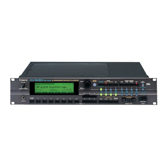
Panel Descriptions Front Panel fig.0-001 VOLUME Knob (PHRASE PREVIEW) This adjusts the volume from the A (MIX) OUTPUT jacks and PHONES jacks. The volume from the OUTPUT B, C and D jacks cannot be adjusted. You can press the knob to listen to the XV-5080 without using any external devices. -
Page 13: Memory Card Slot
E (MODE) [PERFORM] (Performance) Pressed to get into Performance mode. (p. 17) Press this button while holding down [SHIFT] to switch to Part Play mode, enabling you to make changes to the settings for the Patch and Rhythm Set assigned to each Part. (p. 167) [PATCH] Pressed to get into Patch mode. -
Page 14: Rear Panel
232C-type devices, parallel-type devices, etc.) even though they have similar-looking connectors. Use only a specially designed R-BUS (RMDB2) cable to make connections. RMDB II, RMDB 2, and R-BUS refer to the same Roland standard. WORD CLOCK IN Connector (44.1/48 kHz) This is a connector for input of the word clock used for synchronizing external digital devices (BNC type). - Page 15 S/P DIF OUT Connector The XV-5080 features both optical and coaxial digital out connectors (conforming to S/P DIF). S/P DIF: This is a digital interface format used for consumer digital audio devices. * About the Optical Connector Protecting Cap • If you remove the protecting cap, be sure to keep in a safe place to prevent loss.
-
Page 16: Chapter 1 Selecting And Playing A Sound
Chapter 1 Selecting and Playing a Sound Auditioning Sounds on the XV-5080 (Phrase Preview) The Phrase Preview feature allows you to audition Patches on the XV-5080 even when it’s not connected to a MIDI keyboard or sequencer. You can preview a Patch using a Phrase that’s appropriate to the Patch’s type or category. -
Page 17: Playing A Patch On The Xv-5080 From External Midi Devices (Midi Keyboard)
Playing a Patch on the XV- 5080 from External MIDI Devices (MIDI Keyboard) The XV-5080 produces sound in response to MIDI messages that it receives from an external MIDI device such as a MIDI keyboard or sequencer. In order for this to occur, the MIDI transmission channels of the external device must match the MIDI reception channels of the XV-5080. -
Page 18: Selecting Sound Libraries
Chapter 1 Selecting and Playing a Sound sound generators are capable of reliably playing back music files that carry either the General MIDI or General MIDI 2 logo. In some cases, the conventional form of General MIDI, which does not include the new enhancements, is referred to as “General MIDI 1”... -
Page 19: Selecting A Patch
Selecting a Patch Basic Procedure for Selecting a Patch Turn the VALUE dial or press [INC]/[DEC] to select the desired Patch. VALUE Dial To move quickly through the available Patches: Turn the VALUE dial while pressing it or, if you prefer, turn the VALUE dial while pressing [SHIFT]. - Page 20 Chapter 1 Selecting and Playing a Sound The following categories can be selected. Category Group Category Contents — NO ASSIGN No assign Piano AC.PIANO Acoustic Piano EL.PIANO Electric Piano Keys&Organ KEYBOARDS Other Keyboards (Clav, Harpsichord etc.) BELL Bell, Bell Pad MALLET Mallet ORGAN...
-
Page 21: Selecting Patches And Rhythm Sets From An External Midi Device
Selecting Patches and Rhythm Sets from an External MIDI Device By receiving MIDI messages, the XV-5080 can switch Patches (including the Patches for each Part of a Performance) or Rhythm Sets. In Patch or Rhythm Set modes 1. Press [PATCH] — or [RHYTHM] if you wish to select a Rhythm Set —... -
Page 22: Rhythm Sets
Chapter 1 Selecting and Playing a Sound Rhythm Sets Rhythm Set Rhythm Set Bank Select Group Number Number USER 1, 2, 3, 4 PR-A 001, 002 PR-B 001, 002 PR-C 001, 002 PR-D 001, 002 PR-E 001, 002 PR-F 001, 002 PR-G 001, 002 CD-A... -
Page 23: Setting A Patch's Pitch In Octave Steps (Octave Shift)
212), modify the third byte to the appropriate value when transmitting the above exclusive message. Setting a Patch’s Pitch in Octave Steps (Octave Shift) In Patch mode, you can easily change the pitch of an entire Patch. Each time you press [ ], the pitch will change in one- octave steps. -
Page 24: Chapter 2 Using The Xv-5080 Effects
Chapter 2 Using the XV-5080 Effects The XV-5080 contains four independent effects units. Multi-effects The Multi-effects offers 90 different effects. In addition to effects consisting of only one effect, such as distortion and delay, the 90 types also include a number of compound effects, which are formed by combining a number of effects. -
Page 25: Routing Tones To Effects
The screen appears as shown below, according to the settings values. • For MFX fig.02-004.e_70 • For A–D fig.02-005.e_70 • For 1–8 fig.02-006.e_70 The following shows the basic setting procedure. 1. Select the Patch you wish to work with. 2. Press [F6 (Effects)]. The Patch Effect page appears. -
Page 26: Making Multi-Effects Settings
Chapter 2 Using the XV-5080 Effects Dry Send Level Range: 0–127 This sets the level of the signal sent to the output destination set with Output Assign. Chorus Send Level 0–127 Sets how much of the Tone is sent to the Chorus. Reverb Send Level 0–127 Sets how much of the Tone is sent to the Reverb. - Page 27 REV: The Chorus output is sent only to the Reverb. fig.02-010.e Chorus Input Chorus Reverb M+R: The Chorus output is sent to the OUTPUT jacks and to the Reverb. fig.02-011.e Chorus Input Chorus Reverb Input Reverb Chorus Level 0–127 Determines the Chorus output level. Chorus Output Assign A–D Selects the pair of OUTPUT jacks to which the Chorus unit’s stereo output is routed when Chorus Output Select is set to...
-
Page 28: Making Reverb Settings
Chapter 2 Using the XV-5080 Effects Making Reverb Settings These settings allow you to select the desired type of Reverb, its characteristics, and the pair of OUTPUT jacks to which the Reverb unit’s stereo output is routed. On the Effects General page, set the following parameters. Reverb Type Selects the type of Reverb. - Page 29 LF Damp Gain -36–0 dB Adjusts the amount of damping applied to the frequency range selected with LF Damp. With a setting of “0,” there will be no reduction of the reverb’s low-frequency content. HF Damp Freq (LF Damp Frequency) *3 Specifies the frequency above which the high-frequency content of the reverb sound will be reduced, or “damped.”...
-
Page 30: Performance Mode Settings
Chapter 2 Using the XV-5080 Effects Performance Mode Settings Three different Multi-effects can be used in a Performance. Select which of these three Multi-effects to use with Part Output MFX Select. With this parameter, the same Multi- effects are applied to all selected Parts. You can adjust the amount of effect to be applied to the Parts by adjusting their Send Levels to each of the effect units. -
Page 31: Routing Part Outputs
A “*” symbol will appear at the left of the Performance name, indicating that its settings have been modified. fig.02-018.e_70 * If you turn off the power or select another Performance while the “*” symbol is displayed, your new Performance settings will be lost. -
Page 32: Making Chorus Settings
Chapter 2 Using the XV-5080 Effects * When you press [F2 (MFX)] once again, the MFX Param page will reappear. MFXA–C Control 1–4 Source Select the Control Source to be used for changing the Multi- effects parameters, and set the Sens and parameters to be changed by that Control Source. - Page 33 Pressing [F4 (Chorus)] in the General page calls up the Chorus page, in which you can make the following settings. • For Type: 1 (CHORUS) Rate (Chorus Rate) 0.05–10.00 Hz Adjusts the modulation speed of the chorus effect. Depth (Chorus Depth) 0–127 Adjusts the modulation depth of the chorus effect.
-
Page 34: Making Reverb Settings
Chapter 2 Using the XV-5080 Effects Making Reverb Settings These settings allow you to select the desired type of Reverb, its characteristics, and the pair of OUTPUT jacks to which the Reverb unit’s stereo output is routed. On the Effects General page, set the following parameters. Reverb Type Selects the type of Reverb. - Page 35 • For Type: 2 (SRV ROOM)/3 (SRV HALL)/4 (SRV PLATE) Pre Delay (Pre Delay Time) 0.0–100 ms Adjusts the time delay from when the direct sound begins until the reverb sound is heard. Time (Reverb Time) 0–127 Adjusts the time length of reverberation. Size 1–8 Adjusts the size of the simulated room or hall.
-
Page 36: Rhythm Set Mode Settings
Chapter 2 Using the XV-5080 Effects Rhythm Set Mode Settings You can apply Multi-effects, Chorus or Reverb to each of a Rhythm Set’s Tones. You can control the amount of effect to be applied to each Rhythm Tone by adjusting its send level to the Multi-effects, Chorus and Reverb. -
Page 37: Routing Tones To Effects
Routing Tones to Effects This sets the output destination and level for the currently selected Tone, as well as its send level with respect to the Chorus and Reverb. On the Effects General page, set the following parameters. Rhythm Tone Output Assign MFX: The Tone is sent into the Multi-effects. -
Page 38: Making Chorus Settings
Chapter 2 Using the XV-5080 Effects Making Chorus Settings The XV-5080’s Chorus effect unit can also be used as a stereo delay unit. These settings allow you to select chorus or delay, the characteristics of the selected effect type, and the Chorus output routing. -
Page 39: Making Reverb Settings
• For Type: 2 (DELAY) Center (Delay Center) 200–1000 ms, Note Sets the delay time for the delay located at the center of the stereo field. Left (Delay Left) 200–1000 ms, Note Sets the delay time for the delay located at the left side of the stereo field. - Page 40 Chapter 2 Using the XV-5080 Effects • For Type: 1 (REVERB) Type (Reverb/Delay Type) Selects a type of reverb or delay. ROOM1: This is a short reverb with high density. ROOM2: This is a short reverb with low density. STAGE1: This is a reverb with greater late reverberation. STAGE2: This is a reverb with strong early reflections.
-
Page 41: Settings In General Midi Mode
Settings in General MIDI Mode Please refer to Making Effects Settings ([F5 (Effects)]) (p. 227). Chapter 2 Using the XV-5080 Effects Parameters for Each Multi- Effects The multi-effects feature 90 different kinds of effects. Some of the effects consist of two or more different effects connected in series or in parallel. - Page 42 Chapter 2 Using the XV-5080 Effects CHORUS -> FLANGER(p. 63) CHORUS/DELAY(p. 64) FLANGER/DELAY(p. 64) CHORUS/FLANGER(p. 64) STEREO PHASER(p. 65) KEYSYNC FLANGER(p. 65) FORMANT FILTER(p. 66) RING MODULATOR(p. 67) MULTI TAP DELAY(p. 68) REVERSE DELAY(p. 69) SHUFFLE DELAY(p. 70) 3D DELAY (p.
- Page 43 KEYBOARD MULTI RHODES MULTI JD MULTI LoFi (Effects that intentionally degrades the sound quality) LOFI COMPRESS LOFI NOISE STEREO LOFI COMPRESS STEREO LOFI NOISE Guitar and Bass (Effects useful for the Guitar and Bass) OVERDRIVE DISTORTION OVERDRIVE -> CHORUS OVERDRIVE -> FLANGER OVERDRIVE ->...
-
Page 44: Amp Simulator
Chapter 2 Using the XV-5080 Effects 1: STEREO EQ (Stereo Equalizer) This is a four-band stereo equalizer (low, mid x 2, high). fig.2-04 L in 4-Band EQ R in 4-Band EQ Freq/Gain LowFreq (Low Frequency) Select the frequency of the low range (200 Hz/400 Hz). LowGain Adjust the gain of the low frequency. - Page 45 3: DISTORTION This effect produces a more intense distortion than Overdrive. fig.2-06 L in 2-Band Distortion Simulator R in Distortion Drive # Adjust the degree of distortion. The volume will change together with the degree of distortion. Amp Simulator Type (Amp Simulator Type) Select the type of guitar amp.
- Page 46 Chapter 2 Using the XV-5080 Effects 5: SPECTRUM Spectrum is a type of filter which modifies the timbre by boosting or cutting the level at specific frequencies. It is similar to an equalizer, but has 8 frequency points fixed at locations most suitable for adding character to the sound.
-
Page 47: Auto Wah
7: AUTO WAH The Auto Wah cyclically controls a filter to create cyclic change in timbre. fig.2-10 L in L out Auto Wah R in R out Auto Wah Filter (Filter Type) Select the type of filter. LPF:The wah effect will be applied over a wide frequency range. - Page 48 Chapter 2 Using the XV-5080 Effects Level (High Frequency Level) Adjust the volume of the high frequency rotor. Output Level (Output Level) # Adjust the output level. 9: COMPRESSOR The Compressor flattens out high levels and boosts low levels, smoothing out unevenness in volume. fig.2-12 L in 2-Band...
- Page 49 11: HEXA-CHORUS Hexa-chorus uses a six-phase chorus (six layers of chorused sound) to give richness and spatial spread to the sound. fig.2-14 L in L out Balance D Balance W Hexa Chorus Balance W R in R out Balance D Hexa Chorus Rate # Adjust the rate of modulation.
- Page 50 Chapter 2 Using the XV-5080 Effects 13: SPACE-D Space-D is a multiple chorus that applies two-phase modulation in stereo. It gives no impression of modulation, but produces a transparent chorus effect. fig.2-16 Balance D L in Balance W Space D Balance W Space D R in...
- Page 51 Output Level (Output Level) Adjust the output level. 15: STEREO FLANGER This is a stereo flanger. (The LFO has the same phase for left and right.) It produces a metallic resonance that rises and falls like a jet airplane taking off or landing. A filter is provided so that you can adjust the timbre of the flanged sound.
- Page 52 Chapter 2 Using the XV-5080 Effects 16: STEP FLANGER The Step Flanger effect is a flanger in which the flanger pitch changes in steps. The speed at which the pitch changes can also be specified in terms of a note-value of a specified tempo.
- Page 53 frequencies of the feedback, set this parameter to BYPASS. Feedback # Adjust the proportion (%) of the delay sound that is fed back into the effect. Negative (-) settings will invert the phase. FBK Mode (Feedback Mode) Select the way in which delay sound is fed back into the effect.
- Page 54 Chapter 2 Using the XV-5080 Effects Modulation Rate # Adjust the speed of the modulation. Depth Adjust the depth of the modulation. Phase Adjust the spatial spread of the sound. EQ Gain Low (Low Gain) Adjust the gain of the low frequency range. High (High Gain) Adjust the gain of the high frequency range.
- Page 55 Balance Balance (Effect Balance) # Adjust the volume balance between the direct sound and the delay sound. With a setting of D100:0W only the direct sound will be output, and with a setting of D0:100W only the delay sound will be output. Output Level (Output Level) Adjust the output level.
-
Page 56: Pitch Shift
Chapter 2 Using the XV-5080 Effects 21: TIME CONTROL DELAY This effect allows you to use a specified controller (the controller selected in EFX Control Source) to control the delay time and pitch in realtime. Lengthening the delay will lower the pitch, and shortening it will raise the pitch. For details refer to “Changing the Multi-Effects Settings From an External MIDI Device (p. - Page 57 Pitch B Coarse (Coarse Pitch B) #2 Adjust the pitch of Pitch Shift B in semitone steps (-2-+1 octaves). Fine (Fine Pitch B) #2 Make fine adjustments to the pitch of Pitch Shift B in 2-cent steps (-100-+100 cents). One cent is 1/100th of a semitone. Pan (Output Pan B) Adjust the stereo location of the Pitch Shift B sound.
- Page 58 Chapter 2 Using the XV-5080 Effects 24: REVERB The Reverb effect adds reverberation to the sound, simulating an acoustic space. fig.2-30 L in Balance D Balance W Reverb Balance W R in Balance D Reverb Type (Reverb Type) Select the type of Reverb effect. ROOM1: dense reverb with short decay ROOM2: sparse reverb with short decay STAGE1: reverb with greater late reverberation...
- Page 59 Output Level (Output Level) # Adjust the output level. 26: OVERDRIVE CHORUS This effect connects an overdrive and a chorus in series. fig.2-32 L in Balance D Overdrive Chorus R in Balance D Overdrive Drive Adjust the degree of overdrive distortion. The volume will change together with the degree of distortion.
- Page 60 Chapter 2 Using the XV-5080 Effects 28: OVERDRIVE DELAY This effect connects an overdrive and a delay in series. fig.2-34 L in Balance D Overdrive Delay Feedback R in Balance D Overdrive Drive Adjust the degree of overdrive distortion. The volume will change together with the degree of distortion.
- Page 61 32: ENHANCER CHORUS This effect connects an enhancer and a chorus in series. fig.2-38 L in Enhancer Balance D Chorus R in Enhancer Balance D Enhancer Sens (Enhancer Sens) # Adjust the sensitivity of the enhancer. Mix Level (Enhancer Mix Level) Adjust the ratio with which the overtones generated by the enhancer are combined with the direct sound.
- Page 62 Chapter 2 Using the XV-5080 Effects 34: ENHANCER DELAY This effect connects an enhancer and a delay in series. fig.2-40 L in Enhancer Balance D Delay Feedback R in Enhancer Balance D Enhancer Sens # Adjust the sensitivity of the enhancer. Mix Level (Enhancer Mix Level) Adjust the ratio with which the overtones generated by the enhancer are combined with the direct sound.
- Page 63 Output Level (Output Level) Adjust the output level. 36: FLANGER DELAY This effect connects a flanger and a delay in series. fig.2-42 Balance D L in Balance D Feedback Balance W Flanger Delay Balance W Feedback R in Balance D Balance D Flanger Pre Delay (Flanger Pre Delay Time)
- Page 64 Chapter 2 Using the XV-5080 Effects Depth (Flanger Depth) Adjust the modulation depth of the flanger effect. Feedback (Flanger Feedback Level) Adjust the proportion (%) of the flanger sound that is fed back into the effect. Negative (-) settings will invert the phase.
-
Page 65: Stereo Phaser
41:STEREO PHASER This is a stereo phaser. With the Step effects, you can also make stepped changes in the pitch of sounds to which the Phaser effect is applied. fig.2-51 2-Band L in Phaser 2-Band Phaser R in Phaser Type (Phaser Type) Selects the type of Phaser. - Page 66 Chapter 2 Using the XV-5080 Effects Depth (LFO Depth) Adjust the modulation depth of the flanger sound. Fbk # Adjust the proportion (%) of the flanger sound that is to be returned to the input. Positive (+) settings will return the signal to the input with the original phase, while negative (-) settings produce an inverted phase.
-
Page 67: Ring Modulator
setting is the vowel 2. Rate Sets the frequency at which the two vowels will be switched. Depth Sets the effect depth. Manual Sets the point at which the two vowels will be switched. When set to 50, Vowels 1 and 2 switched in the same amount of time. -
Page 68: Multi Tap Delay
Chapter 2 Using the XV-5080 Effects Output Level (Output Level) Adjust the output level. 45:MULTI TAP DELAY The Multi Tap Delay has four delays. Each of the Delay Time parameters can be specified as a note length of the selected tempo. -
Page 69: Reverse Delay
Output Level (Output Level) Adjust the output level. 46:REVERSE DELAY Reverse Delay is a delay effect that adds the reverse of the input sound as the delay sound. fig.2-56 L in Feedback Rev. Delay Delay R in Delay 1 (Delay Time 1) Adjust the delay time from the original sound until the delay 1 sound is heard. -
Page 70: Shuffle Delay
Chapter 2 Using the XV-5080 Effects 47:SHUFFLE DELAY Shuffle Delay adds a shuffle to the delay sound, giving the sound a bouncy delay effect with a swing feel. fig.2-57 L in Feedback Delay 1 Delay Delay 2 R in Delay Time (Delay Time) # Adjust the delay time from the original sound until the delay sound is heard. - Page 71 HF Damp Adjust the frequency above which delayed sound fed back to the delay input will be cut. If you do not want to cut the high frequencies of the feedback, set this parameter to BYPASS. Feedback # Adjust the proportion (%) of the delay sound that is to be returned to the input.
-
Page 72: Lofi Compress
Chapter 2 Using the XV-5080 Effects Pan 1:2:3 (Output Pan 1:2:3) Specify the stereo location of the pitch shift 1–3 sound. L64 is far left, 0 is center, and 63R is far right. Output Level (Output Level) Adjust the output level. 50:LOFI COMPRESS This is an effect that intentionally degrades the sound quality. -
Page 73: Speaker Simulator
HPF:The frequency region below the Cutoff Freq setting will be cut. Cutoff (Cutoff Frequency) Adjust the frequency at which the filter will begin cutting. Radio Noise Detune # Simulates the tuning noise of a radio. As this value is raised, the tuning will drift further. - Page 74 Chapter 2 Using the XV-5080 Effects Output Level (Output Level) # Adjust the output level. 53:OVERDRIVE 2 This is an overdrive that provides heavy distortion. fig.2-63 L in 2-Band Overdrive Simulator R in Overdrive Drive # Adjust the amount of distortion. The volume will change together with the degree of distortion.
-
Page 75: Stereo Compressor
55:STEREO COMPRESSOR fig.2-65 L in Compressor 2-Band EQ R in Compressor 2-Band EQ Compressor Attack Adjust the attack time of an input sound. Sustain Adjust the time over which low level sounds are boosted until they reach the specified volume. Post Gain Adjust the output gain. - Page 76 Chapter 2 Using the XV-5080 Effects 57:GATE The Gate effect cuts the reverb’s delay according to the volume of the sound input to the effects device. Use this in situations such as when you want to force a decrease in the decay sound.
- Page 77 Threshold (Reset Threshold) Sets the volume level at which the reset begins. Monitor (Reset Monitor) Determines whether the sound used as the reset trigger is output (ON) or not (OFF). This parameter is disabled when Reset is set to OFF or Source. Beat Change Mode Sets the manner in which the volume changes as one beat...
- Page 78 Chapter 2 Using the XV-5080 Effects Chorus Rate (LFO Rate) # Adjust the modulation frequency of the chorus sound. Depth (LFO Depth) Adjust the modulation depth of the chorus sound. Phase Adjust the spaciousness of the chorus sound. Pre Delay (Pre Delay Time) Adjust the delay time from the original sound until when the chorus sound is heard.
-
Page 79: Auto Pan
Step Rate Switch (Step Rate Switct) Determines whether the pitch is changed in a stepped fashion (ON) or not (OFF). Step Rate (Step Rate) # And adjust the rate at which the pitch will change. EQ Gain Low (Low Gain) Adjust the low frequency gain (amount of boost or cut). - Page 80 Chapter 2 Using the XV-5080 Effects The teeth in SAW1 and SAW2 point at opposite directions. fig.2-73a Saw1 Saw2 Rate # Adjust the frequency (speed) of the change. Depth # Sets the depth to which the effect is applied. EQ Gain Low (Low Gain) Adjust the low frequency gain (amount of boost or cut).
- Page 81 Output Level (Output Level) Adjusts the output level. 65: STEREO AUTO WAH This is a stereo auto wah. fig.02-065m.e L in Auto Wah 2-Band EQ R in Auto Wah 2-Band EQ Auto Wah Filter Type Selects the type of filter. LPF: The wah effect will be applied over a wide frequency range.
- Page 82 Chapter 2 Using the XV-5080 Effects amount of time. Setting this higher than 50 increases the time for Vowel 1; setting this lower than 50 decreases the time for Vowel 1. Phase # Sets the phase shift of the left and right sounds when the two vowels are switched.
- Page 83 68: REVERSE DELAY 2 This allows you to set even longer delay times (max. 1500 ms) for the Multi-Tap Delay function. fig.02-068m.e L in Feedback Rev. Delay Delay R in Delay 1–4 (Delay Time 1–4) Adjusts the delay time from the direct sound until the delay 1 –...
- Page 84 Chapter 2 Using the XV-5080 Effects Feedback # Adjusts the proportion (%) of the delay sound that is fed back into the delay input. Positive (+) settings will return the signal to the input with the original phase, while negative (-) settings produce an inverted phase.
- Page 85 High (High Gain) Adjusts the gain of the high frequency range. Positive (+) settings will emphasize (boost) the high- frequency range. Balance Balance (Effect Balance) # Sets the volume balance between the direct sound and the effect sound. With a setting of D100:0W only the direct sound will be output, and with a setting of D0:100W the effect sound will be output.
- Page 86 Chapter 2 Using the XV-5080 Effects EQ Gain Low (Low Gain) Adjusts the gain of the low frequency range. Positive (+) settings will emphasize (boost) the low- frequency range. High (High Gain) Adjusts the gain of the high frequency range. Positive (+) settings will emphasize (boost) the high- frequency range.
- Page 87 Fast (Low Frequency Fast Rate) Adjusts the speed of the low-range rotor for the fast-speed setting. Accel (Low Frequency Acceleration) Adjusts the time over which the rotation speed of the low- range rotor will change from slow-speed to fast-speed (or fast-speed to slow-speed) rotation.
-
Page 88: Pitch Shifter
Chapter 2 Using the XV-5080 Effects EQ Gain Low (EQ Low Gain) Adjusts the low-range gain of the equalizer. Mid (EQ Mid Gain) Adjusts the gain of the area specified by the EQ M Fq parameter and the EQ M Q parameter. High (EQ High Gain) Adjusts the high-range gain of the equalizer. - Page 89 74: RHODES MULTI Rhodes Multi provides Enhancer (EH), Phaser (PH), Chorus or Flanger (CF), and Tremolo or Pan (TP) effects connected in series. fig.02-074m.e L in Enhancer Resonance Phaser R in Enhancer Chorus/ Flanger Feedback Chorus/ Flanger Sequence Enhancer (Enhancer Switch) Turns the Enhancer on/off.
- Page 90 Chapter 2 Using the XV-5080 Effects Tremolo/Pan Type Selects either Tremolo or Pan. ModWave (Modulation Wave) Selects the way in which tremolo or pan will be modulated. Tri: The sound will be modulated like a triangle wave. Sqr: The sound will be modulated like a square wave.
- Page 91 modified. 250Hz (250Hz Gain) Specifies the gain (amount of boost or cut) at 250 Hz. 500Hz (500Hz Gain) Specifies the gain (amount of boost or cut) at 500 Hz. 1000Hz (1000Hz Gain) Specifies the gain (amount of boost or cut) at 1000 Hz. 2000Hz (2000Hz Gain) Specifies the gain (amount of boost or cut) at 2000 Hz.
- Page 92 Chapter 2 Using the XV-5080 Effects 77: STEREO LO-FI NOISE This is a stereo Lo-Fi noise. In addition to a Lo-Fi effect, this effect also generates various types of noise such as radio noise and disc noise. fig.02-077m.e L in Lo-Fi Radio Noise Gen.
-
Page 93: Amp Level
Output Level (Output Level) Adjusts the output level. 78: GUITAR AMP SIMULATOR This is an effect that simulates an amp. fig.02-078m.e L in Pre Amp Speaker R in Amp Simulator Switch (Pre Amp Switch) Turns the amp switch on/off. Type (Pre Amp Type) Selects the type of guitar amp. - Page 94 Chapter 2 Using the XV-5080 Effects 79: STEREO OVERDRIVE This is a stereo overdrive. fig.02-079m.e Overdrive L in Simulator R in Overdrive Simulator Overdrive Drive # Adjusts the degree of distortion. The volume will change together with the degree of distortion. Tone Specifies the sound quality of the Overdrive effect.
- Page 95 81: GUITAR MULTI A Guitar Multi 1 connects Compressor (Cmp), Overdrive or Distortion (ODDS), Amp Simulator (Amp), Delay (Dly), and Chorus or Flanger (CF) effects in series. L in Overdrive/ Compressor Distortion R in Chorus/ Delay Flanger Feedback Delay Delay Chorus/ Flanger Feedback...
- Page 96 Chapter 2 Using the XV-5080 Effects Amp Simulator Amp Type (Amp Simulator Type) Selects the type of guitar amp. Small: small amp BltIn: built-in type amp 2-Stk: large double stack amp 3-Stk: large triple stack amp Delay Left Time (Delay Time Left) Adjust the delay time from the original sound until the left delay sound is heard.
- Page 97 Amp Sim (Amp Simulator Switch) Turns the Amp Simulator on/off. 3 Band EQ (3 Band EQ Switch) Turns the equalizer on/off. Cho/Flg (Chorus/Flanger Switch) Turns the chorus/flanger on/off. Compressor Attack (Compressor Attack) Specifies the duration of the attack when sound is input. Sustain (Compressor Sustain) Specifies the time over which low-level sounds will be boosted to reach the specified volume.
- Page 98 Chapter 2 Using the XV-5080 Effects Cutoff (Cutoff Frequency) Sets the cutoff frequency when a specific frequency band is cut off by a filter. Output Level (Output Level) Adjusts the output level. Pan (Output Pan) Adjusts the stereo location of the output sound. 83: GUITAR MULTI C Guitar Multi C connects Overdrive or Distortion (ODDS), Wah (Wah), Amp Simulator (Amp), Delay (Dly), and Chorus...
- Page 99 Feedback (Delay Feedback Level) Adjusts the proportion (%) of the delay sound that is fed back into the delay input. HF Damp Adjusts the frequency above which sound fed back to the effect will be cut. If you do not want to damp the high frequencies, set this parameter to BYPASS.
- Page 100 Chapter 2 Using the XV-5080 Effects EQ Gain Low (EQ Low Gain) Adjusts the low-range gain of the equalizer. EQ M Gain (EQ Mid Gain) Adjusts the gain of the area specified by the EQ M Fq parameter and the EQ M Q parameter. High (EQ High Gain) Adjusts the high-range gain of the equalizer.
- Page 101 85: CLEAN GUITAR MULTI B Clean Guitar Multi 2 provides Auto-wah (AW), Equalizer (EQ), Delay (Dly), and Chorus or Flanger (CF) effects connected in series. fig.02-085m.e L in 3-Band EQ R in Chorus/ Delay Flanger Seqeuence Wah (Auto Wah Switch) Turns the Auto Wah on/off.
- Page 102 Chapter 2 Using the XV-5080 Effects Chorus/Flanger Type Selects either Chorus or Flanger. Rate Sets the modulation speed for the chorus or flanger. Depth Sets the modulation depth for the chorus or flanger. Feedback (CF Feedback) Adjusts the proportion (%) of the flanger sound that is fed back into the effect.
- Page 103 together with the degree of distortion. Level (Overdrive/Distortion Level) # Sets the volume of the Overdrive/Distortion sound. Amp Simulator Type (Amp Simulator Type) Selects the type of bass amp. Small: small amp BltIn: built-in type amp 2-Stk: large double stack amp 3 Band EQ Low (EQ Low Gain) Adjusts the low-range gain of the equalizer.
- Page 104 Chapter 2 Using the XV-5080 Effects 87: ISOLATOR 2 This adds a filter to the ISOLATOR effect. Isolator is an equalizer which cuts the volume greatly, allowing you to add a special effect to the sound by cutting the volume in varying ranges.
- Page 105 500Hz (500Hz Gain) Specifies the gain (amount of boost or cut) at 500 Hz. 1000Hz (1000Hz Gain) Specifies the gain (amount of boost or cut) at 1000 Hz. 1250 Hz (1250 Hz Gain) Specifies the gain (amount of boost or cut) at 1250 Hz. 2000 Hz (2000 Hz Gain) Specifies the gain (amount of boost or cut) at 2000 Hz.
-
Page 106: Copying Effect Settings
Chapter 2 Using the XV-5080 Effects When Using 3D Effects The following 3D effects utilize RSS (Roland Sound Space) technology to create a spaciousness that cannot be produced by delay, reverb, chorus, etc. 48: 3D DELAY 60: 3D CHORUS 61: 3D FLANGER... -
Page 107: Chapter 3 Selecting Output Jacks
Chapter 3 Selecting Output Jacks The XV-5080 has four sets of stereo outputs. These outputs allow you to separate sounds—or groups of sounds—from the XV-5080’s overall stereo mix, and to send them to their own external destinations. For example, you could route a stereo Rhythm Set to a pair of output jacks connected to an external effects device. -
Page 108: Parameters
Chapter 3 Selecting Output Jacks Parameters The parameters related to Patch output settings are shown below. PATCH Effects General page ([PATCH] - [F6 (Effects)] - [F1 (General)]) This sets the output destination and level for the currently selected Tone, as well as its send level with respect to the Chorus and Reverb. - Page 109 PATCH Common General #1 page ([PATCH] - [F1 (COMMON)] - [F1 (General)]) Common Level (Patch Level) Range: 0–127 Sets the volume of the Patch. * You can specify the level for each Tone using the Tone Level parameter (TVA; p. 143). Pan (Patch Pan) Range: L64–63R Sets the stereo position of the Patch.
-
Page 110: Example Of Settings
Chapter 3 Selecting Output Jacks Example of Settings Assigning Different Output Destinations for the Tones in a Patch In this example, let’s suppose we have a Patch composed of four Tones, and we are outputting Tone 1 from the A OUTPUT jacks, Tone 2 from the B OUTPUT jacks, Tone 3 from the INDIVIDUAL 5 jack, and Tone 4 from the INDIVIDUAL 6 jack. -
Page 111: Performance Mode Settings
Performance Mode Settings Signal (PART) Flow fig.03-002.e Output Assign PART Parameters The parameters related to Part output settings are shown below. PERFORMANCE Effects General page ([PERFORM] - [F6 (Effects)] - [F1 (General)]) Sets the output destination and level for the selected Part, as well as its send level with respect to the Chorus and Reverb. - Page 112 Chapter 3 Selecting Output Jacks Part Chorus Send Level Range: 0–127 Sets how much of the Part is sent to the Chorus. Its final output destination is determined by the Chorus output setting. Part Reverb Send Level Range: 0–127 Sets how much of the Part is sent to the Reverb. Its final output destination is determined by the Reverb output setting.
-
Page 113: Example Of Settings
SYSTEM General #1 page ([SYSTEM] - [F1 (General)]) Master Level (Master Level) Range: 0–127 Adjusts the volume of the entire XV-5080. Example of Settings Selecting Different Output Destinations for Parts in a Performance This example describes the procedure for outputting Part 1 from the A (MIX) OUTPUT jacks without sending it through any internal effects, sending Part 2 through the Multi-effects A and then outputting it from the B OUTPUT jack, and... -
Page 114: Rhythm Set Mode Settings
Chapter 3 Selecting Output Jacks Rhythm Set Mode Settings Signal (RHYTHM TONE) Flow fig.03-003.e Output Assign RHYTHM TONE Parameters The parameters related to Patch output settings are shown below. RHYTHM Effects General page ([RHYTHM] - [F6 (Effects)] - [F1 (General)]) These parameters set the output destination and level for the currently selected Rhythm Set Tone, and allow you to set its send levels to the Chorus and Reverb. - Page 115 MFX Chorus Send Level Range: 0–127 Determines the level of the post-Multi-effects processor signal sent to Chorus. Its final output destination is determined by the Chorus output setting. MFX Reverb Send Level Range: 0–127 Determines the level of the post-Multi-effects processor signal sent to Reverb.
- Page 116 Chapter 3 Selecting Output Jacks SYSTEM Output page ([SYSTEM] - [F2 (OutP&EQ)]) Output Mix/Parallel Mode Available Settings: MIX: Signals that are set to be output from jacks other than the A (MIX) OUTPUT jacks are mixed and output from the A (MIX) OUTPUT jacks.
-
Page 117: Settings In General Midi Mode
Settings in General MIDI Mode Signal (PART) Flow fig.03-004.e Output Assign Part Rev (GM CHORUS) Parameters The parameters related to Part output settings are shown below. GM Effects General page ([GM] - [F6 (Effects)] - [F1 (General)]) Sets the output destination and level for the selected Part, as well as its send level with respect to the Chorus and Reverb. - Page 118 Chapter 3 Selecting Output Jacks Reverb Send Level Range: 0–127 Sets the amount of the Chorus unit’s output to be sent to the Reverb. Its final output destination is determined by the Reverb output setting. Reverb Output Assign Range: A–D Selects the OUTPUT jacks to which the Reverb unit’s stereo output is routed.
-
Page 119: Digital Connections Using R-Bus
Digital Connections Using R- The XV-5080 comes equipped with an R-BUS connector. This connector allows you to make an eight-channel digital connection using a single R-BUS cable (RBC-1/RBC-5; optional). In addition, you can connect the R-BUS connector to a DIF-AT, AE-7000, or other such digital device, making it possible for you to convert to different digital formats. -
Page 120: Eight-Channel R-Bus Digital Connection
Chapter 3 Selecting Output Jacks Eight-Channel R-BUS Digital Connection fig.RBUS-1.e XV-5080 ——–> Device Equipped with R-BUS Connector (One Example) When Making the XV-5080 the Word Clock Master • XV-5080 Settings Master Clock: INTERNAL Master Freq: 44.1 or 48.0 kHz (set to match the sampling rate of the connected device) •... -
Page 121: Converting To The Various Digital Formats
Converting to the Various Digital Formats Digital Output to an ADAT Connect a DIF-AT, and you’ll then be able to output to an ADAT. When Making the XV-5080 the Word Clock Master fig.RBUS-2.e XV-5080 Settings • XV-5080 Settings Master Clock: INTERNAL Master Freq: 44.1 or 48.0 kHz (set to match the sampling rate of the connected device) DIF-AT Clk Select:R-BUS •... -
Page 122: Digital Output To A Tascam Da Series
Chapter 3 Selecting Output Jacks Digital Output to a TASCAM DA Series Connecting a DIF-AT then allows you to output to a TASCAM DA Series device. fig.RBUS-3.e When Making the XV-5080 the Word Clock Master Settings You cannot make these settings (the DIF-AT cannot be used as Word Clock Slave with TASCAM devices). When Making the XV-5080 the Word Clock Slave Settings •... -
Page 123: Digital Output To An Aes/Ebu Device
Digital Output to an AES/EBU Device Connecting an AE-7000 then allows you to output to an AES/EBU device. When Making the XV-5080 the Word Clock Slave Settings fig.RBUS-4.e XV-5080 Word Clock • XV-5080 Settings Master Clock: R-BUS • AE-7000 Settings CLOCK SOURCE SELECT:WORD CLOCK or INPUT A (for detailed instructions, refer to the AE-7000 manual) When Making the XV-5080 the Word Clock Master Settings... -
Page 124: Synchronizing The Xv-5080 To The Word Clock Arriving At Word Clock In
Chapter 3 Selecting Output Jacks Synchronizing the XV-5080 to the Word Clock arriving at WORD CLOCK IN fig.RBUS-6.e Settings • XV-5080 Settings Master Clock: WORD CLOCK IN • Word Clock Master Device Settings Set the sampling rate for the device acting as Word Clock Master to 44.1 or 48.0 kHz. * Word Clock signals input at WORD CLOCK IN are output through R-BUS and S/P DIF. -
Page 125: Chapter 4 Creating Patches
Chapter 4 Creating Patches Types of Patches and Their Composition The basic unit of sound used in performances on the XV-5080 is called a Patch; there are two types of Patches, Four-Tone Patches and Multi-Partial Patches. The Patch type is determined by the Tone type setting, in the Patch Common screen (p. -
Page 126: Multi-Partial Patch
Chapter 4 Creating Patches Multi-partial Patch Patches using data loaded into the XV-5080 from sampler Multi-Partial Patch Sample 1 Sample 2 Sample 3 Sample 4 libraries are of this type. Multi-Partial Patches are created by assigning the constituent sounds, called Partials, to the keys on the keyboard, with up to 88 Partials being assignable. -
Page 127: Settings Common To The Entire Patch
Settings Common to the Entire Patch Setting Procedure: 1. Select the Patch you’re going to use. 2. Press [F1 (COMMON)]. 3. Use [F1]–[F5] to select the page containing the parameter you wish to set. * When the setting pages are displayed, you can press TONE SWITCH [1]–[4] to turn each Tone on/off. -
Page 128: Octave Shift
Chapter 4 Creating Patches INDIV 1–8: The Patch is sent to the selected INDIVIDUAL 1– 8 jack. (Mono output) TONE/KEY: The output routing is determined by the settings of each Tone/Partial. Octave&Tune (Patch Octave & Tune) Octave Shift Range: -3– +3 Sets the pitch of the Patch in units of an octave (+/-3 octaves). -
Page 129: Control (Patch Control)
Release Offset Range: -63– +63 This simultaneously lowers or raises the individual TVA ENVELOPE T4 values of the Tones/Partials in the Patch. With Multi-Partial Patches, only TVA changes. Velo Sens Offset (Velocity Sensitivity Offset) Range: -63– +63 Sets the relative ratio of change of the TVF VELOCITY V- Cutoff and TVA V-Sens values set in each of the Tones/ Partials comprising the Patch. - Page 130 Chapter 4 Creating Patches that uses multiple tones, it may stop being heard in MONO. When making large pitch changes, set the Legato Retrigger to “ON.” Bender Sets the bend range. Bend Range Up Range: 0–48 Specifies the amount (in semitones) of pitch bend that will occur when the bender lever of a connected MIDI keyboard is moved to the far right position (or for a wheel, the fully upward position).
-
Page 131: Structure (Patch Structure)
Structure (Patch Structure) These parameters can be set only for Four-Tone Patches. PATCH Common Structure page ([PATCH] - [F3 (Struct)]) fig.04-011.e_70 Tone 1&2/Tone 3&4 Determines how Tone 1 and 2, or Tone 3 and 4 are connected. Type (Structure Type) Range: 1–10 fig.04-012.e TYPE 1... -
Page 132: K. Range (Patch Key Range)
Chapter 4 Creating Patches other Tone to be connected in the simple order of WG/TVF/ TVA. Booster (Booster Gain) Range: 0/+6/+12/+18 If the “Type” parameter has been set to 3 or 4, you can set the Booster strength. The Booster amplifies the incoming signal, causing it to distort. -
Page 133: V. Range (Patch Velocity Range)
U.F (TMT Keyboard Fade Width Upper) Range: 0–127 Determines what will happen to the Tone’s level when a note that’s higher than the Tone’s specified keyboard range is played. Higher settings result in a more gradual change in volume. If you don’t want the Tone to sound at all when a note above the keyboard range is played, set this parameter to 0. -
Page 134: Creating Four-Tone Patches
Chapter 4 Creating Patches U.F (TMT Velocity Fade Width Upper) Range: 0–127 This determines what will happen to the Tone’s level when the Tone is played at a velocity greater than its specified velocity range. Higher settings result in a more gradual change in volume. -
Page 135: Tips For Selecting A Waveform
fig.04-027.e 5. Press [ ] to move the cursor to the parameter you want to set. 6. Turn the VALUE dial or press [INC]/[DEC] to select the desired value. * If you make a mistake when setting a parameter’s value, or you don’t like the change you have made, just press [UNDO] to restore the original value of the parameter. -
Page 136: Modifying The Waveform And Pitch ([F2] (Wg))
Chapter 4 Creating Patches The following diagram shows an example of a sound – an electric organ – that combines one-shot and looped waveforms. fig.04-030.e TVA ENV for looped Organ TVA ENV for one-shot Key- waveform (sustain portion) click waveform (attack portion) Key-off Notes for Editing One-Shot Waveforms You cannot give a one-shot waveform a longer decay —... - Page 137 Gain (Wave Gain) Range: -6/0/+6/+12 Specifies the gain (amplitude) of the waveform. The value changes in 6 dB (decibel) steps—an increase of 6 dB doubles the waveform’s gain. If you intend to use the Booster to distort the waveform’s sound, set this parameter to its maximum value.
- Page 138 Chapter 4 Creating Patches Time (Tone Delay Time) Range: 0–127/Note Specifies the time after which the Tone will sound when using Tone Delay. When the Type parameter (STRUCT page) has a setting of 2– 10, the outputs of Tones 1 (3) and 2 (4) will be combined with Tone 2 (4).
- Page 139 Depth (Pitch Envelope Depth) Range: -12– +12 Determines the amount of pitch enveloping to be used. Higher values will cause greater change. Negative (-) settings invert the direction of the changes made by the Pitch Envelope. Time Keyfollow (Pitch Envelope Time Keyfollow) Range: -100–...
-
Page 140: Using The Filter To Modify The Brightness ([F3 (Tvf)])
Chapter 4 Creating Patches point, then go back and forth between the Loop Start point and the Loop End point. REV-ONE (Reverse One-shot) The sample will be played back only once from the Loop End point to the Start point in the reverse direction. REV (Reverse): When the sample has been played back from the Loop End point to the Start point, it will be repeatedly played back in... - Page 141 filter reduces the frequencies more gently than LPF2. This can be very effective with acoustic-instrument-based Tones, since nothing is done to weaken the power and energy of the sound. * This disables the Resonance setting. Cutoff Freq (TVF Cutoff Frequency) Range: 0–127 Specifies the frequency (cutoff frequency) at which the filter will begin to affect the frequency characteristics of the...
- Page 142 Chapter 4 Creating Patches PATCH TVF Envelope page ([PATCH] - [F3 (TVF)] - [F2 (TVF Env)]) fig.04-044.e_70 TVF Envelope These parameters determine the amount of filter enveloping – changes to your original cutoff frequency setting that occur over time – the effect of velocity on the TVF envelope, and the basic characteristics of the TVF envelope itself.
-
Page 143: Changing The Volume And Stereo Location ([F4 (Tva)])
Changing the Volume and Stereo Location ([F4 (TVA)]) The TVA (Time Variant Amplifier) controls volume changes to the Tone as well as its stereo positioning. PATCH TVA Parameter page ([PATCH] - [F4 (TVA)] - [F1 (TVA Prm)]) fig.04-046.e_70 Level (Tone Level) Range: 0–127 Sets the volume of the Tone. - Page 144 Chapter 4 Creating Patches Keyfollow (Tone Pan Keyfollow) Range: -100– +100 Use this parameter when you want each note’s keyboard position to affect its stereo location. Higher values for this parameter will cause more extreme changes to the T2–T4 settings as you play further away from Middle C (C4) – at Middle C itself, your original T2–T4 settings are in effect.
-
Page 145: Applying Vibrato Or Tremolo ([F5 (Lfo&Ctl)])
Applying Vibrato or Tremolo ([F5 (LFO&CTL)]) The LFO (Low Frequency Oscillator) can alter various Tone settings in a back-and-forth, cyclic manner. Each Tone has two LFOs, and each can apply the desired amount of repetitive change to the Tone’s Pitch, TVF cutoff frequency, TVA Level and TVA Pan settings. - Page 146 Chapter 4 Creating Patches Fade (LFO Fade) Mode (LFO Fade Mode) Sets how the LFO will be applied. Available Settings: ON-IN: The LFO will fade in after the key is pressed. fig.04-051.e Delay Fade high (more) Time Time WG Pitch / TVF Cutoff Frequency / TVA Level / TVA Pan key is...
- Page 147 PITCH ENV: Pitch envelope TVF ENV: TVF envelope TVA ENV: TVA envelope Destination Selects the parameters to be controlled. (p. 218) Sens (Sensitivity) Range: -63– +63 Adjusts the amount of change that will occur in response to controller changes. Negative (-) values invert the change. Negative (-) settings will invert the phase.
-
Page 148: Creating Multi-Partial Patches
Chapter 4 Creating Patches Creating Multi-Partial Patches When creating and playing Multi-Partial Patches, you must have a separate device to load samples from a sampler library or other source to the XV-5080. First, load a Patch or Performance from the sound library (such as the optional L-CDX Series). -
Page 149: Editing Partials
Assign (Assign Type) Selects the range over which the Split settings are applied. MULTI: The settings affect all Partials. SINGLE: The settings affect a single selected Partial. MIDI (MIDI Switch) Range: OFF/SELECT/SET Determines whether or not selections and settings are be made with a MIDI keyboard. -
Page 150: Editing Samples
Chapter 4 Creating Patches Editing Samples PATCH WG SMT#1 page ([PATCH] - [F2 (WG)] - [F2 (SMT)]) fig.04-061.e_70 SMT (Sample Mix Table) The SMT number is displayed. No. (Sample Number) Specify the number of the Sample to be assigned. Name (Sample Name) The name of the assigned sample will be displayed. - Page 151 PATCH WG SMT#2 page ([PATCH] - [F2 (WG)] - [F2 (SMT)]) fig.04-063.e_70 SMT Velocity Control (SMT Velocity Control Switch) Range: OFF/ON Determines whether Velocity messages from a MIDI keyboard or sequencer will be recognized (ON), or ignored (OFF). L.F (SMT Velocity Fade Width Lower) Range: 0–125 Determines the extent over which the sound level is faded after SMT Velocity Range Upper.
-
Page 152: Using The Filter To Modify The Brightness ([F3 (Tvf)])
Chapter 4 Creating Patches ONE SHOT: The sample will be played back only once, from the Start point to the Loop End point. Loop Start Start P. ALT (Alternate): When the sample has been played back from the Start point to the Loop End point, playback will repeat to the Loop Start point, then go back and forth between the Loop Start point and the Loop End point. - Page 153 keyboard to select the pertial. PATCH TVF Parameter page ([PATCH] - [F3 (TVF)] - [F1 (TVF Prm)]) fig.04-066.e_70 Filter Type (TVF Filter Type) Selects the filter type. A filter typically reduces, or attenuates, a specific frequency range within a Tone in order to accentuate its other frequencies.
- Page 154 Chapter 4 Creating Patches PATCH TVF Envelope page ([PATCH] - [F3 (TVF)] - [F2 (TVF Env)]) These parameters determine the amount of filter enveloping – changes to your original cutoff frequency setting that occur over time – the effect of velocity on the TVF envelope, and the basic characteristics of the TVF envelope itself.
-
Page 155: Making The Volume Change ([F4 (Tva)])
Making the Volume Change ([F4 (TVA)]) Press [F5 (Global)] to turn Global on and display the " " to the left of the function name; the same settings are applied to all Partials used in the Patch being edited. When Global is set to OFF, then only the currently selected Partial (the Partial appearing on the screen) is edited. -
Page 156: Applying Vibrato Or Tremolo ([F5 (Lfo&Ctl)])
Chapter 4 Creating Patches Level (TVA Envelope Level 1–3) Range: 0–127 Each TVA envelope level value determines an amount of change to be applied to the original Tone level setting. Velocity Sens (TVA Envelope Velocity Sensitivity) Time1 (TVA Envelope Time 1 Velocity Sensitivity) Range: -63–... - Page 157 Rate (LFO Rate) Range: 0–127 Adjusts the basic modulation rate, or speed, of the LFO. Detune (LFO Rate Detune) Range: 0–127 Changes the rate of the LFO. Delay (LFO Delay) Time (LFO Delay Time) Range: 0–127 This sets the time interval between the moment when a key is pressed (or released) and the moment the LFO begins to take effect.
-
Page 158: Making Effect Settings
Chapter 4 Creating Patches Destination Selects the parameters to be controlled. (p. 218) Sens (Sensitivity) Range: -63– +63 Adjusts the amount of change that will occur in response to controller changes. Negative (-) values invert the change. Negative (-) settings will invert the phase. For LFO rates, negative (-) values slow down the LFO, and positive (+) values will speed it up. -
Page 159: Chapter 5 Creating A Performance
Chapter 5 Creating a Performance How a Performance Is Organized With Performances, you can combine a total of up to 32 separate Patches and Rhythm Sets to enjoy ensemble performances featuring rich tones. In other words, using Performances allows you to control 32 separate tones with a single XV-5080. -
Page 160: Establishing Settings For An Entire Performance (Common)
Chapter 5 Creating a Performance * This setting is linked to the setting for the Solo Part Select parameter (Performance Common page; p. 160). * Even with Solo Part specified here, no sound will be produced if the MIDI Rx (Performance MIDI #1 page) for the selected part is switched to “OFF.”... -
Page 161: Comparing The Settings Of Each Part As You Make Settings
5. Turn the VALUE dial or press [INC]/[DEC] to select the desired value. * If you make a mistake when setting a parameter’s value, or you don’t like the change you have made, just press [UNDO] to restore the original value of the parameter. 6. -
Page 162: Selecting The Patch, And Setting The Volume, Pan, Pitch, And Polyphony
Chapter 5 Creating a Performance K.L (Part Keyboard Range Lower) Range: C -1–G9 Specifies the lowest note that will cause the Part to play its sound. K.U (Part Keyboard Range Upper) Range: C -1–G9 Specifies the highest note that will cause the Part to play its sound. -
Page 163: Editing The Attack And Release Of The Sound And Changing The Way The Sound Is Played
Bend Range (Part Pitch Bend Range) Range: 0–48/PATCH Sets the amount of pitch change that will occur when you move the Pitch Bend lever. The amount of change when the lever is tilted is set to the same value for both left and right sides. -
Page 164: Establishing A Part's Midi Settings
Chapter 5 Creating a Performance Release Offset (Part Release Time Offset) Range: -64– +63 Sets the relative proportion of change in the TVF/TVA Envelope T4 value set for each tone comprising the Patch or Rhythm Set assigned to the part. * Patches also contain a Release Time Offset setting. -
Page 165: Part Mute
MIDI IN1 (Part MIDI IN 1 Receive Switch) Range: OFF/ON Sets whether each Part will receive MIDI messages (ON) or not (OFF) from the MIDI IN 1 connector. MIDI IN2 (Part MIDI IN 2 Receive Switch) Range: OFF/ON Sets whether each Part will receive MIDI messages (ON) or not (OFF) from the MIDI IN 2 connector. -
Page 166: Confirming Midi Information For Each Midi Channel
Chapter 5 Creating a Performance Expression (Receive Expression Switch) Range: OFF/ON Sets whether the MIDI channel will receive MIDI Expression messages (ON) or not (OFF). Hold-1 (Receive Hold 1 Switch) Range: OFF/ON Sets whether the MIDI channel will receive MIDI Hold 1 messages (ON) or not (OFF). -
Page 167: Editing A Patch Or Rhythm Set In The Performance Mode
5. Press [ ] to move the cursor to “Type.” 6. Turn the VALUE dial to select “PART.” 7. Press [ ] to move the cursor to the parameter you want to set. 8. Either by rotating the VALUE dial or by pressing [INC]/ [DEC], set the value. -
Page 168: Chapter 6 Creating Rhythm Sets
Chapter 6 Creating Rhythm Sets How Percussion Instruments Are Organized Rhythm sets are groups of a number of different percussion instrument sounds. An instrument consists of the following four elements. fig.06-001.e Rhythm Set Note Number 98 (D7) Note Number 97 (C#7) Note Number 36 (C2) Note Number 35 (B1) Rhythm Tone (Percussion instrument sound) -
Page 169: Settings Common To An Entire Rhythm Set
Settings Common to an Entire Rhythm Set Setting Procedure: 1. Select the Rhythm Set you wish to use. 2. Press [F1 (Common)]. 3. Use [ ] to move the cursor to the parameter you want to set. 4. Turn the VALUE dial or by press [INC]/[DEC], to select the desired value. -
Page 170: Setting Up Individual Rhythm Tones
Chapter 6 Creating Rhythm Sets Setting up Individual Rhythm Tones The parameters that can be set for each Rhythm Tone of the Rhythm Set are assigned to [F2]–[F5] as follows. [F2 (Key WG)] [F1 (WG Prm)] Selecting waveforms, FXM, Pan, or Tuning (p. -
Page 171: Modifying The Waveform, Pan And Pitch ([F2 (Key Wg)])
vibrations and the hollow sounds of brass instruments. The following diagram shows an example of a sound — an electric organ — that combines one-shot and looped waveforms. fig.06-005.e TVA ENV for looped Organ TVA ENV for one-shot Key- waveform (sustain portion) click waveform (attack portion) Key-off Notes for Editing One-Shot Waveforms... -
Page 172: Tune
Chapter 6 Creating Rhythm Sets WAVE Group (Wave Group) Selects the group for the waveform that is to be the basis of the Rhythm Tone. Available Settings: INT: Waveform stored in the XV-5080’s memory. XP-A–H: Waveform on the wave expansion boards A–H. * It is not possible to select a Group of a Wave Expansion Board that is not installed. - Page 173 RHYTHM WG Pitch page ([RHYTHM] - [F2 (WG)] - [F2 (Pitch)]) fig.06-008.e_70 Pitch (Rhythm Tone Pitch) Coarse Tune (Rhythm Tone Coarse Tune) Range: C-1–G9 Adjusts the pitch of the Tones in semitone steps over a range of +/-4 octaves. Fine Tune (Rhythm Tone Fine Tune) Range: -50–...
- Page 174 Chapter 6 Creating Rhythm Sets Time4 (Pitch Envelope Time 4 Velocity Sensitivity) Range: -63– +63 Use this parameter when you want keyboard playing dynamics (velocity) to affect T4 (Time 4) of the pitch envelope. With higher settings, the T4 value will change more significantly depending on whether you release the key slowly or quickly.
-
Page 175: Using The Filter To Modify The Brightness ([F3 (Key Tvf)])
Loop Mode (Loop Mode) Displays the loop mode of the loaded Sample. Available Settings: FWD (Forward): After the Sample played back from the Start point to the Loop End point, it will then be repeatedly played back in the forward direction, from the Loop Start point to the Loop End point. - Page 176 Chapter 6 Creating Rhythm Sets cutoff frequency by raising their level. You can use this to create wah-wah effects by employing an LFO to change the cutoff frequency cyclically. LPF2: Low Pass Filter 2. This reduces the volume of all frequencies above the cutoff frequency.
-
Page 177: Making The Volume Change ([F4 (Key Tva)])
RHYTHM TVF Envelope page ([RHYTHM] - [F3 (Key TVF)] - [F2 (TVF Env)]) fig.06-016.e_70 TVF Envelope These parameters determine the amount of filter enveloping – changes to your original cutoff frequency setting that occur over time – the effect of velocity on the TVF envelope, and the basic characteristics of the TVF envelope itself. - Page 178 Chapter 6 Creating Rhythm Sets V-Curve (TVA Level Velocity Curve) Range: FIXED/1–7 This setting allows you to select from seven velocity curves that determine how the force with which the keyboard is played is to affect the Tone’s volume. The selected curve is displayed to the below of its parameter value.
-
Page 179: Other Settings ([F5 (Key Ctl)])
Other Settings ([F5 (Key Ctl)]) RHYTHM Key Control page ([RHYTHM] - [F5 (Key Ctl)]) fig.06-020.e_70 Control Bend Range (Tone Pitch Bend Range) Range: 0–48 Sets the amount of pitch change that will occur when you move the Pitch Bend lever. The settings value affects the Bend Range in both the upper and lower directions. -
Page 180: Copying Settings From Some Other Rhythm Tone
Chapter 6 Creating Rhythm Sets Copying Settings from Some Other Rhythm Tone The Rhythm Tone settings in a Rhythm Set you select can be copied to the current Rhythm tone. This can save you a great deal of time and effort when editing sounds. 1. -
Page 181: Chapter 7 Loading A Variety Of Data
Chapter 7 Loading a Variety of Data Loading Sampler Libraries (CD-ROM) Now let’s try loading a sampler library (such as the optional L-CDX Series) into the XV-5080 and playing some sounds. Playing sampler libraries with the XV-5080 requires a SCSI- type CD-ROM drive (the optional CDR-88RW-2), and commercially available SIMMs (memory modules). -
Page 182: Removing Simms
Chapter 7 Loading a Variety of Data 1. Turn off the power on the XV-5080 and any connected devices, and disconnect any cables connected to the XV- 5080. 2. Detach the cover on the top of the XV-5080. fig.07-002.e Screws to be removed 3. -
Page 183: Installation De La Carte D'extension Wave (French Language For Canadian Safety Standard)
Installation de la carte d'extension Wave (French language for Canadian Safety Standard) Les cartes d'exten-sion Wave contiennent des donnees Wave, aussi bien que des morceaux musicaux et des ensembles rythmiques utilisant ces donnees, auxquelles on peut directement acceder dans la zone temporaire et les faire jouer. - Page 184 Chapter 7 Loading a Variety of Data 1. Éteindre le XV-5080 et tout l’équipement qui y est relié. Ensuite, déconnecter tous les câbles qui sont reliés au XV-5080. 2. Enlever la plaque protectrice du dessus du XV-5080. Vis à enlever 3.
-
Page 185: Connecting A Cd-Rom Drive
Connecting a CD-ROM Drive fig.07-005.e XV-5080 SCSI Cable 1. Turn off the power of the XV-5080 and any connected external devices. 2. Connect the XV-5080 and the CD-ROM drive with a SCSI cable (one equipped with a 25-pin D-sub type connector at the XV-5080 end). - Page 186 Chapter 7 Loading a Variety of Data 10. Turn the VALUE dial or press [ file to be loaded and press [F5 (Mark)]; a “ ” is added. * Press [F4 (Mk All) if you want to set markers for all files. Press it again to remove all markers.
-
Page 187: About Each Sampler Library Folder Type (Display)
Procedure for Deleting a Patch or Performance After selecting “No” in Step 12 of “Loading Sampler Libraries,” press [F4 (JumpDel)] to display the Delete screen. fig.07-01.e_65 1. Turn the VALUE dial or press [ ] or [ the Patch or Performance to be deleted, then press [F5 (Mark)]. -
Page 188: About The Display Of Folder Categories In Sampler Libraries
Chapter 7 Loading a Variety of Data About the Display of Folder Categories in Sampler Libraries S-700 Series files have the category indicated. The following categories can be selected. • other: No Assign • BEL: Bell(Bell, Bell Pad) • BRS: Brass(Synth Brass) •... -
Page 189: Auto Load
Auto Load This selects the folder (<Sample>) to which samples are automatically loaded when the XV-5080’s power is turned * If you select Auto Load, the display will show a message for ten seconds, informing you that “Samples for automatic loading were found. -
Page 190: Playing Back Loaded Sampler Libraries
Chapter 7 Loading a Variety of Data Playing Back Loaded Sampler Libraries Patches and Performances loaded from CD-ROMs are recorded in the USER Group. After selecting a Patch or Performance in the USER Group, you can then play the sounds. 1. -
Page 191: Loading Data Stored On Memory Cards
You can also sort files. When you press [F3 (Sort)] the window for selecting the type of sort is displayed. Turn the VALUE dial or press [ ] or [ ] to select the way you want the files to be sorted, then press [F6 (OK)]. Without: Files appear in the order saved. -
Page 192: Emphasizing And Suppressing The High End Of Loaded Samples (Emphasis)
Chapter 7 Loading a Variety of Data fig.07-04.e_70 5. Turn the VALUE dial or press [ Sample to be transmitted, then press [F5 (Mark)]. Press [F4 (Mk All) if you want to set markers in all samples. Press this once more to remove all markers. * This displays the number and size of marked samples on the display. -
Page 193: Automatically Creating Multi-Partial Patches (Create Patch)
Automatically Creating Multi- Partial Patches (Create Patch) This creates Partials from samples loaded to the SIMM, assigns the samples to the original key, and automatically creates a Multi-Partial Patch. * If any of the loaded samples have the same original key, the sample assigned latest is given priority (assignments are made in order of file name). -
Page 194: Chapter 8 Saving Tones And Other Data You've Created
Chapter 8 Saving Tones and Other Data You’ve Created Saving Edits to the XV- 5080’s Internal Memory (Write) If you turn the power off or select another Patch, Performance, or Rhythm Set after you have modified a Patch, Performance or Rhythm Set, the changes you have made will be lost. -
Page 195: When Changing The Settings For The Patch Or Rhythm Set Assigned To A Part In A Performance
When Changing the Settings for the Patch or Rhythm Set Assigned to a Part in a Performance After changing the settings for the Patch or Rhythm Set assigned to a Part in a Performance, if you then try to save the Performance without first saving the changes in the settings, the following display appears. -
Page 196: Formatting A Memory Card
Chapter 8 Saving Tones and Other Data You’ve Created Formatting a Memory Card This function initializes (formats) a memory card so that XV- 5080 data can be saved onto it. Before a new memory card or a memory card used on another device can be used on the XV-5080, it must be formatted on the XV-5080. -
Page 197: Organizing The Contents Of Memory Cards
If samples not loaded into the SIMM memory are found in the save destination memory card, those samples will be deleted from the memory card. The sample is automatically registered to an empty bank in CARD A-H. * To cancel the operation, press [EXIT]. Free Area SIMM This displays the amount of free space in the SIMM. - Page 198 Chapter 8 Saving Tones and Other Data You’ve Created By pressing [F2 (View)], you can specify the category of files to be displayed. Turn the VALUE dial or press [ ] or [ category to be loaded, then press [F5 (Mark)]. Press [F4 (Mk All) if you want to set markers for all files.
- Page 199 <Registering to Banks (Regstry)> 1. Press [DISK], lighting the indicator. 2. Press [F5 (Tool)]. 3. Press [F5 (Regstry)]. The Card&Disk Card Registration page appears. fig.08-05.e_70 * The amount of memory available in installed SIMMs, and the size of samples on the card are displayed. 4.
-
Page 200: Saving All Data To Zip Disk ([Disk] - [F2 (Save)])
Chapter 8 Saving Tones and Other Data You’ve Created Saving All Data to Zip Disk ([DISK] - [F2 (SAVE)]) By connecting a SCSI-compatible Zip drive (optional ZIP- EXT-2S), you can take all of the Patch, Performance, Rhythm Set, System, and Favorites List settings that are stored in the internal memory, put them in one single file, name the file, then save it onto a Zip disk. -
Page 201: Organizing A Zip Disk
[F2 ( Prev)]: To move back one character. [F4 (Insert)]: To insert a space. [F5 (Delete)]: To delete the character at the cursor position. The Save what from SIMM? window will appear. WAV + PARAMETERS: All of the XV-5080’s settings are saved. -
Page 202: Initializing A Sound
Chapter 8 Saving Tones and Other Data You’ve Created Initializing a Sound This function resets all of the parameters in the current Patch, Performance, Rhythm Set or Rhythm Tone to their standard or factory default settings. * Only current data (data in the temproary memory) will be initialized, and data resident in user memory will not be rewritten. -
Page 203: Changing The Way Midi Signals Arriving At Midi In 2 Are Handled
Use [ ] to move the cursor to Key, and either rotate the VALUE dial, or press [INC] [DEC] to select the key. You can also use TONE SELECT [1]–[4] to select the percussion instrument sound you wish to edit, according to the key that plays it. -
Page 204: Destination
Chapter 8 Saving Tones and Other Data You’ve Created Source You can specify the data to be transmitted by selecting the appropriate combination shown below. For example, if you wish to transmit the USER group Patches 001–020, you would specify “PATCH USER: 001–020.” TYPE BLOCK USER... -
Page 205: Protecting The Internal Memory (Protect)
TYPE BLOCK PR-A, B PERFORM USER *2 01–64 PR-A, B 01–32 CARD 01–64 PATCH USER *2 001–128 PR-A–G *3 001–128 CARD 001–128 XP-A–H RHYTHM USER *2 1–4 PR-A–G *3 1–2 CARD 1–4 XP-A–H SYSTEM CARD F-LIST CARD * 1 Since there are no others, Performances other than PR-A/B cannot be selected. -
Page 206: Resetting All Settings To Default Factory Settings (Factory)
Chapter 8 Saving Tones and Other Data You’ve Created 6. Press [EXIT] several times to return to the applicable PLAY page. * Even if the Internal Write Protect setting is “ON” (write prohibit), incoming System Exclusive messages can rewrite the User memory data if the Exclusive Protect setting is set to “OFF”... -
Page 207: Registering Favorite Patches In The Favorite List
Registering Favorite Patches in the FAVORITE LIST You can bring together your favorite and most frequently used Patches in one place by registering them in the FAVORITE LIST. The FAVORITE LIST gives you immediate access to your favorite Patches, whether they are in the XV- 5080 itself, on Wave Expansion Boards, or on memory cards. -
Page 208: Chapter 9 Other Settings/Status Checks
Chapter 9 Other Settings/Status Checks Settings Common to the Entire XV-5080 ([SYSTEM/ UTILITY] - [F1 (General)]) fig.09-001.e_70 Setting Procedure: 1. Press [SYSTEM/UTILITY], getting the indicator to light. * If the indicator is blinking, you are in UTILITY mode. Press [SYSTEM/UTILITY] once again to make its indicator light. 2. -
Page 209: Setting The Tuning And Volume Settings
Setting the Tuning and Volume Settings Master The Master Tune and Master Key Shift settings are common to all Patches, Performances, Rhythm Sets, and the GM Mode. Level (Master Level) Range: 0–127 Adjusts the volume of the entire XV-5080. Tune (Master Tune) Range: 415.3–466.2 kHz Adjusts the overall tuning of the XV-5080. - Page 210 Chapter 9 Other Settings/Status Checks 5. Either turn the VALUE dial, or press [INC]/[DEC] to select the desired value. * If you’ve made a mistake, simply press [UNDO]. The value of the parameter will be restored to what it was when you first positioned the cursor there.
-
Page 211: Making The Equalizer Settings ([System/Utility] - [F2 (Outp&Eq)] - [F2 (Eq)])
Making the Equalizer Settings ([SYSTEM/UTILITY] - [F2 (Outp&EQ)] - [F2 (EQ)]) You can set the equalization for each of the output jacks. * ON and OFF are applied to all of the equalizers as a group. (p. fig.09-003.e_70 Output-A (1/2)–D (7/8) L.F (Low Frequency) Range: 200/400 Hz Selects the frequency of the low range. -
Page 212: Setting The Midi Channel
Chapter 9 Other Settings/Status Checks Setting the MIDI Channel The XV-5080 produces sound, and can change its internal settings in response to MIDI messages that it receives from other devices. In order for this to occur, the MIDI transmission channels of the external device must match the MIDI reception channels of the XV-5080. -
Page 213: Midi In Connectors
MIDI IN connectors The XV-5080 has two MIDI IN connectors. By providing for the use of two MIDI IN connectors, the XV-5080 readily accommodates a broad variety of performance situations. The XV-5080’s MIDI IN 1 connector is usually used for keyboard performances and the like, whereas the MIDI IN 2 connector is designed as an auxiliary connector, convenient for using a connected sequencer or other device playing... -
Page 214: Connecting Two Or More Xv-5080S To Increase Polyphony
Chapter 9 Other Settings/Status Checks fig.09-MIDI IN-5.e IN 1 IN 2 Patch GM2 16part In Performance Mode The instrument operates as a Performance (32-part) sound module and a 16-part GM2 sound module (for a total of 48 parts). In this case, the MIDI IN 2 Receive switch settings for the Performance’s parts are disabled (always OFF). -
Page 215: Confirming The Current Status ([System/Utility] - [F6 (Info)])
If the display says “OK,” there is sufficient voltage. If the display says “LOW,” the battery voltage has run down. Contact your nearby Roland service station as soon as possible to have the battery... - Page 216 Chapter 9 Other Settings/Status Checks SCSI ID XV-5080 Self The current SCSI ID number of the XV-5080 will be displayed.
-
Page 217: Chapter 10 Examples Of Applications Using The Xv-5080
Chapter 10 Controlling the XV-5080 in Real Time Using an External MIDI Device External MIDI controllers (modulation lever, foot switch, expression pedal, etc.) can be used to modify Multi-effects settings or Tone settings in real time. Changing the Multi-Effects Settings From an External MIDI Device The parameters that can be changed via MIDI are predetermined according to the selected Multi-effects. -
Page 218: Modifying Tone Settings
Chapter 10 Examples of Applications Using the XV-5080 MFX Control Destination Selects the Multi-effects parameter to be controlled using the MFX Control 1–4 source. The parameters that can be selected depend on which type of Multi-effects is set to MFX Type. Modifying Tone Settings You can use the Matrix Control parameter to control Tone settings in realtime. -
Page 219: Applications For Patches
Chapter 10 Examples of Applications Using the XV-5080 TVA ENV A-TIME TVA ENV D-TIME TVA ENV R-TIME Sens Range: -63– +63 Adjusts the amount of change that will occur in response to controller changes. Negative (-) values invert the change. Negative (-) settings will invert the phase. -
Page 220: Making A Tone's Delay Time Match The System Tempo
Chapter 10 Examples of Applications Using the XV-5080 64:STEREO PHASER2 Rate,Step Rate 65:STEREO AUTO WAH Rate 66:ST FORMANT FILTER Rate 67:MULTI TAP DELAY 2 Delay1-4 68:REVERSE DELAY 2 Delay1-4 69:SHUFFLE DELAY 2 Delay 70:3D DELAY 2 Delay Left/Right/Center 71:ROTARY 2 Woofer Speed Slow/ Fast,Tweeter Speed Slow/ Fast... -
Page 221: Changing The Part Settings From An External Midi Device
Chapter 10 Examples of Applications Using the XV-5080 You can play these phrase loops in sync with the System Tempo. 1. On the PATCH PLAY page, select a Patch that uses a phrase loop. 2. Set the Patch Clock Source parameter (PATCH Common General #2 page) to “SYSTEM.”... - Page 222 Chapter 10 Examples of Applications Using the XV-5080 in pitch with the Control Number 6 (Data Entry MSB) and Control Number 38 (Data Entry LSB) settings. There is no change in pitch when Data Entry MSB is set to “64” and Data Entry LSB to “0.”...
-
Page 223: Applications For Matrix Control
Chapter 10 Examples of Applications Using the XV-5080 Applications for Matrix Control Controlling the TMT with the LFO and Changing the Tone’s Cycle Time Plays When TMT (Tone Mix Table) is selected as the Matrix Control destination, you can change the timing at which tones used in Patches are played with the Control Source controller. -
Page 224: Using The Xv-5080 As A General Midi Sound Module
In addition, although the XV-5080 can also be compatible with the GS format by receiving a GS Reset MIDI message, Roland’s Sound Canvas Series (including the SC-8850 and SC-8820) features a different sound module system and extended tone map, you may be unable to get MIDI data (GS music data) created especially for use only with the Sound Canvas series of devices to play back properly. -
Page 225: Turning Effects On/Off
Chapter 10 Examples of Applications Using the XV-5080 Turning Effects On/Off fig.10-004.e_70 1. Press [EFFECTS ON/OFF]. 2. Use [ ] or [ ] to select the effects device to be turned on or off. 3. Pressing [INC] turns it on and pressing [DEC] turns it off. -
Page 226: Bend Range
Chapter 10 Examples of Applications Using the XV-5080 Key Mode Mono/Poly (Part Mono/Poly) Range: MONO/POLY Specifies whether the Part will play polyphonically (POLY) or monophonically (MONO). The MONO setting is effective when playing a solo instrument Patch such as sax or flute. Portament (Portamento) Switch (Portamento Switch) Specifies whether the portamento effect will be applied (ON) - Page 227 Chapter 10 Examples of Applications Using the XV-5080 Making MIDI Settings for Each Part ([F4 (MIDI)]) fig.10-007.e_70 PART MIDI Receive Channel (MIDI Channel) Range: 1–16/OFF Specifies the MIDI channel for each Part. Part MIDI Receive Switch Receive Switch Sets whether each Part will respond to received MIDI messages (ON) or not (OFF) from external MIDI devices.
-
Page 228: Utility Functions In Gm Mode
Chapter 10 Examples of Applications Using the XV-5080 GM Effects Reverb page ([F5 (Effects)] - [F3 (Reverb)]) GM mode reverb settings are made here. In GM mode, the reverb effect settings for the GM Patch assigned to each Part will be ignored (except for the Send Level parameter). -
Page 229: Protecting The Internal Memory (Protect)
Chapter 10 Examples of Applications Using the XV-5080 Initializing GM Settings (Init) As GM Initialize initializes only GM mode settings, data stored in user memory will not be initialized. If you want to restore the factory values of all settings, carry out Factory Reset (p. - Page 230 Chapter 10 Examples of Applications Using the XV-5080 6. Press [EXIT] several times to return to the applicable PLAY page. * Even if the Internal Write Protect setting is “ON” (write prohibit), incoming System Exclusive messages can rewrite the User memory data if the Exclusive Protect setting is set to “OFF”...
- Page 231 Appendices...
-
Page 232: Troubleshooting
If no sound can be heard, or if the unit does not perform as you expect, check the following points first. If this does not resolve the problem, contact your dealer or a nearby Roland service station. * If a message appears during operation, consult the following section (p. -
Page 233: Effects Do Not Apply
Effects do not apply Are [MFX], [CHORUS], and [REVERB] turned off? • Press the corresponding button to turn on the indicator. Are the various effect settings correct? • If the send levels to each effect are at 0, effects will not apply. - Page 234 Troubleshooting the power in the proper sequence. If the device is still not being recognized, even with the setting at the maximum value, then that SCSI device cannot be used with the XV- 5080. Is any SCSI ID being used for more than one device? •...
-
Page 235: Error Messages
Battery Low Situation: The internal backup battery that is preserving the contents of user memory has run down. Consult your dealer or a nearby Roland service Action: station to have the battery replaced. Cannot Find Target File! Condition: The performance specified for Auto Load was not found. - Page 236 If the memory card has been damaged, do not Action: use that memory card. If the same error message appears repeatedly, consult your dealer or a nearby Roland service station. Memory Card not Ready Situation: A memory card is not inserted in the MEMORY CARD slot.
- Page 237 Memory Card Write Protected Situation: Since a write protect sticker is affixed to the memory card, data cannot be saved to the card bank. Action: Remove the write protect sticker from the memory card. Memory Error! Cause: For some reason, wave memory cannot be read or written.
- Page 238 Format the memory card on the XV-5080. Unknown Disk Error! Cause: A disk error of unknown causes has occurred. Action: Contact your dealer or a nearby Roland service center for service. User Memory Damaged Situation: The data in user memory has been lost.
-
Page 239: About Scsi
About SCSI Connecting a SCSI device In order to load wave data from a sound library (a CD-ROM containing sounds or phrases) into the XV-5080, or to save data on a removable disk or hard disk, you will need to connect a separately available SCSI device. -
Page 240: About Scsi Id Numbers
About SCSI sure to turn it on. For details on attaching an active terminator, refer to the owner’s manual of your SCSI device. * On some SCSI devices, the terminator switch is always on (i.e., the terminator is always active). Attach such devices at the end of the SCSI chain. -
Page 241: Parameter List
Parameter List Patch Parameters PATCH Common General #1 ([PATCH]-[F1(Common)]-[F1(General)])(p. 127) Group Parameter Common Name Patch name Category Patch category Patch Type Patch Type Level Patch Level Patch Pan Output Assign Patch output assign Octave & Tune Octave shift Octave shift Coarce Tune Coarce tune Fine Tune... - Page 242 Parameter List PATCH Common TMT Vel Range ([PATCH]-[F1(Common)]-[F5(V.Range)])(p. 133) Group Parameter TMT Velocity Control Switch TMT Matrix Control Switch TMT VEL RANG PATCH WG Parameter ([PATCH]-[F2(WG)]-[F1(WG Prm)])(p. 136) Group Parameter Wave Group Number Gain Tempo Sync Switch Color Depth Tone Delay Mode Time 1:NORMAL, HOLD, KEY-OFF-NORMAL, KEY-OFF-DECAY...
- Page 243 PATCH TVF Parameter ([PATCH]-[F3(TVF)]-[F1(TVF Prm)])(p. 140) Group Parameter Filter type Filter type Cutoff freq Cutoff frequency Resonance Resonance Resonance Velo Sens Resonance Velocity Sens Cutoff keyfollow Keyfollow Cutoff frequency keyfollow Cutoff Velo Curve TVF cutoff velocity curve Sens Resonance Velocity Sens 1:-200, -190, -180, -170, -160, -150, -140, -130, -120, -110, -100, -90, -80, -70, -60, -50, -40, -30, -20, -10, 0, +10, +20, +30, +40, +50, +60, +70, +80, +90, +100, +110, +120, +130, +140, +150, +160, +170, +180, +190, +200 PATCH TVF Envelope ([PATCH]-[F3(TVF)]-[F2(TVF Env)])(p.
- Page 244 Parameter List PATCH LFO&Ctrl LFO1, LFO2 ([PATCH]-[F5(LFO&CTL)]-[F1(LFO1)])(p. 145) Group Parameter Wave Form Offset Rate Value Detune Delay Time Keyfollow Fade Mode Time Key Sync Switch Depth Pitch 1:It can also be set in terms of notes. (Sixty-fourth-note triplet), (Sixty-fourth note), (Sixteenth note), (Eighth-note triplet), (Dotted quarter note),...
- Page 245 PATCH Effects General ([PATCH]-[F6(Effects)]-[F1(General)])(p. 25) Group Parameter Patch Output Assign Tone Output Assign Tone Dry Send Level Tone Chorus Send Level (non MFX/MFX) Tone Reverb Send Level (non MFX/MFX) MFX Type MFX Dry Send Level MFX Chorus Send Level MFX Reverb Send Level Chorus Type Chorus Output Select Chorus Level...
- Page 246 Parameter List Multi Partial Patch Parameters PATCH Common Split ([PATCH]-[F1(Common)]-[F3(Split)])(p. 148) Group Parameter Note Note Number Partial Number Partial Name Partial Name Lower Key Point Upper Key Point Mute Mute Group Assign Assign Type MIDI MIDI Switch PATCH WG Partial ([PATCH]-[F2(WG)]-[F1(WG Prm)])(p. 149) Group Parameter Partial...
- Page 247 PATCH TVF Envelope ([PATCH]-[F3(TVF)]-[F2(TVF Env)])(p. 154) Group Parameter TVF Envelope Depth TVF envelope depth Time Keyfollow TVF envelope time keyfollow T1, T2, T3, T4 TVF envelope time 1, 2, 3, 4 L0, L1, L2, L3 TVF envelope level 0, 1, 2, 3 Velo Sens Amount TVF envelope velocity sens...
- Page 248 Parameter List PATCH LFO&Ctrl Control #2 ([PATCH]-[F5(LFO&Ctl)]-[F2(Control)])(p. 157) Group Parameter Matrix Control 3 Source Control source3 Destination Destination Control3 Destination1–4 Sens Control3 sens1–4 Matrix Control 4 Source Control source4 Destination Destination Control4 Destination1–4 Sens Control4 sens1–4 *1:OFF, CC01–95(except 32), PITCH BEND, AFTERTOUCH, SYS-CTRL1, SYS-CTRL2, SYS-CTRL3,SYS-CTRL4, VELOCITY, KEYFOLLOW, TEMPO, LFO1, LFO2, PITCH ENV, TVF ENV, TVA ENV *2:OFF, PITCH, CUTOFF, RESONANCE, LEVEL, PAN, DRY LEVEL, CHORUS SEND, REVERB SEND, LFO1 PCH DEPTH, LFO2 PCH DEPTH, LFO1 TVF DEPTH, LFO2 TVF DEPTH, LFO1 TVA DEPTH, LFO2 TVA DEPTH, LFO1 PAN DEPTH, LFO2 PAN DEPTH, LFO1 RATE, LFO2 RATE, PIT ENV A-TIME, PIT...
-
Page 249: Performance Parameters
Performance Parameters PERFORMANCE Common ([PERFORMANCE]-[F1(Common)])(p. 160) Group Parameter Performance Name Name Performance Name Solo Part Select Number Solo Part Number PERFORMANCE Key Range ([PERFORMANCE]-[F2(K.Range)])(p. 161) Group Parameter Key fade width lower Key range lower Key range upper Key fade width upper PERFORMANCE Part #1 ([PERFORMANCE]-[F3(Part)])(p. - Page 250 Parameter List PERFORMANCE MIDI #2 MIDI Filter ([PERFORMANCE]-[F4(MIDI)])(p. 165) Group Parameter MIDI Message Program Change Receive program change switch Bank Select Receive bank select switch Pitch Bend Receive bend switch Channel Pressure Receive channel pressure switch Poly Key Pressure Receive polyphonic key pressure switch Modulation Receive modulation switch PERFORMANCE MIDI #3 MIDI Filter ([PERFORMANCE]-[F4(MIDI)])(p.
- Page 251 PERFORMANCE Effects MFX Control #2 ([PERFORMANCE]-[F5(Effects)]-[F3(MFX Ctl)])(p. 31) Group Parameter Source Control 1 MFX control source 1 Control 2 MFX control source 2 Control 3 MFX control source 3 Control 4 MFX control source 4 Destination Control 1 MFX control Destination 1 Control 2 MFX control Destination 2 Control 3...
-
Page 252: Rhythm Set Parameters
Parameter List Rhythm Set Parameters RHYTHM Common ([RHYTHM]-[F1(Common)])(p. 169) Group Parameter Common Name Rhythm set name Level Rhythm level Output Assign Rhythm output assign Tempo Clock Source Rhythm clock source Tempo Rhythm tempo One Shot Mode Switch One Shot Mode RHYTHM WG Parameter ([RHYTHM]-[F2(Key WG)]-[F1(WG Prm)])(p. - Page 253 RHYTHM WG WMT Vel Range ([RHYTHM]-[F2(Key WG)]-[F4(V.Range)])(p. 174) Group Parameter Velocity Control Switch Velocity Control Switch Velocity fade width lower Velocity range lower Velocity range upper Velocity fade width upper RHYTHM WG Sample ([RHYTHM]-[F2(Key WG)]-[F5(Sample)])(p. 174) Group Parameter Sample Original Key Original Key Loop Mode Loop Mode...
- Page 254 Parameter List RHYTHM Key Control ([RHYTHM]-[F5(Key Ctl)])(p. 179) Group Parameter CONTROL Bend Range Bend range Envelope Mode Envelope mode Mute Group Mute group Assign Type Assign type Rx MIDI Expression Receive expression switch Receive pan control switch Hold-1 Receive hold-1 switch RHYTHM Effects General ([RHYTHM]-[F6(Effects)]-[F1(General)])(p.
-
Page 255: Gm Mode Parameters
GM Mode Parameters GM Control ([GM]-[F2(Control)])(p. 225) Group Parameter Modify Cutoff offset Cutoff offset Resonance offset Resonance offset Attack time offset Attack time offset Release time offset Release time offset Key Mode Mono/Poly MONO/POLY Portamento Switch Portament Switch Time Portament Time GM Part ([GM]-[F3(Part)])(p. - Page 256 Parameter List GM Effects General ([GM]-[F6(Info)])(p. 228) Group Parameter Infometion Modulation information Breath Breath information Foot Foot information Volume Volume information Pan information Expression information Hold Hold1 information Bend Pitch bend information Aftertouch information Voices Voice information Value 0–127 0–127 0–127 0–127 L64–0–63R...
-
Page 257: Mfx Prameters
MFX Prameters 1:STEREO EQ(p. 44) Parameter Freq/Gain LowFreq Low frequency LowGain Low gain Mid1 Freq Middle 1 frequency Mid1 Gain Middle 1 gain Mid2 Freq Middle 2 frequency Mid2 Gain Middle 2 gain High Freq High frequency High Gain High gain Band Width Mid1 Q Mid1 Q... - Page 258 Parameter List 8:ROTARY(p. 47) Parameter Rotary Speed Speed Woofer Slow Rate Low frequency slow rate Fast Rate Low frequency fast rate Acceleration Low frequency acceleration Level Low frequency level Separation Separation Tweeter Slow Rate High frequency slow rate Fast Rate High frequency fast rate Accelerationl High frequency acceleration...
- Page 259 15:STEREO FLANGER(p. 51) Parameter Flanger Rate Rate Depth Depth Feedback Feedback level Phase Phase Pre Delay Pre delay time Filter Type Filter type Cutoff Cutoff frequency EQ Gain Low gain High High gain Balance Effect balance Output Level Output level 1: 200, 250, 315, 400, 500, 630, 800, 1000, 1250, 1600, 2000, 2500, 3150, 4000, 5000, 6300, 8000 Hz 16:STEP FLANGER(p.
- Page 260 Parameter List 20:QUADRUPLE TAP DELAY(p. 55) Parameter Delay Delay 1 Delay time 1 Delay 2 Delay time 2 Delay 3 Delay time 3 Delay 4 Delay time 4 HF Damp HF damp Feedback Feedback level Delay Level Level 1 Level 1 Level 2 Level 2 Level 3...
- Page 261 26:OVERDRIVE CHORUS(p. 59) Parameter Overdrive Drive Drive Chorus Pre Delay Chorus pre delay time Rate Chorus Rate Depth Chorus depth Balance Chorus balance Output Level Output level 27:OVERDRIVE FLANGER(p. 59) Parameter Overdrive Drive Drive Flanger Pre Delay Flanger pre delay time Rate Flanger rate Depth...
- Page 262 Parameter List 35:CHORUS DELAY(p. 62) Parameter Chorus Pre Delay Chorus pre delay time Rate Chorus rate Depth Chorus depth Balance Chorus balance Delay Time Delay time Feedback Delay Feedback level HF Damp Delay HF damp Balance Delay balance Output Level Output level 200, 250, 315, 400, 500, 630, 800, 1000, 1250, 1600, 2000, 2500, 3150, 4000, 5000, 6300, 8000 Hz, BYPASS...
- Page 263 43:FORMANT FILTER(p. 66) Parameter Overdrive Switch Switch Drive Drive Filter Vowel 1 Vowel 1 Vowel 2 Vowel 2 Rate Rate Depth Depth Manual Manual Keysync Switch Keysync switch Thres Keysync threshold EQ Gain Low gain High High gain Output Level Output level Output pan 44:RING MODULATOR(p.
- Page 264 Parameter List 47:SHUFFLE DELAY(p. 70) Parameter Delay Time Delay time Shuffle Rate Shuffle rate Acceleration Acceleration Feedback Feedback HF Damp HF Damp Pan A Pan B Balance Level balance EQ Gain Low gain High High gain Balance Effect balance Output Level Output level 200, 250, 315, 400, 500, 630, 800, 1000, 1250, 1600, 2000, 2500, 3150,...
- Page 265 51:LOFI NOISE(p. 72) Parameter Lo-Fi Type LOFI type Post Filter Type Post Filter Type Cutoff Cutoff Frequency Radio Noise Detune Radio detune Level Output level Disk Noise Type Disc noise type Disc noise LPF Level Level EQ Gain Low gain High High gain Balance...
- Page 266 Parameter List 57:GATE(p. 76) Parameter Gate Mode Mode Attack Time Attack time Hold Time Hold time Release Time Release time Gate Key Key Threshold Key threshold Monitor Key monitor Balance Effect balance Output Level Output level 58:SLICER(p. 76) Parameter Level 1, 2, 3, 4 Beat 1–...
- Page 267 62:TREMOLO(p. 79) Parameter Tremolo Mod Wave Modulation wave Rate Rate Depth Depth EQ Gain Low gain High High gain Output Level Output level 63:AUTO PAN(p. 79) Parameter Auto Pan Mod Wave Modulation wave Rate Rate Depth Depth EQ Gain Low gain High High gain Output...
- Page 268 Parameter List 68:REVERSE DELAY 2(p. 82) Parameter Delay Delay time 1-4 Feedback 1, 4 Feedback level 1, 4 HF Damp 1, 4 HF damp 1, 4 Level Level 1-3 Pan 1-3 Threshold Value Value EQ Gain Low gain High High gain Balance Effect balance Output...
- Page 269 72:ROTARY MULTI(p. 86) Parameter Sequence OD/Dist Overdrive/Distortion Switch Amp Sim Amp Simulator Switch 3 Band EQ 3 Band EQ Switch Rotary Rotary Switch Overdrive/Distortion Type Type Drive Drive Tone Tone Level Level Amp Simulator Type Type EQ Gain EQ Low Gain EQ Mid Gain High EQ High Gain...
- Page 270 Parameter List 74:RHODES MULTI(p. 89) Parameter Sequence Enhancer Enhancer Switch Phaser Phaser Switch Cho/Flg Chorus/Flanger Switch Tre/Pan Tremolo/Pan Switch Enhancer Sens Sens Mix Level Mix Level Phaser Mode Mode Manual Manual Mix Level Mix Level Rate Rate Depth Depth Resonance Resonance Chorus/Flanger Type...
- Page 271 77:STEREO LOFI NOISE(p. 92) Parameter Lo-Fi Type LOFI type Type Hum Type Hum LPF Level Hum Level Post Filter Type Post Filter Type Cutoff Cutoff Frequency Disc Noise Type Disc noise type Disc noise LPF Level Disc noise Level Radio Noise Detune Radio detune Level...
- Page 272 Parameter List 81:GUITAR MULTI A(p. 95) Parameter Sequence Comp Cmp Switch OD/Dist Overdrive/Distortion Switch Amp Sim Amp Simulator Switch Delay Delay Switch Cho/Flg Chorus/FlangerF Switch Compressor Attack Attack Sustain Sustain Level Level Overdrive/Distortion Type Type Drive Drive Tone Tone Level Level Amp Simulator Type...
- Page 273 83:GUITAR MULTI C(p. 98) Parameter Sequence OD/Dist Overdrive/Distortion Switch Wah Switch Amp Sim Amp Simulator Switch Delay Delay Switch Cho/Flg Chorus/FlangerF Switch Overdrive/Distortion Type Type Drive Drive Tone Tone Level Level Filter type Filter type Rate Rate Depth Depth Sens Sens Manual Manual...
- Page 274 Parameter List 85:CLEAN GUITAR MULTI B(p. 101) Parameter Sequence Wah Switch 3 Band EQ 3 Band EQ Switch Delay Delay Switch Cho/Flg Chorus/Flanger Switch Filter type Filter type Rate Rate Depth Depth Sens Sens Manual Manual Peak Peak EQ Gain Low gain Mid gain High...
- Page 275 88:STEREO SPECTRUM(p. 104) Parameter Band Gain 250Hz 250Hz gain 500Hz 500Hz gain 1000Hz 1000Hz gain 1250Hz 1250Hz gain 2000Hz 2000Hz gain 3150Hz 3150Hz gain 4000Hz 4000Hz gain 8000Hz 8000Hz gain Band Width Output Level Output level 89:3D AUTO SPIN(p. 105) Parameter Auto Spin Azimuth...
-
Page 276: System Parameters
Parameter List System Parameters SYSTEM General #1 ([SYSTEM/UTILITY]-[F1(General)])(p. 209) Group Parameter Setup LCD Contrast LCD contrast Patch Remain Patch remain switch Powerup Mode Power up mode Character Style Character Style Rhythm Edit Key Rhythm edit key SCSI Probe Time SCSI probe time Master Level Master level... -
Page 277: Waveform List
Waveform List Wave Name Wave Name StGrand pA L E.Piano 1C StGrand pA R E.Piano 2A StGrand pB L E.Piano 2B StGrand pB R E.Piano 2C StGrand pC L E.Piano 3A StGrand pC R E.Piano 3B StGrand fA L E.Piano 3C StGrand fA R MK-80 EP A StGrand fB L... - Page 278 Waveform List Wave Name Wave Name UprightBs 2C Oboe mf A Ac.Bass A Oboe mf B Ac.Bass B Oboe mf C Ac.Bass C Oboe f A Slap Bass 1 Oboe f B Slap & Pop Oboe f C Slap Bass 2 E.Horn A Slap Bass 3 E.Horn B...
- Page 279 Wave Name Wave Name DIGI Bell 1+ DualSquare A JD Cowbell DualSquare C Bell Wave DualSquareA+ Chime JD SynPulse1 Crystal JD SynPulse2 2.2 Bellwave JD SynPulse3 2.2 Vibwave JD SynPulse4 Digiwave Synth Pulse1 DIGI Chime Synth Pulse2 JD DIGIChime JD SynPulse5 BrightDigi Sync Sweep Can Wave 1...
- Page 280 Waveform List Wave Name Wave Name Rock Tom M f Jazz PdHH p Rock Tom H f Jazz PdHH f Rock Flm L1 Pedal HiHat Rock Flm L2 Pedal HiHat2 Rock Flm M Dance Cl HH Rock Flm H 909 NZ HiHat Jazz Tom L p 70s Cl HiHat Jazz Tom M p...
- Page 281 Wave Name Wave Name 1001 REV MplTom2 1051 REV RkRCym2p 1002 REV MplTom4 1052 REV RkRCym2f 1003 REV 808Tom 1053 REV JzRCym p 1004 REV VerbTomH 1054 REV JzRCymmf 1005 REV VerbTomL 1055 REV JzRCym f 1006 REV DryTom H 1056 REV Ride 1 1007...
-
Page 282: Midi Implementation
MIDI Implementation Model XV-5080 Date May. 20, 2000 Version 1.00 1. Receive data Channel Voice Messages * Not received in Performance mode when the Receive Switch parameter (PERFORM/ PART) is OFF. Note off Status 2nd byte 3rd byte n = MIDI channel number:0H - FH (Ch.1 - 16) kk = note number: 00H - 7FH (0 - 127) vv = note off velocity:00H - 7FH (0 - 127) - Page 283 * In Performance mode the Part pan parameter (PERFORM/PART) will change. Expression (Controller number 11) Status 2nd byte 3rd byte n = MIDI channel number:0H - FH (Ch.1 - 16) vv = Expression: 00H - 7FH (0 - 127) * Not received when Tone Receive Expression parameter (PATCH/TONE or RHYTHM/ TONE) is OFF.
-
Page 284: Program Change
MIDI Implementation General Purpose Controller 8 (Controller number 83) Status 2nd byte 3rd byte n = MIDI channel number:0H - FH (Ch.1 - 16) vv = Control value: 00H - 7FH (0 - 127) * The Tone Level parameter (PATCH/TONE) of Tone 4 will change. Portamento control (Controller number 84) Status 2nd byte... -
Page 285: System Realtime Message
= ID number: an ID number (manufacturer ID) to indicate the manufacturer whose Exclusive message this is. Roland's manufacturer ID is 41H. ID numbers 7EH and 7FH are extensions of the MIDI standard; Universal Non-realtime Messages (7EH) and Universal Realtime Messages (7FH). - Page 286 MIDI Implementation Byte Explanation Exclusive status ID number (universal realtime message) Device ID (Broadcast) Sub ID#1 (Device Control) Sub ID#2 (Master Fine Tuning) Master Fine Tuning LSB Master Fine Tuning MSB EOX (End Of Exclusive) mm, ll : 00 00H - 40 00H - 7F 7FH (-100 - 0 - +99.9 [cents]) * The Master Tune parameter (SYSTEM/COMMON) will change.
- Page 287 Scale/Octave Tuning Adjust Status Data byte 7EH,7FH,08H,08H,ffH,ggH,hhH,ssH... Byte Explanation Exclusive status ID number (Universal Non-realtime Message) Device ID (Broadcast) Sub ID#1 (MIDI Tuning Standard) Sub ID#2 (scale/octave tuning 1-byte form) Channel/Option byte1 bits 0 to 1 = channel 15 to 16 bit 2 to 6 = Undefined Channel byte2 bits 0 to 6 = channel 8 to 14...
-
Page 288: Control Change
41H, dev, 00H, 10H, 11H, aaH, bbH, ccH, ddH, ssH, ttH, uuH, vvH, sum Byte Remarks Exclusive status ID number (Roland) device ID (dev: 10H - 1FH, 7FH) model ID #1 (XV-5080) model ID #2 (XV-5080) commandID (RQ1) address MSB... -
Page 289: System Exclusive Messages
00H, 00H, 00H, 00H, 00H Byte Explanation Exclusive status ID number (Universal Non-realtime Message) Device ID (use the same as the device ID of Roland) Sub ID#1 (General Information) Sub ID#2 (Identity Reply) ID number (Roland) 10H 01H Device family code... - Page 290 41H, dev, 00H, 10H, 12H, aaH, bbH, ccH, ddH, eeH, ... ffH, sum Explanation Exclusive status ID number (Roland) Device ID (dev: 00H - 1FH, Initial value is 10H) Model ID #1 (XV-5080) Model ID #2 (XV-5080) Command ID (DT1)
- Page 291 00 00 00 | Temporary Patch 10 00 00 | Temporary Rhythm +——————————————————————————————————————————————————————————————————————————————+ *1-2 Performance +——————————————————————————————————————————————————————————————————————————————+ | Offset Address | Description |—————————————+————————————————————————————————————————————————————————————————| 00 00 00 | Performance Common 00 02 00 | Performance Common MFX 00 04 00 | Performance Common Chorus 00 06 00 | Performance Common Reverb 00 10 00 | Performance MIDI (Channel 1) 00 11 00 | Performance MIDI (Channel 2)
- Page 292 MIDI Implementation |—————————————+———————————+————————————————————————————————————————————————————| 00 10 | 0aaa aaaa | Voice Reserve 1 00 11 | 0aaa aaaa | Voice Reserve 2 00 12 | 0aaa aaaa | Voice Reserve 3 00 13 | 0aaa aaaa | Voice Reserve 4 00 14 | 0aaa aaaa | Voice Reserve 5 00 15 | 0aaa aaaa | Voice Reserve 6 00 16 | 0aaa aaaa | Voice Reserve 7 00 17 | 0aaa aaaa | Voice Reserve 8...
- Page 293 01 0D | 0000 aaaa | | 0000 bbbb | | 0000 cccc | | 0000 dddd | MFX Parameter 32 |—————————————+————————————————————————————————————————————————————————————————| | 00 00 01 11 | Total Size +——————————————————————————————————————————————————————————————————————————————+ *1-2-3 Performance Common Chorus +——————————————————————————————————————————————————————————————————————————————+ | Offset Address | Description |—————————————+————————————————————————————————————————————————————————————————| 00 00 | 0000 aaaa | Chorus Type...
- Page 294 MIDI Implementation 00 14 | 0aaa aaaa | Part Release Time Offset (CC# 72) |—————————————+———————————+————————————————————————————————————————————————————| 00 15 | 0aaa aaaa | Part Octave Shift 00 16 | 0aaa aaaa | Part Velocity Sens Offset 00 17 | 0aaa aaaa | Keyboard Range Lower 00 18 | 0aaa aaaa | Keyboard Range Upper 00 19 | 0aaa aaaa | Keyboard Fade Width Lower 00 1A | 0aaa aaaa | Keyboard Fade Width Upper...
- Page 295 TVA-ATK, TVA-DCY, TVA-REL, | TMT, FXM, MFX1, MFX2, MFX3, MFX4 00 45 | 0aaa aaaa | Matrix Control 3 Sens 4 |—————————————+———————————+————————————————————————————————————————————————————| 00 46 | 0aaa aaaa | Matrix Control 4 Source OFF, CC01 - CC31, CC33 - CC95, | BEND, AFT, SYS1 - SYS4, VELOCITY, | KEYFOLLOW, TEMPO, LFO1, LFO2, | PIT-ENV, TVF-ENV, TVA-ENV...
- Page 296 MIDI Implementation 00 03 | 0000 00aa | Chorus Output Select |—————————————+———————————+————————————————————————————————————————————————————| 00 04 | 0000 aaaa | | 0000 bbbb | | 0000 cccc | | 0000 dddd | Chorus Parameter 1 00 08 | 0000 aaaa | | 0000 bbbb | | 0000 cccc | | 0000 dddd | Chorus Parameter 2 00 0C | 0000 aaaa |...
- Page 297 600, 700, 800, 900, 1000, 1100, | 00 04 | 0aaa aaaa | Tone Pan 00 05 | 000a aaaa | Tone Pan Keyfollow 00 06 | 00aa aaaa | Tone Random Pan Depth 00 07 | 0aaa aaaa | Tone Alternate Pan Depth 00 08 | 0000 000a | Tone Env Mode 00 09 | 0000 00aa | Tone Delay Mode NORMAL, HOLD, KEY-OFF-NORMAL, |...
- Page 298 MIDI Implementation 00 01 | 0aaa aaaa | Rhythm Name 2 00 02 | 0aaa aaaa | Rhythm Name 3 00 03 | 0aaa aaaa | Rhythm Name 4 00 04 | 0aaa aaaa | Rhythm Name 5 00 05 | 0aaa aaaa | Rhythm Name 6 00 06 | 0aaa aaaa | Rhythm Name 7 00 07 | 0aaa aaaa | Rhythm Name 8 00 08 | 0aaa aaaa | Rhythm Name 9...
- Page 299 00 14 | 0000 aaaa | | 0000 bbbb | | 0000 cccc | | 0000 dddd | Chorus Parameter 5 00 18 | 0000 aaaa | | 0000 bbbb | | 0000 cccc | | 0000 dddd | Chorus Parameter 6 00 1C | 0000 aaaa | | 0000 bbbb | | 0000 cccc |...
- Page 300 MIDI Implementation 00 3C | 0aaa aaaa | WMT1 Velocity Fade Width Lower 00 3D | 0aaa aaaa | WMT1 Velocity Fade Width Upper |—————————————+———————————+————————————————————————————————————————————————————| 00 3E | 0000 000a | WMT2 Wave Switch 00 3F | 0000 00aa | WMT2 Wave Group Type INT-WAVE, SRJV80-EXP, SRX-EXP, | 00 40 | 0000 aaaa | | 0000 bbbb |...
- Page 301 40 01 39 | 0aaa aaaa | Chorus Pre-LPF 40 01 3A | 0aaa aaaa | Chorus Level 40 01 3B | 0aaa aaaa | Chorus Feedback 40 01 3C | 0aaa aaaa | Chorus Delay 40 01 3D | 0aaa aaaa | Chorus Rate 40 01 3E | 0aaa aaaa | Chorus Depth 40 01 3F | 0aaa aaaa | Chorus Send Level to Reverb |—————————————+————————————————————————————————————————————————————————————————|...
- Page 302 MIDI Implementation Drum Setup Parameter +——————————————————————————————————————————————————————————————————————————————+ | Start Address | Description |—————————————+————————————————————————————————————————————————————————————————| 41 m0 00 | 0aaa aaaa | Drum Map Name 1 41 m0 01 | 0aaa aaaa | Drum Map Name 2 41 m0 02 | 0aaa aaaa | Drum Map Name 3 41 m0 03 | 0aaa aaaa | Drum Map Name 4 41 m0 04 | 0aaa aaaa | Drum Map Name 5 41 m0 05 | 0aaa aaaa | Drum Map Name 6...
- Page 303 Example of an Exclusive message and calculating a checksum Roland Exclusive messages (RQ1, DT1) are transmitted with a checksum at the end (before F7) to make sure that the message was correctly received. The value of the checksum is determined by the address and data (or size) of the transmitted Exclusive message.
- Page 304 } | 7CH | 125 | 62 | ^ | 5CH | 94 | +—————————+—————+—————+ 63 | _ | 5CH | 95 | +—————————+—————+—————+ ) is a registered trademark of Roland Corporation. 96 | 97 | 98 | 99 |...
-
Page 305: Midi Implementation Chart
SYNTHESIZER MODULE Model XV-5080 Function... Basic Default Channel Changed Default Mode Messages Altered ************** Note Number : True Voice ************** Note On Velocity Note Off After Key's Touch Channel's Pitch Bend 0, 32 6, 38 Control Change 1–5, 7–31, 64–95 *3 1–5, 7–31, 64–95 *3 98, 99 100, 101... -
Page 306: Specifications
Specifications XV-5080 128 voice sound module GM Level 2 system Compatible Parts Maximum Polyphony 128 voices Wave memory 64MB (16-bit linear format) Expansion slots Wave Expansion Board SR-JV80 Series: 4slots New Wave Expansion Board SRX Series: 4slots Two SIMM Slots (Compatible with 72-pin FP/EDO 16/32/64 MB SIMMs for a maximum expansion of 128 MB) Preset memory Patch: 896 (128 x 7 banks) + GM Level 2 Patch: 256... - Page 307 Index Numerics 2VOICE PITCH SHIFTER ...56 3D AUTO SPIN ...105 3D CHORUS ...77 3D DELAY ...70 3D DELAY 2 ...84 3D Effects ...106 3D FLANGER ...78 3D MANUAL ...105 3VOICE PITCH SHIFTER ...71 AIFF ...187 Auto Load ...189 AUTO PAN ...79 AUTO WAH ...47 Bank Select ...21 BASS MULTI ...102...
- Page 308 LIMITER ...48 Loading ...181, 190 LOFI COMPRESS ...72 LOFI NOISE ...72 Matrix Control ...223 Memory Cards ...197 MFX ...24, 36 MIDI Channel ...166, 212 MIDI IN ...213 MIDI Keyboard ...17 Mode ...17 MODULATION DELAY ...53 Monophonic ...23 Moving ...198 MULTI ...82 MULTI TAP DELAY ...68 MULTI TAP DELAY 2 ...82 Multi-Effects ...24, 26, 41, 217...
- Page 309 V. Range ...133 V.L ...133, 174 V.U ...133, 174 WAV ...187 WAVE ...136 Wave ...170 Write ...194 Zip Disk ...190...
- Page 310 Information When you need repair service, call your nearest Roland Service Center or authorized Roland distributor in your country as shown below. SINGAPORE AFRICA AFRICA Swee Lee Company 150 Sims Drive, EGYPT SINGAPORE 387381 TEL: 6846-3676 Al Fanny Trading Office...
- Page 311 Apparatus containing Lithium batteries ADVARSEL! Lithiumbatteri - Eksplosionsfare ved fejlagtig håndtering. Udskiftning må kun ske med batteri af samme fabrikat og type. Levér det brugte batteri tilbage til leverandøren. ADVARSEL Eksplosjonsfare ved feilaktig skifte av batteri. Benytt samme batteritype eller en tilsvarende type anbefalt av apparatfabrikanten.
- Page 312 02019812 ’02-6-F2-61K...