Bosch D9412GV4 Installation And System Reference Manual
Hide thumbs
Also See for D9412GV4:
- Owner's manual (214 pages) ,
- Program entry manual (210 pages) ,
- Installation and operation manual (88 pages)
Table of Contents
Advertisement
Quick Links
Advertisement
Table of Contents

Related Manuals for Bosch D9412GV4


Summary of Contents for Bosch D9412GV4
- Page 1 Control Panels D9412GV4/D7412GV4 v2.03 Installation and System Reference Guide...
-
Page 2: Rules
D9412GV4/D7412GV4 v2.03 | Installation and System Reference Guide | Certifications and Approvals The D9412GV4 and D7412GV4 Control Panels are Certifications and Approvals registered for connection to the public telephone network using an RJ38X or RJ31X jack. The D9412GV4/D7412GV4 v2.03 Literature Pack The REN is used to determine the number of devices includes an Approved Applications chapter in this guide. -
Page 3: Table Of Contents
D9412GV4/D7412GV4 v2.03 | Installation and System Reference Guide | Contents 4.6.3 Installing Modules and Outputs .... 23 Contents 4.6.4 Connecting the On-board Points and Federal Communications Commission (FCC) Keypads ..........23 Rules ............2 4.6.5 Powering Up .......... 23 Introduction ..........7 Updating Control Panel Firmware .. - Page 4 D9412GV4/D7412GV4 v2.03 | Installation and System Reference Guide | Contents Terminals 11 to 22 Description ..... 42 10.3 SDI2 Octo-output Relay Modules ..63 Point Sensor Loops ....... 42 11.0 Arming Devices .......... 65 Point Parameters ........42 11.1 Description ..........65 Point Response Time ......
- Page 5 D9412GV4/D7412GV4 v2.03 | Installation and System Reference Guide | Contents 13.7.1 Address and Emulation Settings.... 76 17.4.4 NFPA Style A (Class “B”) Circuit ... 91 13.7.2 Supervision ..........76 17.4.5 Other Devices ........92 13.7.2 Local RPS Programming ......77 17.4.6 UL Listed Two-Wire Smoke Detectors...
- Page 6 D9412GV4/D7412GV4 v2.03 | Installation and System Reference Guide | Contents 18.1.16 [8] Disable Programming Menu 19.2.3 SDI2 Bus Devices ........ 148 Parameters .......... 135 20.0 Compatible UL Listed Components ... 149 18.2 [2] Wireless Menu ....... 136 21.0 Current Ratings Charts ......151 18.2.1 [1] Points >...
-
Page 7: Introduction
This manual addresses the operation and installation of the D9412GV4/D7412GV4 v2.03 Control Panels. Throughout this guide, the words “control panel” refer to all control panels (D9412GV4 and D7412GV4). Table 2 on page 12 provides an overview of the differences in the control panels. - Page 8 All hardware and software product names used in this document are likely to be registered trademarks and must be treated accordingly. Bosch Security Systems, Inc. product manufacturing dates Use the serial number located on the product label and refer to the Bosch Security Systems, Inc. web site at http://www.boschsecurity.com/datecodes. ...
- Page 9 D9412GV4/D7412GV4 v2.03 | Installation and System Reference Guide | 1.0 Introduction The following image shows an example of a product label and highlights where to find the manufacturing date within the serial number. Bosch Security Systems, Inc. | 7/16 | F01U265457-09...
-
Page 10: Lightning Strikes
D9412GV4/D7412GV4 v2.03 | Installation and System Reference Guide | 2.0 Lightning Strikes 2.0 Lightning Strikes The control panels are designed to significantly reduce electromagnetic interference and malfunction generally caused by lightning. Effects Any electronic system can be struck directly by lightning or be adversely affected by a lightning strike near the system. -
Page 11: Overview
D9412GV4/D7412GV4 v2.03 | Installation and System Reference Guide | 3.0 Overview 3.0 Overview Configuration and Parts Figure 1: System Configuration Bosch Security Systems, Inc. | 7/16 | F01U265457-09... -
Page 12: Parts List
D9412GV4/D7412GV4 v2.03 | Installation and System Reference Guide | 3.0 Overview Table 2: Control Panel Comparisons Features D9412GV4 D7412GV4 Access Control Yes - 8 doors Yes - 2 doors Number of Arm/Disarm Users Number of Cards/Tokens Number of Passcode-Protected Custom Functions... -
Page 13: Accessories
Keypad, or D1257RB Fire Alarm Product Catalog. Annunciator Accessories Refer to the Bosch Security Systems, Inc. product catalog for additional information. The compatible accessories listed in the table below are specific to the D9412GV4/D7412GV4 with firmware v2.00 or greater. Table 3: Compatible Accessories Model... - Page 14 D9412GV4/D7412GV4 v2.03 | Installation and System Reference Guide | 3.0 Overview Model Title Intrusion Intrusion D162 Phone Cord D192G Bell Circuit Supervision Module D928 Dual Phone Line Switcher D1255RB Fire Keypad D1256RB Fire Keypad D1257RB Fire Alarm Annunciator D1218 12 V, 17.2 Ah Rechargeable Battery...
- Page 15 D9412GV4/D7412GV4 v2.03 | Installation and System Reference Guide | 3.0 Overview Where the fire alarm transmitter is sharing on premise communications equipment, the shared equipment must be UL Listed (ITE or fire protective signaling). Refer to Table 4: (B810) RADION receiver SD Compatible Accessories for compatible RADION devices.
-
Page 16: Features In The Gv4 Series Control Panels
D9412GV4/D7412GV4 v2.03 | Installation and System Reference Guide | 3.0 Overview Model Title EN4204R Four Zone Add-on Receiver With Relay Outputs EN5040-T High Power Repeater With Transformer EN7016 Wireless Survey Kit ENKIT-01 ISW-D8125CW-V2 and EN4200 Kit Wireless Detectors are not approved UL requires that the DX4010v2 for use with alarm verification points. -
Page 17: Digital Communicator
D9412GV4/D7412GV4 v2.03 | Installation and System Reference Guide | 3.0 Overview The control panel is armed and disarmed by 16 SDI2 keypads in any combination. area, and several areas can be armed and These include; B915, B920, B921C, disarmed with one menu function. A passcode... -
Page 18: Keyswitch
D9412GV4/D7412GV4 v2.03 | Installation and System Reference Guide | 3.0 Overview The access control features of the D9412GV4 Table 6: Compatible Keypads and D7412GV4 can deny access during armed *This chart does not imply UL listings periods. The control panel can also grant... -
Page 19: Ground Fault Detection Added Feature
D9412GV4/D7412GV4 v2.03 | Installation and System Reference Guide | 3.0 Overview 3.3.13 Ground Fault Detection Added Dual Authentication requires a Feature D9210C door controller module or When Ground Fault Detect is enabled (S4 B942/B942W touch screen keypad closed), Points can be used for non-powered... -
Page 20: Installation
D9412GV4/D7412GV4 v2.03 | Installation and System Reference Guide | 4.0 Installation Enclosure Options 4.0 Installation Mount the control panel assembly in any of the Installation Preparation Bosch Security Systems, Inc. enclosures listed: D8103 Universal Enclosure (tan) This section contains a general installation ... -
Page 21: Installing The Control Panel
D9412GV4/D7412GV4 v2.03 | Installation and System Reference Guide | 4.0 Installation If a ground fault condition occurs, The control Installing the Control Panel panel generates a ground fault event as a Trouble 1. Place the control panel over the inside back... -
Page 22: Locking The Reset Pin
D9412GV4/D7412GV4 v2.03 | Installation and System Reference Guide | 4.0 Installation Table 7: Ground Fault Impedance Figure 4: Reset Pin Specifications Impedance Control Panel Detects Ground Fault ≤ 300 Ω 300 Ω to Detection depends upon the 200 k Ω... -
Page 23: Installing And Wiring Detection Devices
D9412GV4/D7412GV4 v2.03 | Installation and System Reference Guide | 4.0 Installation 4.6.2 Installing and Wiring Detection Devices Yellow Charging Status LED Remains Lit: If the yellow charging status LED remains lit after five Install and wire detection devices and keypads at minutes of powering up the control panel, either their locations throughout the premises. -
Page 24: Service Walk Test
D9412GV4/D7412GV4 v2.03 | Installation and System Reference Guide | 4.0 Installation 2. Open the Main menu and then go to the [3] After system installation and any Actions > [3] Test > [1] Walk Test > [3] control panel programming, perform a Service menu option. - Page 25 D9412GV4/D7412GV4 v2.03 | Installation and System Reference Guide | 4.0 Installation If there is keypad inactivity for 20 min, None of the functions shown in the RF the Service Walk Test ends Points menu or RF Diagnostics apply automatically. The keypad returns to to points with ZONEX as the point idle text.
- Page 26 D9412GV4/D7412GV4 v2.03 | Installation and System Reference Guide | 4.0 Installation 4.11.5 IP Diagnostics Link [OK] if Ethernet cable is detected [Missing] if Ethernet cable is not detected. With at least one B420 Ethernet Communication Gateway [OK] if an ICMP echo request (PING)
- Page 27 D9412GV4/D7412GV4 v2.03 | Installation and System Reference Guide | 4.0 Installation Figure 5: Service Walk Test Flow Chart Example Bosch Security Systems, Inc. | 7/16 | F01U265457-09...
-
Page 28: Power Supply
D9412GV4/D7412GV4 v2.03 | Installation and System Reference Guide | 5.0 Power Supply AC wiring can induce noise and low level 5.0 Power Supply voltage into adjacent wiring. Route data wiring away from AC and telephone wiring. Primary Power Terminals 1 and 2 Always connect the battery first and then plug in the transformer. -
Page 29: Installing The Battery
D9412GV4/D7412GV4 v2.03 | Installation and System Reference Guide | 5.0 Power Supply Caution: When connecting two D1218 Figure 6: Battery Terminals Batteries to the control panel, both must have the same capacity (use two 17.2 Ah batteries or two 18 Ah batteries). -
Page 30: Replacing The Battery
D9412GV4/D7412GV4 v2.03 | Installation and System Reference Guide | 5.0 Power Supply Figure 7: Non-Power-Limited Wiring 1 - Conduit required for use with external 4 - Output wires batteries. 5 - Input or Point wires 2 - Battery wires 6 - Standby battery 12 V sealed lead-acid 3 - 0.25 in (6.4 mm) minimum. -
Page 31: Battery Supervision
D9412GV4/D7412GV4 v2.03 | Installation and System Reference Guide | 5.0 Power Supply If the battery is missing or shorted, the red Low Battery LED flashes at the same rate as the green Operation Monitor LED. If the control panel is... -
Page 32: Battery Discharge And Recharge Schedule
D9412GV4/D7412GV4 v2.03 | Installation and System Reference Guide | 5.0 Power Supply When AC power restores, the load shed output When the battery voltage drops below 10.0 VDC, reconnects the charging circuit on the control the control panel shuts down. Remove all loads panel to the battery and the battery begins to to the control panel and disconnect AC power. - Page 33 D9412GV4/D7412GV4 v2.03 | Installation and System Reference Guide | 5.0 Power Supply Table 9: Charging Status and Low Battery LEDs Type Color State Action Charging Status Yellow Shows the charging status of the battery. Refer to Figure 8 on page 31 for location.
-
Page 34: Power Outputs
D9412GV4/D7412GV4 v2.03 | Installation and System Reference Guide | 6.0 Power Outputs 6.0 Power Outputs Auxiliary Power: Use this terminal to power devices requiring continuous power. Circuit Protection Three self-resetting circuit breakers protect the (Output A) - Alarm Power Output:... -
Page 35: Programmable Power Outputs
D9412GV4/D7412GV4 v2.03 | Installation and System Reference Guide | 6.0 Power Outputs Programming determines the format of the output and the conditions that activate it. One Programmable Power Outputs self-resetting circuit breaker protects Terminals 6, 7, and 8 against shorts. - Page 36 D9412GV4/D7412GV4 v2.03 | Installation and System Reference Guide | 6.0 Power Outputs Verification and Reset Output The default program sets Output C (Terminal 8) as a verification and reset output. Refer to Output Parameters and Point Assignments in the Control Panels (D9412GV4/D7412GV4 v2.03) Program...
-
Page 37: Telephone Connections
D9412GV4/D7412GV4 v2.03 | Installation and System Reference Guide | 7.0 Telephone Connections Figure 9: RJ31X/RJ38X Wiring (RJ31X 7.0 Telephone Connections shown) Registration The Bosch Security Systems, Inc. D9412GV4 and D7412GV4 Control Panels are registered with the Federal Communication Commission (FCC) under... -
Page 38: Phone Led (Red)
D9412GV4/D7412GV4 v2.03 | Installation and System Reference Guide | 7.0 Telephone Connections Figure 10: Phone Connector, Phone LED, and Operation Monitor LED Locations 1 - Phone LED (red) 3 - Operation Monitor LED (green) 2 - Telephone cord connector Telephone Line Monitor... -
Page 39: Called Party Disconnect
D9412GV4/D7412GV4 v2.03 | Installation and System Reference Guide | 7.0 Telephone Connections Called Party Disconnect 7.11 D928 Dual Phone Line Switcher Telephone companies provide “called party 7.11.1 Description disconnect” to allow the called party to terminate The optional D928 Dual Phone Line Switcher a call. - Page 40 D9412GV4/D7412GV4 v2.03 | Installation and System Reference Guide | 7.0 Telephone Connections When using a primary and a backup device within Figure 11: D928 Dual Phone Line Switcher a Route Group #, the control panel makes two attempts on the primary telephone line using the Primary Device # as programmed.
-
Page 41: Installing The D928
D9412GV4/D7412GV4 v2.03 | Installation and System Reference Guide | 7.0 Telephone Connections 7.11.3 Installing the D928 AC Power LED Mounting The green AC Power Status LED lights when AC power is applied to Terminals 1 and 2 on the Mount the D928 on the lower right side of the control panel. -
Page 42: On-Board Points
D9412GV4/D7412GV4 v2.03 | Installation and System Reference Guide | 8.0 On-Board Points The number of normally-open and normally- 8.0 On-Board Points closed detection devices each sensor loop can supervise is limited only by the resistance on the Terminals 11 to 22 Description loop. -
Page 43: Point Response Time
D9412GV4/D7412GV4 v2.03 | Installation and System Reference Guide | 8.0 On-Board Points 3. If you do not have a Silence switch, Point Response Time temporarily install a 1 resistor across TB1-1 The control panel scans on-board and off-board and TB1-6 on the 5110 Logic Board. The point sensor loops every 300 ms. - Page 44 D9412GV4/D7412GV4 v2.03 | Installation and System Reference Guide | 8.0 On-Board Points Figure 13: Rothenbuhler 5110/4001-42 High Security Bell Wiring Configuration 0.64 mm (1/4 in.) minimum distance 1 - Self-contained vibration sensor 10 - D126 Battery 2 - Control panel...
- Page 45 D9412GV4/D7412GV4 v2.03 | Installation and System Reference Guide | 8.0 On-Board Points Figure 14: Wiring the Rothenbuhler 5110/4001-42 High Security Bell to the Control Panel RE D B L K 1 2 3 N/O 1 COMM 1 N/C 1 X1 -...
-
Page 46: Off-Board Points
D9412GV4/D7412GV4 v2.03 | Installation and System Reference Guide | 9.0 Off-Board Points 9.0 Off-Board Points 9.1.4 Control Panel Responses to Missing Point Conditions Zonex Buses D9412GV4 and D7412GV4 respond to missing 9.1.1 POPIT Modules point conditions based on the point’s... - Page 47 D9412GV4/D7412GV4 v2.03 | Installation and System Reference Guide | 9.0 Off-Board Points Figure 15: Connecting the D8125 POPEX to the D9412GV4 Control Panel 1 - D8125 POPEX Module 5 - Point expansion loop 2 - Switch block 6 - Up to 119 POPITs...
-
Page 48: Installing The D8125 Popex Module
D9412GV4/D7412GV4 v2.03 | Installation and System Reference Guide | 9.0 Off-Board Points Figure 16: Connecting the D8125 POPEX to the D7412GV4 Control Panel 1 - D8125 POPEX Module 5 - Point expansion loop 2 - Switch block 6 - Up to 119 POPITs... -
Page 49: Wiring Popits To The Data Expansion Loop
D9412GV4/D7412GV4 v2.03 | Installation and System Reference Guide | 9.0 Off-Board Points For Points 9 to 127 (9 to 75 on D7412GV4): Combine Data Expansion Loops 1. Connect the GND terminal of the D8125 to The maximum lengths shown in Table 13 are for... -
Page 50: Popit Sensor Loops
D9412GV4/D7412GV4 v2.03 | Installation and System Reference Guide | 9.0 Off-Board Points 9.3.5 POPIT Sensor Loops The fourth column contains the Point Index. Refer to Point Index Parameters in the The number of normally-open and normally- D9412GV4/D7412GV4 Program Entry Guide (P/N:... -
Page 51: D8128D Octopopit Module
D9412GV4/D7412GV4 v2.03 | Installation and System Reference Guide | 9.0 Off-Board Points For UL 864 Commercial Fire applications, refer to Installing Combination Fire and Intrusion Alarm D8128D OctoPOPIT Module Systems in the Approved Applications chapter found in this guide for... -
Page 52: Installation
D9412GV4/D7412GV4 v2.03 | Installation and System Reference Guide | 9.0 Off-Board Points 9.4.3 Installation Table 14: D8128D OctoPOPIT Switch Settings For the most effective installation, use the following four-step process: ZONEX 1 D8128D Address Switches ZONEX 2 1. Set the OctoPOPIT switches. Refer to Section... -
Page 53: Mounting Octopopits
D9412GV4/D7412GV4 v2.03 | Installation and System Reference Guide | 9.0 Off-Board Points assigned to Points 17 through 24. Moving the DIP A D8128D OctoPOPIT can be installed switch for Point 4 to the OFF position would up to 200 ft (61 m) from the control effectively disable Point 20, allowing normal panel. - Page 54 D9412GV4/D7412GV4 v2.03 | Installation and System Reference Guide | 9.0 Off-Board Points Figure 18: Connecting D8128D OctoPOPITs to the D9412GV4 Zonex Bus 1, Switch 1 ON (Points 9 to 72) Zonex Bus 2, Switch 1 ON (Points 129 to 192)
- Page 55 D9412GV4/D7412GV4 v2.03 | Installation and System Reference Guide | 9.0 Off-Board Points Figure 19: Connecting D8128D OctoPOPITs to the D7412GV4 1 - Zonex 1 address 2 - Sensor loops Bosch Security Systems, Inc. | 7/16 | F01U265457-09...
- Page 56 D9412GV4/D7412GV4 v2.03 | Installation and System Reference Guide | 9.0 Off-Board Points Refer to Address Switches in Section 9.4.4 Setting the OctoPOPIT Switches on page 52 for information about making these switch settings. Refer to Table 15 on page 52 for information about setting Switch 5.
-
Page 57: Octopopit Sensor Loops
D9412GV4/D7412GV4 v2.03 | Installation and System Reference Guide | 9.0 Off-Board Points Figure 20: Wiring Multiple D8128Ds Using Interconnect Wiring COM IN OUT+12V COM IN OUT+12V COM IN OUT+12V 1 - D9412GV4 Control Panel 6 - First D8128D 2 - Yellow... -
Page 58: Testing Off-Board Points
D9412GV4/D7412GV4 v2.03 | Installation and System Reference Guide | 9.0 Off-Board Points enabled, but does not have a Point Index Figure 21: D8128D OctoPOPIT Sensor Loops assigned. A point is considered enabled when its Point Source is set to Zonex, Octo-input (SDI2), or Door Point. - Page 59 D9412GV4/D7412GV4 v2.03 | Installation and System Reference Guide | 9.0 Off-Board Points Table 17: Extra Point Events An enabled point does not have Extra Point an assigned Point Index and: event? Additional Information Data expansion bus is Keypad does not annunciate or display a trouble disconnected condition.
-
Page 60: Off-Board Outputs
D9412GV4/D7412GV4 v2.03 | Installation and System Reference Guide | 10.0 Off-Board Outputs 10.0 Off-Board Outputs 10.1 D8129 OctoRelay Use the D8129 OctoRelay to add relay outputs to the system in groups of eight. On the D9412GV4, up to 128 OctoRelay outputs (output numbers 1 to 128) can be added to the system using 16 OctoRelays. - Page 61 D9412GV4/D7412GV4 v2.03 | Installation and System Reference Guide | 10.0 Off-Board Outputs Figure 22: D8129 Connections to the D9412GV4 1 - D8129 OctoRelays for relay numbers 1 to 64. 3 - Power limited Connect OctoRelays in parallel. 2 - D8129 OctoRelays for relay numbers 65 to 128.
-
Page 62: Configuring The D8129 Octorelay
D9412GV4/D7412GV4 v2.03 | Installation and System Reference Guide | 10.0 Off-Board Outputs 10.1.1 Configuring the D8129 OctoRelay 1. Align the module with one of the mounting locations in the enclosure (refer to Figure 2 Five switches on the OctoRelay determine the on page 11). -
Page 63: D811 Arm Status Relay Module
D9412GV4/D7412GV4 v2.03 | Installation and System Reference Guide | 10.0 Off-Board Outputs When an individual output is activated, continuity Table 20: Number of D8128Ds Used with exists between the normally-open and common D8129s terminals. When the output is not activated, continuity exists between the normally-closed and common terminals. - Page 64 D9412GV4/D7412GV4 v2.03 | Installation and System Reference Guide | 10.0 Off-Board Outputs Figure 24: D811 Arm Status Relay Module Wiring to the D9412GV4 1 - D811 for Relay 53 On-board points D811 for Relay 117 Figure 25: D811 Arm Status Relay Module Wiring to the D7412GV4 1 - D811 for Relay 53 Bosch Security Systems, Inc.
-
Page 65: Arming Devices
D9412GV4/D7412GV4 v2.03 | Installation and System Reference Guide | 11.0 Arming Devices B930: Terminals 33-36, ATM style keypad 11.0 Arming Devices 5 line Alpha-numeric display, appropriate for use as a multi area keypad. 11.1 Description B942/B942W: Terminals 33-36, touch... -
Page 66: Assigning An Address For The Keypad
D9412GV4/D7412GV4 v2.03 | Installation and System Reference Guide | 11.0 Arming Devices Each custom function appears on assigned 11.2.2 Assigning an Address for the Keypad keypads with a name you programmed in RPS. Switches on the keypad assign an address (1 to When you assign a custom function as a keypad’s... -
Page 67: D279A Independent Zone Control
D9412GV4/D7412GV4 v2.03 | Installation and System Reference Guide | 11.0 Arming Devices Extra Power for More Keypads For UL Certificated accounts, use a UL Listed auxiliary 12.0 VDC or 24 VDC regulated, power- The D1255 and D1255B Keypads draw 104 mA limited power supply for Fire Protective Signaling when idle. -
Page 68: Keyswitch
D9412GV4/D7412GV4 v2.03 | Installation and System Reference Guide | 11.4.4 Operation 11.4 Keyswitch Maintained Contact 11.4.1 Description If the point to which the keyswitch is A maintained or momentary contact arming connected is programmed for a maintained station (keyswitch) can be connected to turn... -
Page 69: Sdi Devices
D9412GV4/D7412GV4 v2.03 | Installation and System Reference Guide | 12.0 SDI Devices 12.2.1 Open Wire Trouble on SDI 12.0 SDI Devices The D9412GV4/D7412GV4 V2.03Control Panels 12.1 Description can detect an open wire fault in the data The D9412GV4/D7412GV4 V2.03Control Panels communication lines of the SDI bus. -
Page 70: Sdi Addresses 88 And 92
D9412GV4/D7412GV4 v2.03 | Installation and System Reference Guide | 12.0 SDI Devices 12.4.1 Local RPS Programming Table 24: Address Switch Settings for Use the DX4010i or the DX4010V2 serial Access Control Module communication module at SDI Address 88 or SDI Address 92 to locally connect with RPS in... -
Page 71: Address Settings
D9412GV4/D7412GV4 v2.03 | Installation and System Reference Guide | 12.0 SDI Devices The ITS-DX4020-G GPRS/GSM IP 12.5.2 Supervision Communicator has two modes; GPRS uses Supervision of Network Interface Modules at Modem4; and GSM uses Contact ID. SDI Addresses 88 and 92 are enabled... -
Page 72: Sdi2 Devices
D9412GV4/D7412GV4 v2.03 | Installation and System Reference Guide | 13.0 SDI2 Devices general SDI Trouble event sent to the central 13.0 SDI2 Devices station 13.1 Description 13.3 B208 Octo-input Module D9412GV4/D7412GV4 v2.03 Control Panels The Octo-input module is an 8 point expansion... -
Page 73: Supervision
D9412GV4/D7412GV4 v2.03 | Installation and System Reference Guide | 13.0 SDI2 Devices Valid B208 addresses are dependent on the 13.4.1 Address Settings number of points allowed by a particular The control panel reads rotary switch control panel. Refer to B.2 SDI2 Points on setting changes on power up. -
Page 74: Supervision
D9412GV4/D7412GV4 v2.03 | Installation and System Reference Guide | 13.0 SDI2 Devices 13.4.2 Supervision Table 26: B308 Valid Relay Numbers Supervision of B308 Octo-output Modules on the SDI2 bus is enabled automatically when the Relay Destination of an off-board relay is... -
Page 75: B426 Ethernet Communication Module
D9412GV4/D7412GV4 v2.03 | Installation and System Reference Guide | 13.0 SDI2 Devices Table 27: Address switch settings Figure 32: B426 Switch Set to Address 1 Control Switch Control Function panels position panel type addres USB or Change The B426 has specific rotary switch settings... -
Page 76: Local Rps Programming
D9412GV4/D7412GV4 v2.03 | Installation and System Reference Guide | 13.0 SDI2 Devices 13.6.3 Local RPS Programming connection for two-way communication over Ethernet networks to the control panels. You Use the B426’s IP Direct connect feature to can add up to two B420 Ethernet locally connect with RPS. -
Page 77: Local Rps Programming
D9412GV4/D7412GV4 v2.03 | Installation and System Reference Guide | 13.0 SDI2 Devices receiver. Supervision ensures reliable Address Error will be displayed on all keypads operation between the module and the control and a SDI TROUBLE event is sent to the central panel. -
Page 78: Supervision
D9412GV4/D7412GV4 v2.03 | Installation and System Reference Guide | 13.0 SDI2 Devices The address switch determines the address for Table 30: B520 Valid Switch Settings and Internal Addresses the receiver. The control panel requires the receiver’s address for communications. The... -
Page 79: B820 Sdi2 Inovonics Interface Module
D9412GV4/D7412GV4 v2.03 | Installation and System Reference Guide | 13.0 SDI2 Devices repeater also reports AC status, battery status, The tamper input on the B820 module can, if and tamper input status. Each of these enabled, create a system fault at the keypads. -
Page 80: B930 Atm Style Alphanumeric Keypad
D9412GV4/D7412GV4 v2.03 | Installation and System Reference Guide | 13.14 B930 ATM Style Alphanumeric Keypad The B930 is an SDI2 bus compatible device. The keypad features a bright five line display and eight softkeys. Refer to the ATM Style Alphanumeric Keypad (B930) Installation Guide for wiring instructions. -
Page 81: Accessory Connector
D9412GV4/D7412GV4 v2.03 | Installation and System Reference Guide | 14.0 Accessory Connector Refer to Section 7.11 D928 Dual Phone Line 14.0 Accessory Connector Switcher on page 39 for installation and Use the accessory connector to connect the operating instructions. D9412GV4 or D7412GV4 control panel to the D928 Dual Phone Line Switcher. -
Page 82: Faceplates
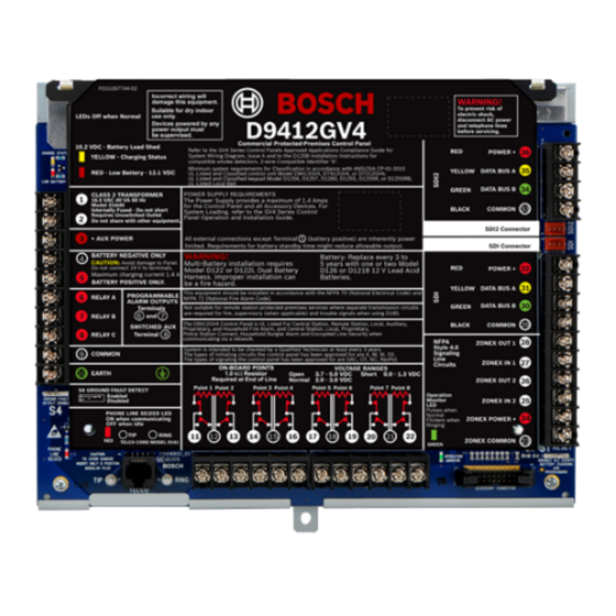
D9412GV4/D7412GV4 v2.03 | Installation and System Reference Guide | 15.0 Faceplates 15.0 Faceplates 15.1 D9412GV4/D7412GV4 v2.00 (and higher) Faceplate Figure 38: D9412GV4/D7412GV4 v2.00 (and higher) Faceplate Charging status LED (yellow) Ring Low battery LED (red) Operation monitor LED (green) Color-coded battery leads... -
Page 83: Specifications
SDI2 Bus B-: RJ31X or RJ38X jack can connect the control panels. Telephone Connection: Bosch Security Systems, Inc. D928 Dual Phone Line Module required for two phone line service Connections Two Telco on D9412GV4 and D7412GV4. Supervision supplied by the control panel. - Page 84 D9412GV4/D7412GV4 v2.03 | Installation and System Reference Guide | 16.0 Specifications Bosch Security Systems, Inc. | 7/16 | F01U265457-09...
-
Page 85: B520 Power Supply
D9412GV4/D7412GV4 v2.03 | Installation and System Reference Guide | 16.0 Specifications 16.2 B520 Power Supply Table 32: B520 Specifications Voltage Input Primary: 18 VAC 18.0 VAC 50 VA class 2 plug-in transformer (TR1850) (Power Secondary: Batt 1, Batt 2 The B520 Auxiliary Power Supply Module supports the connection of two... -
Page 86: Control Panel Terminal Wiring
D9412GV4/D7412GV4 v2.03 | Installation and System Reference Guide | 16.0 Specifications 16.3 Control panel Terminal Wiring Table 33: Terminal Wiring Requirements Terminal Terminal Requirements Description 18 AWG min (up to 14 AWG max) 18 AWG min (up to 14 AWG max) - Page 87 BUS A SDI2 POWER Terminal accommodates 14 to 22 AWG, use appropriate wire size based on peripheral device current *D9412GV4 only. Terminals 25 and 26 are NOT USED on the D7412GV4 Control Panel. Bosch Security Systems, Inc. | 7/16 | F01U265457-09...
-
Page 88: Approved Applications
D9412GV4/D7412GV4 v2.03 | Installation and System Reference Guide | 17.0 Approved Applications 17.3.1 Control Panel Enclosure 17.0 Approved Applications Requirements The UL System Chart (Table 38 on page 149) UL Standard 681 for Installation and references the components that are evaluated... -
Page 89: System Configuration Requirements
D9412GV4/D7412GV4 v2.03 | Installation and System Reference Guide | 17.0 Approved Applications UL Listed Model 5110 Bell All pass codes with authority to arm the safe or UL Listed Model 4001-42 External Line vault and also send a Closing Report must be Balancer valid in this area. -
Page 90: Four-Wire Smoke Detectors
D9412GV4/D7412GV4 v2.03 | Installation and System Reference Guide | 17.0 Approved Applications 17.4.1 Four-Wire Smoke Detectors When using four-wire smoke detectors, install a power supervision device according to the manufacturer’s instructions. You can connect any number of four-wire smoke detectors to the D9412GV4/D7412GV4 v2.03 Control Panels... -
Page 91: Two-Wire Smoke Detectors
D9412GV4/D7412GV4 v2.03 | Installation and System Reference Guide | 17.0 Approved Applications Use a D125B Powered Loop Interface 17.4.5 Other Devices. Module with two-wire initiating devices 17.4.2 Two-Wire Smoke Detectors for a D9412GV4/D7412GV4 v2.03 Two-wire smoke detectors connect to the Control Panel). -
Page 92: Other Devices
D9412GV4/D7412GV4 v2.03 | Installation and System Reference Guide | 17.0 Approved Applications 17.4.5 Other Devices Use a D130 Relay Module, D8129 OctoRelay, or Switched Aux (Terminal 8) to provide reset capability to other initiating devices such as: D125B Powered Loop Interface Module (2-wire smoke detector module) ... -
Page 93: Ul Listed Two-Wire Smoke Detectors Compatible With The D125B
D9412GV4/D7412GV4 v2.03 | Installation and System Reference Guide | 17.0 Approved Applications 17.4.6 UL Listed Two-Wire Smoke Detectors Compatible with the D125B A D125B Powered Loop Interface Module is required to connect smoke detectors to the on-board points (1-8). Table 34:... -
Page 94: Ul Listed Synchronization (Sync) Modules And Strobes Compatible With The D9412Gv4/D7412Gv4
D9412GV4/D7412GV4 v2.03 | Installation and System Reference Guide | 17.0 Approved Applications 17.4.7 UL Listed Synchronization (Sync) Modules and Strobes Compatible with the D9412GV4/D7412GV4 To be UL 864 9 edition compliant, you must use only these models of synchronization modules and strobes with the D9412GV4 and D7412GV4 Control Panels. - Page 95 D9412GV4/D7412GV4 v2.03 | Installation and System Reference Guide | 17.0 Approved Applications Table 35: Synchronization Module and Strobe Compatibility Synchronization Manufacturer Module Model Strobe Model Product Description System MDL3 PC24 Series PC24115 24 VDC, 115 cd, Red, Ceiling mount Sensor...
- Page 96 D9412GV4/D7412GV4 v2.03 | Installation and System Reference Guide | 17.0 Approved Applications AH Series Wall AH-24WP-R 24 VDC, Outdoor, Weatherproof, Red or Ceiling- mount Electronic Horns AS-241575W-FR AS Series 24 VDC, 15 cd, (75 cd on axis), Two-wire, Audible Wall-mount, Red...
- Page 97 D9412GV4/D7412GV4 v2.03 | Installation and System Reference Guide | 17.0 Approved Applications HS4-24MCWH- 24 VDC, 135 to 185 cd, Four-wire, Square, HS4-24MCWH- 24 VDC, 135 to 185 cd, Four-wire, Square, White NS Series Horn NS-241575W-FR 24 VDC, 15/75 cd, Red...
- Page 98 D9412GV4/D7412GV4 v2.03 | Installation and System Reference Guide | 17.0 Approved Applications RSSR-24110C- 24 VDC, 110 cd, Ceiling-mount, White 24 VDC, 75 cd, Ceiling-mount, White RSSR-2475C- RSSR-2475W- 24 VDC, 74 cd, Square, Wall-mount, Red RSSWP-2475W- 24 VDC, 75 cd, Waterproof, Red...
-
Page 99: Enclosures
24 VDC, Selectable 115/177 cd, Red ZRS-MCCH-FW 24 VDC, Selectable 115/177 cd, White 17.5 Enclosures Bosch Security Systems offers three optional enclosures for the control panel. Sections 17.5.1 D8103 Enclosure, 17.5.2 D8108A Enclosure, and 17.5.3 D8109 Red Fire Enclosure describe the three options. - Page 100 D9412GV4/D7412GV4 v2.03 | Installation and System Reference Guide | 17.6 Programming Options NOTICE TO USERS, INSTALLERS, AUTHORITIES HAVING JURISDICTION, AND OTHER INVOLVED PARTIES This product incorporates field-programmable software. In order for the product to comply with the requirements in the Standard for Control Units and Accessories for Fire Alarm Systems, UL 864, you must limit certain programming features or options to specific values.
- Page 101 D9412GV4/D7412GV4 v2.03 | Installation and System Reference Guide | 17.6 Programming Options Table 36: UL 864 Programming Requirements (continued) Product Feature/Option Permitted in Possible Settings Settings Permitted in UL 864? (Y/N) UL 864 Area # Fire Time 1 to 90 min...
- Page 102 Yes / No 17.6.2 Required Programming to Meet UL 636 When using a D9412GV4/D7412GV4 control panel for hold-up operation, a hold-up point should have the following setting applied to it: – P## Type = 0 (Point is constantly armed regardless of the status of the system.) –...
- Page 103 An off premise transmission means is required 17.6.4 ULC S304 Requirements To comply with UCL S304, the D9412GV4/D7412GV4 v2.00 (and up) control panels must follow the requirements below: Auto arming is not allowed for ULC S304 applications. Control units that support auto arming shall provide an audible signal throughout the protected area not less than 10 min prior to the auto arming taking place.
-
Page 104: Installer Menu
D9412GV4/D7412GV4 v2.03 | Installation and System Reference Guide | 18.0 Installer Menu 18.0 Installer Menu D9412GV4/D7412GV4 v2.03 Control Panels do not support the D5200 Programmer. Instead, you can perform limited programming and diagnostics using a keypad. Programming and diagnostics options appear on the keypad when you access the Main menu (Installer) option, which includes the Installer menu. - Page 105 D9412GV4/D7412GV4 v2.03 | Installation and System Reference Guide | 18.0 Installer Menu Conventions for this section This guide to the Keypad Installer menu provides instructions for using the keypad, based on the following conventions: All instructions access the Installer menu from the Main menu (Installer) option, not, not while in Service mode.
- Page 106 D9412GV4/D7412GV4 v2.03 | Installation and System Reference Guide | 18.0 Installer Menu Figure 39: Keypad Installer menu tree Bosch Security Systems, Inc. | 7/16 | F01U265457-09...
-
Page 107: Characters
D9412GV4/D7412GV4 v2.03 | Installation and System Reference Guide | 18.0 Installer Menu Escape, delete characters, and enter letters and special characters Escape from a menu. B91x/B92x/B93x keypads include a hard [ESC] key. To exit a menu and return to the previous level, press [ESC]. To exit and return to idle text from any level of the menu structure, press and hold [ESC]. -
Page 108: 1] Program Menu
D9412GV4/D7412GV4 v2.03 | Installation and System Reference Guide | 18.0 Installer Menu 18.1 [1] Program Menu With the Program Menu, you can program parameters to make your system operational, including phone number and format, enhanced communication options, primary and backup routes, and notifications. -
Page 109: 1] Reporting > [2] Network Menu Parameters
D9412GV4/D7412GV4 v2.03 | Installation and System Reference Guide | 18.0 Installer Menu Go to the [1] Program > [1] Reporting > [1] Phone > [1] Phone Format menu option. The keypad shows the phone number for the phone path. /[PREV] or /[NEXT] to go to the path you wish to edit. - Page 110 D9412GV4/D7412GV4 v2.03 | Installation and System Reference Guide | 18.0 Installer Menu Enhanced Comm Parms B91x/B92x keypads Configuration of Enhanced Comm Parms Enter the installer passcode, and then go to the [1] Installer menu. Go to the [1] Program > [1] Reporting > [2] Network > [2] Enhanced Comm Parms menu option.
- Page 111 D9412GV4/D7412GV4 v2.03 | Installation and System Reference Guide | 18.0 Installer Menu Port Number (seconds) B91x/B92x keypads Configuration of Port number Enter the installer passcode, and then go to the [1] Installer menu. Go to the [1] Program > [1] Reporting > [2] Network > [2] Enhanced Comm Parms menu option.
-
Page 112: 1] Reporting > [3] Routing Menu Parameters
D9412GV4/D7412GV4 v2.03 | Installation and System Reference Guide | 18.0 Installer Menu The [ESC] key acts as a [Backspace] key. Press [ESC] to delete the characters, and then enter the new numbers. Press [ENTER] to save the port number. The keypad shows Parameter Saved, and asks if you wish to edit the port number. - Page 113 D9412GV4/D7412GV4 v2.03 | Installation and System Reference Guide | 18.0 Installer Menu Primary Path Device B91x/B92x keypads Configuration of Primary Path Device Enter the installer passcode, and then open the [1] Installer menu. Go to the [1] Program > [1] Reporting > [3] Routing menu option. The keypad toggles between showing the current primary and backup setting for the routing path.
-
Page 114: 2] Network > [1] Bus Module (1) Or [2] Bus Module (2) Module Parameters
D9412GV4/D7412GV4 v2.03 | Installation and System Reference Guide | 18.0 Installer Menu Press [ENTER]. The keypad shows Set Route Device menu. Press [PREV] or [NEXT] to scroll through the list of devices (for path 1) and go to the Path 1 option you wish to select for the current device (for example, Phone 1). - Page 115 D9412GV4/D7412GV4 v2.03 | Installation and System Reference Guide | 18.0 Installer Menu DHCP/AutoIP Enable B91x/B92x keypads Configuration of DHCP/AutoIP Enable Enter the installer passcode, and then open the [1] Installer menu. Go to the [1] Program > [2] Network > [1] Bus Module (1) or [2] Bus Module (2) > [1] Module Parameter >...
-
Page 116: 2] Network > [1] Bus Module (1) Or [2] Bus Module (2) > [2] Address Parameters
D9412GV4/D7412GV4 v2.03 | Installation and System Reference Guide | 18.0 Installer Menu 18.1.5 [2] Network > [1] Bus Module (1) or [2] Bus Module (2) > [2] Address Parameters IP Address B91x/B92x keypads Configuration of IP Address Enter the installer passcode, and then open the [1] Installer menu. -
Page 117: 2] Network > [1] Bus Module (1) Or [2] Bus Module (2) > [3] Dns Parameters
D9412GV4/D7412GV4 v2.03 | Installation and System Reference Guide | 18.0 Installer Menu Enter the installer passcode, and then open the [1] Installer menu. Go to the [1] Program > [2] Network > [1] Bus Module (1) or [2] Bus Module (2) > [2] Address Parameter >... - Page 118 D9412GV4/D7412GV4 v2.03 | Installation and System Reference Guide | 18.0 Installer Menu Delete existing characters, if necessary, and then enter the new number. Use [PREV] or [NEXT] to move to a different byte. When finished, press [ENTER] to save the programming.
-
Page 119: 2] Network > [3] Cellular (Common) Menu Parameters
D9412GV4/D7412GV4 v2.03 | Installation and System Reference Guide | 18.0 Installer Menu B93x/B94x keypads Configuration of Module Hostname Enter the installer passcode, and then open the [1] Installer menu. Go to the [2] Network > [1] Bus Module (1) or [2] Bus Module (2) > [3] DNS Parameter >... -
Page 120: 3] Rps > [1] Rps Passcode Menu Parameters
D9412GV4/D7412GV4 v2.03 | Installation and System Reference Guide | 18.0 Installer Menu B93x/B94x keypads Configuration of SIM Username Enter the installer passcode, and then open the [1] Installer menu. Go to the [2] Network > [3] Cellular (common) > [2] SIM Username menu option. -
Page 121: 3] Rps > [2] Rps Phone Number Menu Parameters
D9412GV4/D7412GV4 v2.03 | Installation and System Reference Guide | 18.0 Installer Menu RPS Passcode B91x/B92x keypads Configuration of RPS Passcode Enter the installer passcode, and then open the [1] Installer menu. Go to the [1] Program > [3] RPS > [1] RPS Passcode menu option. -
Page 122: 3] Rps > [3] Rps Ip Address Menu Parameters
D9412GV4/D7412GV4 v2.03 | Installation and System Reference Guide | 18.0 Installer Menu 18.1.10 [3] RPS > [3] RPS IP Address Menu Parameters The control panel allows for enhanced communication to occur over the SDI bus. In this menu, you can program the IP address for RPS communication. -
Page 123: 4] Area Options Menu Parameters
D9412GV4/D7412GV4 v2.03 | Installation and System Reference Guide | 18.0 Installer Menu B93x/B94x keypads Configuration of RPS Port Number Enter the installer passcode, and then open the [1] Installer menu. Go to the [1] Program > [3] RPS > [4] RPS Port Number menu option. - Page 124 D9412GV4/D7412GV4 v2.03 | Installation and System Reference Guide | 18.0 Installer Menu Area On B91x/B92x keypads Configuration of Area On Enter the installer passcode, and then open the [1] Installer menu. Go to the [1] Program > [4] Area Options > [1] Area On menu option. The keypad display toggles between showing the Area On state and the account number for the selected areas.
-
Page 125: 5] Keypad > [1] Scope Menu Parameters
D9412GV4/D7412GV4 v2.03 | Installation and System Reference Guide | 18.0 Installer Menu Enter in the desired account number. The Cancel softkey allows you to cancel the changes. Press the Save softkey. When the keypad shows Parameter Saved, escape from the menu. -
Page 126: 6] Users Menu Parameters
D9412GV4/D7412GV4 v2.03 | Installation and System Reference Guide | 18.0 Installer Menu 18.1.14 [6] Users Menu Parameters The control panel can store up to 999 users. In this menu, you can edit user passcodes. Users B91x/B92x keypads Configuration of Users Enter the installer passcode, and then open the [1] Installer menu. - Page 127 D9412GV4/D7412GV4 v2.03 | Installation and System Reference Guide | 18.0 Installer Menu User (Passcode) Worksheet User User Area Authority Passcode User Name Group INSTALLER 123 __ __ __ ____ PASSCODE 123456 ____ USER 1 __ __ __ __ __ __ __ __ __...
-
Page 128: 7] Points Menu Parameters
D9412GV4/D7412GV4 v2.03 | Installation and System Reference Guide | 18.0 Installer Menu 18.1.15 [7] Points Menu Parameters Point indexes determine how points operate, and a point’s source gives a description as to the physical location of the point for installation and service personnel. In this menu, you can get program point indexes and sources. - Page 129 D9412GV4/D7412GV4 v2.03 | Installation and System Reference Guide | 18.0 Installer Menu Prompt Point Index # Type __(0)__ __(0)__ __(0)__ __(0)__ __(0)__ __(0)__ __(1)__ __(1)__ Point Response __(0)__ __(1)__ __(1)__ __(1)__ __(1)__ __(9)__ __(1)__ __(7)__ Entry Delay _(30)_ _(30)_ _(30)_...
- Page 130 D9412GV4/D7412GV4 v2.03 | Installation and System Reference Guide | 18.0 Installer Menu Point Index Description Defaults: Prt: Inst N/O Local:Dis Interior: Instant N/O Interior: Delay N/O Int: Inst N/O Local:Dis Interior: Follower N/O Maintained Keyswitch Momentary Keyswitch Open/Close on Fault...
- Page 131 D9412GV4/D7412GV4 v2.03 | Installation and System Reference Guide | 18.0 Installer Menu Prompt Point Index # Defer Bypass Report Cross Point Fire Point Alarm Verify Resettable Alarm Abort Wireless Point Supervision Time** (None) _____ _____ ____ ____ ____ ____ _____...
- Page 132 D9412GV4/D7412GV4 v2.03 | Installation and System Reference Guide | 18.0 Installer Menu Prompt Point Index # Invisible Point Buzz on Fault __(0)__ __(0)__ __(0)__ __(0)__ __(0)__ __(0)__ __(0)__ __(0)__ Watch Point Relay Response Type __(0)__ __(0)__ __(0)__ __(0)__ __(0)__ __(0)__...
- Page 133 D9412GV4/D7412GV4 v2.03 | Installation and System Reference Guide | 18.0 Installer Menu Point Point Point Area Point Point Point Area Point Point Source Index Assign Source Index Assign Source Wireless __ __ __ __ __ __ __ Point Point Point...
- Page 134 D9412GV4/D7412GV4 v2.03 | Installation and System Reference Guide | 18.0 Installer Menu Point Index B91x/B92x keypads Configuration of Point Index Enter the installer passcode, and then open the [1] Installer menu. Go to the [1] Program > [7] Points menu option. The keypad display toggles between showing the point index and point source for the selected point.
-
Page 135: 8] Disable Programming Menu Parameters
D9412GV4/D7412GV4 v2.03 | Installation and System Reference Guide | 18.0 Installer Menu RFID B91x/B92x keypads Configuration of RFID Enter the installer passcode, and then open the [1] Installer menu. Go to the [1] Program > [7] Points menu option. The keypad display toggles between showing the point index and point source for the selected point. -
Page 136: 2] Wireless Menu
D9412GV4/D7412GV4 v2.03 | Installation and System Reference Guide | 18.0 Installer Menu B93x/B94x keypads Configuration of Keypad Programming Enter the installer passcode, and then open the [1] Installer menu. Go to the [1] Program > [8] Disable Programming menu option. The keypad display shows that programming is enabled. -
Page 137: 1] Points > [2] Replace Point Rfid Menu Parameters
D9412GV4/D7412GV4 v2.03 | Installation and System Reference Guide | 18.0 Installer Menu 18.2.2 [1] Points > [2] Replace Point RFID Menu Parameters In this menu, you can replace RFID points. Replace Point RFID B91x/B92x keypads Configuration of Point RFID replacement Enter the installer passcode, and then open the [1] Installer menu. -
Page 138: 2] Repeaters > [1] Add Repeater Menu Parameters
D9412GV4/D7412GV4 v2.03 | Installation and System Reference Guide | 18.0 Installer Menu B93x/B94x keypads Configuration of Point RFID removal Enter the installer passcode, and then open the [1] Installer menu. Go to the [2] Wireless > [1] RF Points > [3] Remove Point RFID menu option. -
Page 139: 2] Repeaters > [2] Remove Repeater Menu Parameters
D9412GV4/D7412GV4 v2.03 | Installation and System Reference Guide | 18.0 Installer Menu Press [ENTER] to save the programming. When the keypad shows Repeater Replaced, escape from the menu. B93x/B94x keypads Configuration of Replace Repeater Enter the installer passcode, and then open the [1] Installer menu. - Page 140 D9412GV4/D7412GV4 v2.03 | Installation and System Reference Guide | 18.0 Installer Menu Press [ENTER] to view the state. The menu scrolls through the following sub-categories, with the results of the diagnostic check: State Tamper Low-Battery Maintenance When you finish viewing the information, press [PREV] and [ESC] to exit the menu.
-
Page 141: 3] Diagnostics > [2] Rf Repeaters
D9412GV4/D7412GV4 v2.03 | Installation and System Reference Guide | 18.0 Installer Menu Signal Strengths Level Margin When you finish viewing the information, press [PREV]/ and [ESC] to exit the menu. 18.2.8 [3] Diagnostics > [2] RF Repeaters You can obtain wireless point diagnostic information using a keypad and this menu. -
Page 142: 3] Diags Menu
D9412GV4/D7412GV4 v2.03 | Installation and System Reference Guide | 18.0 Installer Menu Press [ENTER] to view signal strength. The menu scrolls through the following sub-categories, with the results of the diagnostic check: Signal Strengths Level Margin When you finish viewing the information, press [PREV] and [ESC] to exit the menu. - Page 143 D9412GV4/D7412GV4 v2.03 | Installation and System Reference Guide | 18.0 Installer Menu B93x/B94x keypads use of Settings Enter the installer passcode, and then open the [1] Installer menu. Go to the [3] Diags > [2] Network > [1] Bus Module (1) or [2]Bus Module (2) > [1] Settings menu option.
-
Page 144: 3] Cellular Menu
D9412GV4/D7412GV4 v2.03 | Installation and System Reference Guide | 18.0 Installer Menu 18.3.3 [3] Cellular Menu You can obtain certain B44x diagnostic information using a keypad and this menu. Cellular (B44x diagnostics) B91x/B92x keypads use of Cellular Enter the installer passcode, and then open the [1] Installer menu. -
Page 145: 4] Srvc Byp Menu
D9412GV4/D7412GV4 v2.03 | Installation and System Reference Guide | 18.0 Installer Menu 18.4 [4] Srvc Byp Menu In this menu, you can edit the Service Bypass points. Service Bypass B91x/B92x keypads Configuration of Service Bypass Enter the installer passcode, and then open the [1] Installer menu. -
Page 146: 5] Versions Menu
D9412GV4/D7412GV4 v2.03 | Installation and System Reference Guide | 18.0 Installer Menu 18.5 [5] Versions Menu Use the Versions menu to view control panel version information. B91x/B92x keypads use of Versions Enter the installer passcode, and then open the [1] Installer menu. -
Page 147: Ul/Nfpa Compliant Installations
D9412GV4/D7412GV4 v2.03 | Installation and System Reference Guide | 19.0 UL/NFPA Compliant Installations Interface Modules 19.0 UL/NFPA Compliant Connect the DX4020 Network Interface Installations Module and the D9210C Access Control Interface Module to the SDI bus only if 19.1 Required Components... -
Page 148: Sdi2 Bus Devices
D9412GV4/D7412GV4 v2.03 | Installation and System Reference Guide | Using Zonex Bus 1 exclusively for fire B420 Ethernet Communication Module devices and Zonex Bus 2 exclusively for Only two devices can be installed at non-fire devices is acceptable. -
Page 149: Compatible Ul Listed Components
Compatible UL Listed Components 20.0 Compatible UL Listed Components In Table 38, the text in the columns and rows for D9412GV4/D7412GV4 v2.03 Control Panel have the following meanings: No = Not acceptable for this application Req. = Required for this application Opt. - Page 150 D9412GV4/D7412GV4 v2.03 | Installation and System Reference Guide | 20.0 Compatible UL Listed Components B915 Keypads Opt. Opt. Opt. Opt. Opt. Opt. Opt.**3 Opt.**3 Opt.**3 Opt.**3 B920 Keypads Opt. Opt. Opt. Opt. Opt. Opt. Opt.**3 Opt.**3 Opt.**3 Opt.**3 B921C Keypads Opt.
-
Page 151: Current Ratings Charts
D9412GV4/D7412GV4 v2.03 | Installation and System Reference Guide | 21.0 Current Ratings Charts 21.0 Current Ratings Charts 21.1 D8125MUX Complete the chart in Table 39 to determine the maximum currents for the D8125MUX and its accessories. Transfer the total figures to Table 41 on page 152. - Page 152 D9412GV4/D7412GV4 v2.03 | Installation and System Reference Guide | 21.0 Current Ratings Charts Table 40: Standby Battery Requirements Type Required Capacity Calculations Household Burglary + 4 min of alarm Bank Safe and Vault 72 h (UL 365). Auxiliary power current for all devices, including keypads, must be limited to 300 mA or less to meet this requirement.
- Page 153 D9412GV4/D7412GV4 v2.03 | Installation and System Reference Guide | 21.0 Current Ratings Charts D8130 ______ x Qty = ______ x Qty = ______ x Qty = ______ D9127T/U ______ x Qty = ______ x Qty = ______ x Qty = ______...
- Page 154 D9412GV4/D7412GV4 v2.03 | Installation and System Reference Guide | 21.0 Current Ratings Charts Table 42: UL/ULC Standby Battery Requirements Type Standby Alarm Other Requirements UL 609 Mercantile 15 min UL 609 Bank Safe and Vault 72 h (UL 365). Auxiliary power...
-
Page 155: Nfpa 72 Fire Alarm Applications
D9412GV4/D7412GV4 v2.03 | Installation and System Reference Guide | 22.0 NFPA 72 Fire Alarm Applications 22.0 NFPA 72 Fire Alarm Applications 22.1 Household Burglary and Commercial Burglary Four hours of standby battery capacity are required. 22.2 Bank Safe and Vault Because of changing regulations, verify the necessary time with your local authority having jurisdiction (AHJ). -
Page 156: Central Station Or Local Systems
D9412GV4/D7412GV4 v2.03 | Installation and System Reference Guide | 22.0 NFPA 72 Fire Alarm Applications 22.4 Central Station or Local Systems Central Station or Local Systems require 24 h of standby plus 5 min of alarm operation at the end of the 24-hour period. -
Page 157: Household Fire Warning Equipment
D9412GV4/D7412GV4 v2.03 | Installation and System Reference Guide | 22.0 NFPA 72 Fire Alarm Applications 22.6 Household Fire Warning Equipment The Household Fire Warning Equipment Standard requires 24 h of standby current plus 4 min of alarm operation at the end of the 24-hour period. Use battery Ah calculations to confirm compliance. The formula in Table 47 includes the calculation for 4 min of alarm operation at the end of the 24-hour period, and a 10% contingency factor that allows for depletion of battery capacity with age. -
Page 158: Ulc S304 Requirements
22.9 UL 636 To comply with UL 636, UL Standard for Holdup Alarm Units and Systems, the D9412GV4/D7412GV4 v2.03 control panels must be installed with either RADION receiver SD: B810 wireless receiver with a RADION panic transmitter: RFPB-A, or the Bosch Model B820 Inovonics Interface Module, Inovonics EchoStream Model EN4200 Serial Receiver and any of the following Inovonics EchoStream transmitters: EN1235SF, EN1235DF, or EN1249. -
Page 159: Appendix A: System Wiring Diagrams
D9412GV4/D7412GV4 v2.03 | Installation and System Reference Guide | Appendix A: System Wiring Diagrams Appendix A: System Wiring Diagrams Power Supply Side System Wiring Figure 40: D9412GV4/D7412GV4 v2.00 (and higher) Power Supply Side System (D113, D122/D122L, D928, D1640, D192G, D8132) Wiring (Power and Phone) - Page 160 D9412GV4/D7412GV4 v2.03 | Installation and System Reference Guide | Appendix A: System Wiring Diagrams Figure 41: Wiring D125B to G-series control panels 1 - Switched auxiliary power from the control panel’s 6 - Power-limited, supervised negative to B LOOP relay C.
-
Page 161: Input Points And Peripheral Devices Wiring Diagrams
D9412GV4/D7412GV4 v2.03 | Installation and System Reference Guide | Appendix A: System Wiring Diagrams Input Points and Peripheral Devices Wiring Diagrams Figure 42: D9412GV4/D7412GV4 v2.00 (and higher) Input Points and Peripheral Devices (D125B, D129, D130) System Wiring 1 - (Optional): For 24 V applications use a UL 1481 5 - 1k Ω... -
Page 162: Sdi And Zonex Devices System Wiring
D9412GV4/D7412GV4 v2.03 | Installation and System Reference Guide | Appendix A: System Wiring Diagrams SDI and Zonex Devices System Wiring Figure 43: D9412GV4 SDI and Zonex Devices (B420/B426, B450, D1255/D1255RB/D1256RB, D1257RB, D1265, D8125, D8128D, D8129, DX4020, ITS-DX4020-G, D9127U/T , D9210C) System Wiring... - Page 163 D9412GV4/D7412GV4 v2.03 | Installation and System Reference Guide | Appendix A: System Wiring Diagrams Figure 44: D7412GV4 SDI and Zonex Devices (B420/B426, B450, D1255/D1255RB/D1256RB, D1257RB, D1265, D8125, D8128D, D8129, DX4020, ITS-DX4020-G, D9127U/T , D9210C) System Wiring 1 - Up to 16 supervised D1265, D1255 (all versions),...
- Page 164 D9412GV4/D7412GV4 v2.03 | Installation and System Reference Guide | Appendix A: System Wiring Diagrams Figure 45: D9412GV4/D7412GV4 SDI2 Devices (B208, B308, B420/B426, B450, B520, B810, B820, B915/B920/B921C/B930/B942/B942W) System Wiring 1 - Up to 24 B208 Octo-input Modules 5 - Up to 1 B810 wireless receiver...
-
Page 165: Sdi2 Bus Wiring Recommendations
D9412GV4/D7412GV4 v2.03 | Installation and System Reference Guide | Appendix A: System Wiring Diagrams SDI2 Bus Wiring Recommendations Use the following SDI2 Bus wiring recommendations for SDI2 installation. The SDI2 Bus is used by the GV4 Control Panel and corresponding modules to communicate with one another. Modules can be connected via home run, daisy chain, or single level T-Tap anywhere on the SDI2 bus. - Page 166 D9412GV4/D7412GV4 v2.03 | Installation and System Reference Guide | Appendix A: System Wiring Diagrams 7350 5800 4828 4100 7000 5600 4700 4000 6666 5385 4516 3800 Use Non-shielded cable only. Maximum capacitance of 140nF (140,000 pf) per system. Contact the wire manufacturer for the capacitance ratings of the wire being used.
-
Page 167: Appendix B: Point Address Charts
D9412GV4/D7412GV4 v2.03 | Installation and System Reference Guide | Appendix B: Point Address Charts Appendix B: Point Address Charts Zonex 1 Points Place the labels on the base of the POPIT. Do not attach labels to the POPIT cover. ●... -
Page 168: Sdi2 Points
D9412GV4/D7412GV4 v2.03 | Installation and System Reference Guide | Appendix B: Point Address Charts B.2 SDI2 Points Not all off-board points supported by the control panel can be supported on B208 Octo-input modules. Points 9 and 10, 19 and 20, etc. can be supported by ZONEX bus or SDI2 Wireless points. - Page 170 Bosch Security Systems, Inc. 130 Perinton Parkway Fairport, NY 14450 www.boschsecurity.com © Bosch Security Systems, Inc., 2016...