Bosch D9412GV3 Operation And Installation Manual
Hide thumbs
Also See for D9412GV3:
- Installation instructions manual (28 pages) ,
- Quick reference manual (26 pages) ,
- Program entry manual (154 pages)
Table of Contents
Advertisement
Quick Links
Advertisement
Table of Contents

Related Manuals for Bosch D9412GV3


Summary of Contents for Bosch D9412GV3
- Page 1 D9412GV3/D7412GV3 Operation and Installation Guide Control Panels...
- Page 2 D9412GV3/D7412GV3 | Operation and Installation Guide | Trademarks Trademarks Federal Communications Commission (FCC) Rules CoBox is a registered trademark of Lantronix. Windows is a registered trademark of Microsoft Part 15 Corporation in the United States or in other countries. This equipment was tested and found to comply with...
- Page 3 D9412GV3/D7412GV3 | Operation and Installation Guide | Federal Communications Commission (FCC) Rules The telephone company might make changes in its facilities, equipment, operations, or procedures that could affect the operation of the equipment. If this happens, the telephone company provides advance notice in order for the necessary modifications to be made in order to maintain uninterrupted service.
-
Page 4: Table Of Contents
D9412GV3/D7412GV3 | Operation and Installation Guide | Contents Programming the Control Panel....17 Installing the Point Chart Label ..... 18 Contents Testing the System ......... 18 Introduction ............7 4.10 Service Walk Test ........... 18 Lightning Strikes ..........8 Power Supply ..........22 Effects ..............8... - Page 5 D9412GV3/D7412GV3 | Operation and Installation Guide | Contents Wiring Information for Installations Using the 11.3 D279A Independent Zone Control ....57 Rothenbuhler 5110/4001-42 High Security 11.4 Keyswitch ............57 Bell..............33 11.4.1 Description ............57 Off-Board Points..........36 11.4.2 Programming ........... 57 Point (Zonex) Bus: D9412GV3 Terminals and 11.4.3 Installation ............
- Page 6 D9412GV3/D7412GV3 | Operation and Installation Guide | Tables Figures Figure 36: D9412GV3, Input Points and Peripheral Devices System Wiring ......67 Figure 1: System Configuration ........9 Figure 37: D9412GV3, SDI Devices System Wiring Figure 2: Enclosure Mounting .........15 System Wiring........... 68 Figure 3: Enabling Ground Fault Detection...16...
-
Page 7: Introduction
This manual addresses the operation and installation of the D9412GV3 and D7412GV3 Control Panels. Throughout this guide, the words “control panel” refer to both control panels (D9412GV3 and D7412GV3). Table 2 on page 9 provides an overview of the differences in the control panels. -
Page 8: Lightning Strikes
D9412GV3/D7412GV3 | Operation and Installation Guide | 2.0 Lightning Strikes 2.0 Lightning Strikes The control panels are designed to significantly reduce electromagnetic interference and malfunction generally caused by lightning. Effects Any electronic system can be struck directly by lightning or be adversely affected by a lightning strike near the system. -
Page 9: Overview
D9412GV3/D7412GV3 | Operation and Installation Guide | 3.0 Overview 3.0 Overview Configuration and Parts Figure 1: System Configuration Table 2: GV3 Series Control Panel Differences Features D9412GV3 D7412GV3 D7212GV3 Yes - 8 doors Yes - 2 doors Access Control Arm/Disarm Passcodes... -
Page 10: Parts List
D9412GV3/D7412GV3 | Operation and Installation Guide | 3.0 Overview D1255B, D1255, D1256, D1260, D1260B 3.1.1 Parts List Keypad, or D720 Keypad The D9412GV3 andD7412GV3 Control Panels are D1255RB Fire Keypad, D1256RB Fire Keypad, or shipped assembled from the factory with the following... -
Page 11: Accessories
D9412GV3/D7412GV3 | Operation and Installation Guide | 3.0 Overview Accessories Refer to the Bosch Security Systems, Inc. product catalog for additional information. Table 3: Compatible Accessories Model Title UL 864 Fire Intrusion D122/D122L Dual Battery Harness D125B Powered Loop Interface Module... -
Page 12: Features In The D9412Gv3 And D7412Gv3
32 Control panel firmware v8.11 or later does not support the D5200. separate accounts in the D9412GV3, and up to 8 separate accounts in the D7412GV3. Assigning the same account number to different areas groups them UL requires that the DX4010i be used for together in a single account. -
Page 13: Keypads
D9412GV3/D7412GV3 | Operation and Installation Guide | 3.0 Overview 3.3.7 Keypads 3.3.9 Access Control Up to 32 unsupervised keypads can be connected to The D9412GV3 can control eight access doors (each the system. The available power, number of requiring the optional D9210B Wiegand Control... -
Page 14: Ground Fault Detection Added Feature
Use the Remote Programming Software (RPS), or the Enclosure Options local Programmers Menu, to program the D9412GV3 Mount the control panel assembly in any of the Bosch and D7412GV3 Control Panels. Refer to the Security Systems, Inc. enclosures listed: D9412GV3/D7412GV3 Program Entry Guide (P/N: ... -
Page 15: Installing The Control Panel
D9412GV3/D7412GV3 | Operation and Installation Guide | 4.0 Installation Figure 2: Enclosure Mounting 1 - Point chart label Enclosure mounting holes (5) 2 - Mounting skirt hooks (2) 7 - Mounting skirt hook holes (2) 3 - Module mounting holes (12) -
Page 16: Enabling Ground Fault Detection
D9412GV3/D7412GV3 | Operation and Installation Guide | 4.0 Installation If a ground fault condition occurs, the keypads display Table 5: Ground Fault Impedance SERVC GND FAULT and the control panel transmits Specifications a GROUND FAULT TROUBLE, AREA 1. When the control panel recognizes that the ground... -
Page 17: Completing The Installation
D9412GV3/D7412GV3 | Operation and Installation Guide | 4.0 Installation Completing the Installation Instructions for the D8125 POPEX Module, D8128D OctoPOPIT Module, D8129 OctoRelay If not already complete, make the earth ground Module, D811 Arm Status Relay Module, and connection to Terminal 10 and lock the reset pin in D928 Dual Phone Line Switcher appear in this the closed position. -
Page 18: Installing The Point Chart Label
D9412GV3/D7412GV3 | Operation and Installation Guide | 4.0 Installation Installing the Point Chart Label Only Walk Test Start and Walk Test End are reported to the central station. The point chart label is required for fire systems with verifications points. - Page 19 D9412GV3/D7412GV3 | Operation and Installation Guide | 4.0 Installation 6. After the last point is tested, 0 PTS TO TEST 5. To see the points that remain untested during the appears. Press [ESC]. The display shows ALL Service Walk Test: PTS TESTED briefly before returning to idle text.
-
Page 20: Figure 5: D9412Gv3 Service Walk Test Flow Chart
D9412GV3/D7412GV3 | Operation and Installation Guide | 4.0 Installation Figure 5: D9412GV3 Service Walk Test Flow Chart SERVICE WALK? [ENT] 246 PTS TO TEST [ESC] Test a device POINT TEXT (Text displays for 60 seconds) 245 PTS TO TEST [ESC]... -
Page 21: Figure 6: D7412Gv3 Service Walk Test Flow Chart
D9412GV3/D7412GV3 | Operation and Installation Guide | 4.0 Installation Figure 6: D7412GV3 Service Walk Test Flow Chart SERVICE WALK? [ENT] 75 PTS TO TEST [ESC] Test a device POINT TEXT (Text displays for 60 seconds) 74 PTS TO TEST [ESC]... -
Page 22: Power Supply
D9412GV3/D7412GV3 | Operation and Installation Guide | 5.0 Power Supply 4. Plug the transformer into an unswitched, 120 5.0 Power Supply VAC, 60 Hz power outlet only. 5. Secure the transformer to the outlet with the Primary Power Terminals 1 and 2 screw provided. -
Page 23: Figure 7: Battery Terminals
D9412GV3/D7412GV3 | Operation and Installation Guide | 5.0 Power Supply 3. Connect the black battery lead to Terminal 4, and Figure 7: Battery Terminals then to the negative (-) side of the battery. 4. Connect the red battery lead to Terminal 5, and then to the positive (+) side of the battery. -
Page 24: Replacing The Battery
D9412GV3/D7412GV3 | Operation and Installation Guide | 5.0 Power Supply 5.2.3 Replacing the Battery Figure 9: Charging and Battery LEDs Replace batteries every 3 to 5 years under normal use. Record the date of installation directly on the battery. L EDs Off When No rmal... -
Page 25: Battery Discharge And Recharge Schedule
D9412GV3/D7412GV3 | Operation and Installation Guide | 5.0 Power Supply Reset the control panel by momentarily placing the 5.2.6 Battery Discharge and Recharge Schedule reset pin in the disable position. Refer to Figure 4 on Table 6: Battery Discharge and Recharge page 16. -
Page 26: Power Outputs
D9412GV3/D7412GV3 | Operation and Installation Guide | 6.0 Power Outputs Total Available Power 6.0 Power Outputs The system produces up to 1.4 A of combined power at 12.0 VDC nominal for special application use. The Circuit Protection outputs listed below share the available power. These Three self-resetting circuit breakers protect the control outputs are shown as red circles on the faceplate. -
Page 27: Programmable Power Output Terminals 6, 7, And 8
D9412GV3/D7412GV3 | Operation and Installation Guide | 6.0 Power Outputs Power Restricted for Fire and Combined Fire and Programmable Power Output Burglary Systems: Fire systems are prohibited from Terminals 6, 7, and 8 using the battery for determining alarm power. Use 6.4.1... -
Page 28: Telephone Connections
D9412GV3/D7412GV3 | Operation and Installation Guide | 7.0 Telephone Connections Figure 10: RJ31X Wiring 7.0 Telephone Connections Registration RJ31X RING (red) TIP (green) The Bosch Security Systems, Inc. D9412GV3 and D7412GV3 Control Panels are registered with the Federal Communication Commission (FCC) under... -
Page 29: Phone Led (Red)
D9412GV3/D7412GV3 | Operation and Installation Guide | 7.0 Telephone Connections Bad Line Might Test OK: The telephone line monitor Phone LED (Red) uses voltage levels to test the status of the telephone The red Phone LED illuminates when the control line. -
Page 30: D928 Dual Phone Line Switcher
D9412GV3/D7412GV3 | Operation and Installation Guide | 7.0 Telephone Connections 7.11 D928 Dual Phone Line Switcher Figure 12: D928 Dual Phone Line Switcher 7.11.1 Description The optional D928 Dual Phone Line Switcher allows the control panel to send reports over two separate telephone lines. -
Page 31: Installing The D928
D9412GV3/D7412GV3 | Operation and Installation Guide | 8.0 On-Board Points Phone Line Fail LEDs 7.11.3 Installing the D928 Two yellow Phone Line Status LEDs (one for the Mounting primary telephone line, one for the secondary Mount the D928 on the lower right side of the... -
Page 32: Point Parameters
D9412GV3/D7412GV3 | Operation and Installation Guide | 8.0 On-Board Points Point Parameters Table 9: Point Parameters The condition of on-board Points 1 to 8 is determined by measuring the voltage across the point input Loop Voltage Range terminal and one of the common terminals. The Open Greater than 3.7 VDC, but less than 5.0... -
Page 33: Point Response Time
D9412GV3/D7412GV3 | Operation and Installation Guide | 8.0 On-Board Points Point Response Time Wiring Information for Installations Using the Rothenbuhler The control panel scans on-board and off-board point 5110/4001-42 High Security Bell sensor loops every 300 ms. The Debounce program... - Page 34 D9412GV3/D7412GV3 | Operation and Installation Guide | 8.0 On-Board Points Figure 14: Rothenbuhler 5110/4001-42 High Security Bell Wiring Configuration 0.64 mm (1/4 in.) minimum distance 1 - Self-contained vibration sensor 10 - D126 Battery 2 - Control panel 11 - D8108A Enclosure...
-
Page 35: Figure 15: Wiring The Rothenbuhler 5110/4001-42
D9412GV3/D7412GV3 | Operation and Installation Guide | 8.0 On-Board Points Figure 15: Wiring the Rothenbuhler 5110/4001-42 High Security Bell to the D9412GV3 or D7412GV3 Control Panel RE D B L K 1 2 3 N/O 1 COMM 1 N/C 1... -
Page 36: Off-Board Points
D9412GV3/D7412GV3 | Operation and Installation Guide | 9.0 Off-Board Points Table 10: POPEX Modules 9.0 Off-Board Points Point (Zonex) Bus: D9412GV3 Model Power Data Terminals and D7412GV3 D9412G Terminals 23 and 24 Terminals 25 and 26 Terminals Terminals 27 and 28 9.1.1... -
Page 37: D9412Gv3/D7412Gv3 Responses To Missing Point Conditions
119 POPIT points. Connect two D8125 Modules to the application. the D9412GV3 to bring the combined total number of POPIT and on-board points to 246. Points 9 to 127 connect to the first POPEX Module. -
Page 38: Figure 16: Connecting The D8125 Popex To The D9412Gv3 Control Panel
D9412GV3/D7412GV3 | Operation and Installation Guide | 9.0 Off-Board Points Figure 16: Connecting the D8125 POPEX to the D9412GV3 Control Panel 1 - D8125 POPEX Module 5 - Zone expansion loop 2 - Switch block 6 - Up to 119 POPITs... -
Page 39: Figure 17: Connecting The D8125 Popex To The D7412Gv3 Control Panel
D9412GV3/D7412GV3 | Operation and Installation Guide | 9.0 Off-Board Points Figure 17: Connecting the D8125 POPEX to the D7412GV3 Control Panel Reset Pin Dis able all exc ept Bat ter y R ED - Lo w Batter y - Cha rg ing a nd Pr ogr am min g... -
Page 40: Installing The D8125 Popex Module
D7212GV3. The other set is marked “Bank 2” for required. Refer to Table 13 to determine the wire use with the D9412GV3 and D9112. Use the sheets gauge for the length of each data expansion loop. later to label the POPITs. Refer to Section 9.3.6 POPIT Module Point Assignments on page 42. -
Page 41: Wiring Data Expansion Loops To Popex Modules
D9412GV3/D7412GV3 | Operation and Installation Guide | 9.0 Off-Board Points 9.3.4 Wiring Data Expansion Loops to POPEX 9.3.7 Program Record Sheet Modules The first column of the table in Figure 18 on page 42 Each POPEX Module has two positive (+) and two contains the POPIT Switch Settings for the D9127 negative (-) data expansion loop terminals. -
Page 42: Popit Labels
Intrusion Alarm Systems in the and 129 to 247. The D7412GV3 uses Points 9 to 75 D9412GV3/D7412GV3 Approved only. The D9412GV3 reserves Points 128 and 248 for Applications Compliance Guide internal use. POPITs must be connected for Points (P/N: F01U143069) for important... -
Page 43: Listings
D9412GV3/D7412GV3 | Operation and Installation Guide | 9.0 Off-Board Points 9.4.2 Listings Figure 19: D8128D OctoPOPIT Layout The D8128D OctoPOPIT Module is UL Listed for Local or Police Connected Burglary Alarm, Central Station Burglary Alarm, Household Burglary Alarm applications, and commercial fire applications (UL 864 and NFPA 72). -
Page 44: Installation
D9412GV3/D7412GV3 | Operation and Installation Guide | 9.0 Off-Board Points 9.4.3 Installation Table 14: D8128D OctoPOPIT Switch Settings For the most effective installation, use the following for D9412GV3 and D7412GV3 four-step process: 1. Set the OctoPOPIT switches. Refer to Section... -
Page 45: Mounting Octopopits
D9412GV3/D7412GV3 | Operation and Installation Guide | 9.0 Off-Board Points Use the point DIP switches to disable conflicting 9.4.6 Wiring OctoPOPITs points, such as when a D9210B Access Control Warning: Disconnect all power to the Module must be assigned to a point that falls within control panel before beginning any work the range of the D8128D OctoPOPIT. -
Page 46: Figure 20: Connecting D8128D Octopopits To The
D9412GV3/D7412GV3 | Operation and Installation Guide | 9.0 Off-Board Points Figure 20: Connecting D8128D OctoPOPITs to the D9412GV3 1 - Zonex Bus 1, Switch 1 ON (Points 9 to 72) 7 - Zonex Bus 2, Switch 1 ON (Points 129 to... -
Page 47: Figure 21: Connecting D8128D Octopopits To The
D9412GV3/D7412GV3 | Operation and Installation Guide | 9.0 Off-Board Points Figure 21: Connecting D8128D OctoPOPITs to the D7412GV3 1 - Zonex 1 address 2 - Sensor loops Refer to Address Switches in Section 9.4.4 Setting the OctoPOPIT Switches on page 44 for information about making these switch settings. -
Page 48: Figure 22: Wiring Multiple D8128Ds Using Molex ® Table 17: Connectors
D9412GV3/D7412GV3 | Operation and Installation Guide | 9.0 Off-Board Points ® Using Molex Connectors Each D8128D Module is supplied with a 30 cm (12 in.) female-to-female Molex cable assembly. P1 and P2 are Molex connectors that parallel the COM, IN, OUT, and +12.0 VDC terminals on the terminal strip. -
Page 49: Octopopit Sensor Loops
D9412GV3/D7412GV3 | Operation and Installation Guide | 9.0 Off-Board Points 9.4.7 OctoPOPIT Sensor Loops Figure 23: D8128D OctoPOPIT Sensor Loops Only the resistance on the loop limits the number of normally-open or normally-closed detection devices each sensor loop can supervise. Resistance on each sensor loop must be less than 100 ... -
Page 50: Off-Board Relays
D9412GV3/D7412GV3 | Operation and Installation Guide | 10.0 Off-Board Relays OctoRelays for relay numbers 1 to 64 connect to 10.0 Off-Board Relays Zonex 1, Terminal 28. OctoRelays for relay numbers 65 to 128 connect to Zonex 2 (D9412GV3 only), 10.1 D8129 OctoRelay Terminal 26 on the D9412GV3. -
Page 51: Configuring The D8129 Octorelay
D9412GV3/D7412GV3 | Operation and Installation Guide | 10.0 Off-Board Relays Figure 25: D8129 Connections to the D7412GV3 1 - D8129 OctoRelays for relay numbers 1 to 64. 2 - Power limited Connect OctoRelays in parallel. 10.1.2 Relay Outputs 10.1.1 Configuring the D8129 OctoRelay... -
Page 52: Wiring Connections
D9412GV3/D7412GV3 | Operation and Installation Guide | 10.0 Off-Board Relays 1. Align the module with one of the mounting 10.2 D811 Arm Status Relay Module locations in the enclosure (refer to Figure 2 on The D811 Arm Status Relay Module allows the page 9). -
Page 53: Wiring Connections
D9412GV3/D7412GV3 | Operation and Installation Guide | 10.0 Off-Board Relays Use the D137 Mounting Bracket or D9002 10.2.3 Wiring Connections Mounting Skirt to install D811 Modules in Power down the control panel to connect D811 enclosures with no available module mounting Modules as shown in Figure 26 on this page and locations. - Page 54 D9412GV3/D7412GV3 | Operation and Installation Guide | 10.0 Off-Board Relays Figure 27: D811 Module Wiring to the D7412GV3 1 - D811 for Relay 53 Bosch Security Systems, Inc. | 10/10 | F01U143070-03...
-
Page 55: Arming Devices
D9412GV3/D7412GV3 | Operation and Installation Guide | 11.0 Arming Devices D1260/D1260B: Easy-to-read, 4-line by 20- 11.0 Arming Devices character LCD display with eight “soft” keys to display simple selections. Addressable SDI 11.1 Description Addresses 1-8. D720/D720B: LED display keypad appropriate for... -
Page 56: Installation
D9412GV3/D7412GV3 | Operation and Installation Guide | 11.0 Arming Devices 11.2.2 Installation Extra Power for More Keypads Refer to the keypad installation manuals for The D1255 and D1255B Keypads draw 104 mA when installation and mounting instructions. Keypads idle. They draw 206 mA with the keys lit and the connect to the control panel in parallel (Table 20). -
Page 57: D279A Independent Zone Control
LEDs for keyswitch arming stations. Refer to Relays in the D9412GV3/D7412GV3 Program Entry Guide (P/N: F01U170807). 11.4.2 Programming Refer to Point Assignments in the D9412GV3/D7412GV3 Program Entry Guide (P/N: F01U170807) for the correct programming for points used for keyswitches. 11.4.3 Installation For maintained switches, connect the EOL resistor for the point at the keyswitch so that the switch opens the circuit when it operates. -
Page 58: Figure 29: Keyswitch Wiring
D9412GV3/D7412GV3 | Operation and Installation Guide | 11.0 Arming Devices Momentary Contact If the point to which the keyswitch is connected is programmed for a momentary contact, shorting the arming circuit toggles the area’s arming state between armed and disarmed. All faulted points are force armed, regardless of the entry in the FA Bypass Max program item. -
Page 59: Sdi Devices
D9412GV3/D7412GV3 | Operation and Installation Guide | 12.0 SDI Devices 12.3 D9131A Parallel Printer Interface 12.0 SDI Devices Module The Bosch Security Systems, Inc. D9131A Parallel 12.1 Description Printer Interface Module is a four-wire powered device D9412GV3 and D7412GV3 Control Panels can... -
Page 60: D9210B Wiegand Control Interface Module
D9412GV3/D7412GV3 | Operation and Installation Guide | 12.0 SDI Devices 12.4 D9210B Wiegand Control Interface 12.5 SDI Addresses 88 and 92 Module SDI Addresses 88 and 92 are available with the D9412GV3 and D7412GV3 Control Panels and are The Bosch Security Systems, Inc. D9210B Wiegand used for several different applications. -
Page 61: Network Interface Modules
D9412GV3/D7412GV3 | Operation and Installation Guide | 12.0 SDI Devices 12.5.2 Network Interface Modules Figure 30: DX4020 DIP Switch Settings The Bosch Security Systems, Inc. DX4020 Network Interface Module is a four-wire powered SDI device that provides connection for two-way communication over Ethernet networks to D9412GV3 and D7412GV3. -
Page 62: Programmer And Accessory Connections
D9412GV3/D7412GV3 | Operation and Installation Guide | 13.0 Programmer and Accessory Connections Accessing Local Keypad Programming when the 13.0 Programmer and Control Panel is Operating (Reset Switch Open) Accessory Connections To access the Local Programmers Menu while the control panel is operating: 13.1... -
Page 63: Accessory Connector
D9412GV3/D7412GV3 | Operation and Installation Guide | 13.0 Programmer and Accessory Connections 13.4 Accessory Connector Use the accessory connector to connect the control panel to the D928 Dual Phone Line Switcher. The accessory connector is on the bottom right corner of the I/O board (Figure 32). -
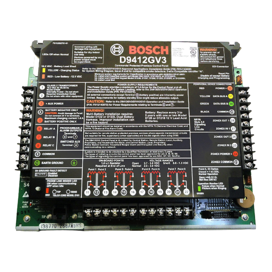
Page 64: Faceplates
D9412GV3/D7412GV3 | Operation and Installation Guide | 14.0 Faceplates 14.0 Faceplates 14.1 D9412GV3 Faceplate Figure 33: D9412GV3 Faceplate 1 - Charging status LED (yellow) 8 - Ring 2 - Low battery LED (red) 9 - S3, Point 8 EOL selection... -
Page 65: D7412Gv3 Faceplate
D9412GV3/D7412GV3 | Operation and Installation Guide | 14.0 Faceplates 14.2 D7412GV3 Faceplate Figure 34: D7412GV3 Faceplate 1 - Charging status LED (yellow) 8 - Ring 2 - Low battery LED (red) 9 - S3, Point 8 EOL selection 3 - Color-coded battery leads... -
Page 66: Appendix A: System Wiring Diagrams, Issue A
D9412GV3/D7412GV3 | Operation and Installation Guide | Appendix A: System Wiring Diagrams, Issue A Appendix A: System Wiring Diagrams, Issue A D9412GV3 Control Panel Figure 35: D9412GV3, Power Supply Side System Wiring 1 - If required by local AHJ, connect D113 Battery 9 - To Relay A or Relay B Lead Supervision Module. -
Page 67: Figure 36: D9412Gv3, Input Points And Peripheral Devices System Wiring
D9412GV3/D7412GV3 | Operation and Installation Guide | Appendix A: System Wiring Diagrams, Issue A Figure 36: D9412GV3, Input Points and Peripheral Devices System Wiring 1 - (Optional): For 24 V applications use a UL 1481 5 - P105BL1 1 kW resistor (P/N: F01U033966): listed, regulated, power-limited 24 VDC power For typical burglar alarm applications. -
Page 68: Figure 37: D9412Gv3, Sdi Devices System Wiring System Wiring
D9412GV3/D7412GV3 | Operation and Installation Guide | Appendix A: System Wiring Diagrams, Issue A Figure 37: D9412GV3, SDI Devices System Wiring System Wiring 1 - Up to 16 supervised D1255 (all versions), D1255RB, 7 - D8125 POPEX No.1 D1256, D1256RB Keypads, or D1257RB or D1257 Fire 8 - D8125 POPEX No. -
Page 69: D7412Gv3 Control Panel
D9412GV3/D7412GV3 | Operation and Installation Guide | Appendix A: System Wiring Diagrams, Issue A D7412GV3 Control Panel Figure 38: D7412GV3, Power Supply Side System Wiring If required by local AHJ, connect D113 Battery 9 - To Relay A or Relay B Lead Supervision Module. -
Page 70: Figure 39: D7412Gv3, Input Points And Peripheral Devices System Wiring
D9412GV3/D7412GV3 | Operation and Installation Guide | Appendix A: System Wiring Diagrams, Issue A Figure 39: D7412GV3, Input Points and Peripheral Devices System Wiring 1 - (Optional): For 24 V applications use a UL 1481 5 - P105BL1 1 k... -
Page 71: Figure 40: D7412Gv3, Sdi Devices System Wiring
D9412GV3/D7412GV3 | Operation and Installation Guide | Appendix A: System Wiring Diagrams, Issue A Figure 40: D7412GV3, SDI Devices System Wiring 1 - Up to 16 supervised D1255 (all versions), DX4020 Network Interface Module or other D1255RB, D1256, D1256RB Keypads, or... -
Page 72: Appendix B: Point Address Charts
D9412GV3/D7412GV3 | Operation and Installation Guide | Appendix B: Point Address Charts Appendix B: Point Address Charts Zonex 1, Points 9 to 127 (D9412GV3); Zonex 1, Points 9 to 75 (D7412GV3) Place the labels on the base of the POPIT. Do not attach labels to the POPIT cover. -
Page 73: Zonex 2, Points 129 To 247 (D9412Gv3 Only)
D9412GV3/D7412GV3 | Operation and Installation Guide | Appendix B: Point Address Charts Zonex 2, Points 129 to 247 (D9412GV3 Only) Place the labels on the base of the POPIT. Do not attach labels to the POPIT cover. A number in the switch column indicates that the switch is set to ON. -
Page 74: Specifications
Current Control Panel: Idle 225 mA; Alarm 300 mA Requirements Refer to the Current Rating Chart for Standby Battery Calculations section in the D9412GV3/D7412GV3 Approved Applications Compliance Guide (P/N: F01U143069) for the current draw requirements of other system components. Power All external connections are power-limited except battery terminals. - Page 75 D9412GV3/D7412GV3 | Operation and Installation Guide | Notes Notes Bosch Security Systems, Inc. | 10/10 | F01U143070-03...
- Page 76 Bosch Security Systems, Inc. 130 Perinton Parkway Fairport, NY 14450 www.boschsecurity.com © Bosch Security Systems, Inc., 2010...