Bosch D9412GV4 Installation And Operation Manual
Hide thumbs
Also See for D9412GV4:
- Owner's manual (214 pages) ,
- Program entry manual (210 pages) ,
- Installation and system reference manual (170 pages)
Table of Contents
Advertisement
Quick Links
Advertisement
Table of Contents

Related Manuals for Bosch D9412GV4


Summary of Contents for Bosch D9412GV4
- Page 1 Control Panels D9412GV4/D7412GV4/D7212GV4 Installation and Operation Guide...
-
Page 2: Rules
D9412GV4/D7412GV4/D7212GV4 | Installation and Operation Guide | Trademarks Department of Defense (DOD) Trademarks The D9412GV4/D7412GV4 was granted approval for Department of Defense (DoD) installations in Trademark names are used throughout this Sensitive Compartmented Information Facilities document. In most cases, these designations are (SCIF). - Page 3 (Contact your state public utilities commission for information.) FCC Registration Number: US:ESVOT00BD9412GV4 Service Center in USA: Bosch ST Service Center 8601 East Cornhusker Hwy Dock B Lincoln, NE 68507 9702 USA Ringer Equivalence: 0.0B Bosch Security Systems, Inc. | 3/12 | F01U266054-01...
-
Page 4: Table Of Contents
Called Party Disconnect 4.5.5 Locking the Reset Pin ........18 Communication Failure 7.10 Completing the Installation ......18 7.11 D928 Dual Phone Line Switcher 4.6.1 Charging the Battery ........18 7.11.1 Description Bosch Security Systems, Inc. | 3/12 | F01U266054-01... - Page 5 10.0 Off-Board Relays ..........56 13.4 B308 Octo-output Module 10.1 D8129 OctoRelay 13.4.1 Address Settings 10.1.1 Configuring the D8129 OctoRelay 13.4.2 Supervision 10.1.2 Relay Outputs 13.5 B420 Ethernet Communication Module 10.1.3 Installation Bosch Security Systems, Inc. | 3/12 | F01U266054-01...
- Page 6 Interconnect Wiring 15.0 Accessory Connector ......... 74 Figure 20: D8128D OctoPOPIT Sensor Loops 16.0 Faceplates ............75 Figure 21: D8129 Connections to the D9412GV4 16.1 GV4 Series Faceplate Appendix A: System Wiring Diagrams ..... 76 Figure 22: D8129 Connections to the D7412GV4...
-
Page 7: Introduction
This manual addresses the operation and installation of the GV4 Series Control Panels. Throughout this guide, the words “control panel” refer to all control panels (D9412GV4, D7412GV4 and D7212GV4). Table 2 on page 9 provides an overview of the differences in the control panels. -
Page 8: Lightning Strikes
D9412GV4/D7412GV4/D7212GV4 | Installation and Operation Guide | 2.0 Lightning Strikes 2.0 Lightning Strikes The control panels are designed to significantly reduce electromagnetic interference and malfunction generally caused by lightning. Effects Any electronic system can be struck directly by lightning or be adversely affected by a lightning strike near the system. -
Page 9: Overview
D9412GV4/D7412GV4/D7212GV4 | Installation and Operation Guide | 3.0 Overview 3.0 Overview Configuration and Parts Figure 1: System Configuration Table 2: Control Panel Differences Features D9412GV4 D7412GV4 D7212GV4 Access Control Yes - 8 doors Yes - 2 doors Arm/Disarm Passcodes Cards/Tokens... -
Page 10: Parts List
D9412GV4/D7412GV4/D7212GV4 | Installation and Operation Guide | 3.0 Overview D1255B, D1255, D1256, D1260, D1260B 3.1.1 Parts List Keypad, or D720 Keypad The control panels are shipped assembled from D1255RB Fire Keypad, D1256RB Fire Keypad, the factory with the following parts:... -
Page 11: Accessories
D9412GV4/D7412GV4/D7212GV4 | Installation and Operation Guide | 3.0 Overview Accessories Refer to the Bosch Security Systems, Inc. product catalog for additional information. Table 3: Compatible Accessories Model Title UL 864 Fire Intrusion B208 Octo-input Module B308 Octo-output Module B420 Ethernet Communication Module... -
Page 12: Features In The Gv4 Series Control Panels
D9412GV4/D7412GV4/D7212GV4 | Installation and Operation Guide | 3.0 Overview Interface Module, or D8125MUX Modules. The Features in the GV4 Series Control SDI2 bus supports any combination of B208 Panels Octo-input modules, or a B820 SDI2 Inovonics 3.3.1 SDI Interconnect Wiring Interface Module. -
Page 13: Keypads
D9412GV4/D7412GV4/D7212GV4 | Installation and Operation Guide | 3.0 Overview The system can route groups of Event Reports to four different destinations through the phone or UL requires all Fire System keypads to over a network. Each report group can be be supervised. -
Page 14: Event Memory
D9412GV4/D7412GV4/D7212GV4 | Installation and Operation Guide | 3.0 Overview 3.3.10 Event Memory 3.3.14 Conettix Functions The control panel retains point alarm and trouble The D6600 Conettix System supports data events in memory for each area. A D1255 (any network communications. Conettix allows the... -
Page 15: Other Features
D9412GV4/D7412GV4/D7212GV4 | Installation and Operation Guide | 3.0 Overview F01U215232) for details on installation, configuration and operation of this feature. 3.3.17 Other Features The GV4 Series Control Panels have many programmable features. Some of the features are listed below. Complete details on all features are... -
Page 16: Installation
D9412GV4/D7412GV4/D7212GV4 | Installation and Operation Guide | 4.0 Installation Enclosure Options 4.0 Installation Mount the control panel assembly in any of the Bosch Security Systems, Inc. enclosures listed: Installation Preparation D8103 Universal Enclosure (tan) This section contains a general installation ... -
Page 17: Installing The Control Panel
D9412GV4/D7412GV4/D7212GV4 | Installation and Operation Guide | 4.0 Installation When the control panel recognizes that the Installing the Control Panel ground fault condition is corrected, and remains 1. Place the control panel over the inside back corrected for between 5 to 45 consecutive sec, a of the enclosure, aligning the large Restoral Report is sent. -
Page 18: Locking The Reset Pin
D9412GV4/D7412GV4/D7212GV4 | Installation and Operation Guide | 4.0 Installation Table 5: Ground Fault Impedance Figure 4: Reset Pin Specifications Impedance Control Panel Detects Ground Fault ≤ 300 Ω 300 Ω to Detection depends upon the 200 kΩ terminal ≥ 200 kΩ... -
Page 19: Installing And Wiring Detection Devices
D9412GV4/D7412GV4/D7212GV4 | Installation and Operation Guide | 4.0 Installation 4.6.2 Installing and Wiring Detection Devices Yellow Charging Status LED Remains Lit: If the yellow charging status LED remains lit after five Install and wire detection devices and keypads at minutes of powering up the control panel, either their locations throughout the premises. -
Page 20: Service Walk Test
D9412GV4/D7412GV4/D7212GV4 | Installation and Operation Guide | 4.0 Installation Service Walk Test Procedure Test after initially programming the control panel. Refer to Figure 5 on page 23 for Service Walk Test options. Refer to the Walk Test procedures To meet UL 864 requirements, in the D9412GV4/D7412GV4/D7212GV4 Owner’s... - Page 21 D9412GV4/D7412GV4/D7212GV4 | Installation and Operation Guide | 4.0 Installation d. Press [NEXT] to see a list of the points the D9412GV4/D7412GV4/D7212GV4 Program that have not yet been tested. Move Entry Guide (P/N: F01U218312). through this list by pressing the [NEXT] 4.11.2 Service Bypass...
- Page 22 D9412GV4/D7412GV4/D7212GV4 | Installation and Operation Guide | 4.0 Installation 4.11.5 RF Diagnostics With a B820 SDI2 Inovonics Interface Module installed, the control panel can show detailed wireless communication information for RF points, keyfobs and repeaters. The RF Diagnostics menu can show real-time signal strength information for enrolled RF devices.
-
Page 23: Figure 5: Service Walk Test Flow Chart Example
D9412GV4/D7412GV4/D7212GV4 | Installation and Operation Guide | 4.0 Installation Figure 5: Service Walk Test Flow Chart Example SERVICE WALK? [ENT] 246 PTS TO TEST [ESC] Test a device POINT TEXT (Text displays for 60 seconds) 245 PTS TO TEST [ESC]... -
Page 24: Power Supply
D9412GV4/D7412GV4/D7212GV4 | Installation and Operation Guide | 5.0 Power Supply AC wiring can induce noise and low level 5.0 Power Supply voltage into adjacent wiring. Route data wiring away from AC and telephone wiring. Primary Power Terminals 1 and 2 Always connect the battery first and 5.1.1... -
Page 25: Installing The Battery
D9412GV4/D7412GV4/D7212GV4 | Installation and Operation Guide | 5.0 Power Supply Caution: When connecting two D1218 Caution: The battery terminals and Batteries to the control panel, both wire are not power limited. A 6.4 mm must have the same capacity (use two (0.250 in.) space must be maintained... - Page 26 D9412GV4/D7412GV4/D7212GV4 | Installation and Operation Guide | 5.0 Power Supply Figure 7: Non-Power-Limited Wiring 1 - Conduit required for use with external 4 - Relay output wires batteries. 5 - Input or Zone wires 2 - Battery wires 6 - Standby battery 3 - 6.4 mm (0.25 in.) minimum.
-
Page 27: Replacing The Battery
D9412GV4/D7412GV4/D7212GV4 | Installation and Operation Guide | 5.0 Power Supply When battery voltage returns to 13.7 VDC, the 5.2.3 Replacing the Battery Low Battery LED turns off and the keypad or Replace batteries every 3 to 5 years under normal keypads clear the SERVC LOW BATT message. -
Page 28: Battery Discharge And Recharge Schedule
D9412GV4/D7412GV4/D7212GV4 | Installation and Operation Guide | 5.0 Power Supply Overcharge Load Shed With AC Present: If more than 1.4 A of auxiliary current draw from the control panel occurs, the battery supplies the current and begins to discharge. If this situation is not corrected, the battery continues to discharge and at 11.8 VDC to... - Page 29 D9412GV4/D7412GV4/D7212GV4 | Installation and Operation Guide | 5.0 Power Supply Table 7: Charging Status and Low Battery LEDs Type Color State Action Charging Status Yellow Shows the charging status of the battery. Refer to Figure 8 page 27 for location.
-
Page 30: Power Outputs
D9412GV4/D7412GV4/D7212GV4 | Installation and Operation Guide | 6.0 Power Outputs Terminal 3 - Auxiliary Power: Use this terminal to 6.0 Power Outputs power devices requiring continuous power. Terminal 6 (Relay A) - Alarm Power Output: Circuit Protection Programmable relay normally open, power on Three self-resetting circuit breakers protect the alarm. - Page 31 D9412GV4/D7412GV4/D7212GV4 | Installation and Operation Guide | 6.0 Power Outputs Relays are assigned a relay type, (Fire Bell, for 6.4.3 Fire System Power Formula example) when they are assigned to an area. To calculate the current available at Terminals 6 Relays can be assigned to one or more areas.
-
Page 32: Telephone Connections
D9412GV4/D7412GV4/D7212GV4 | Installation and Operation Guide | 7.0 Telephone Connections Figure 9: RJ31X Wiring 7.0 Telephone Connections Registration RJ31X RING (red) TIP (green) The Bosch Security Systems, Inc. D9412GV4, D7412GV4 and D7212GV4 Control Panels are registered with the Federal Communication... -
Page 33: Phone Led (Red)
D9412GV4/D7412GV4/D7212GV4 | Installation and Operation Guide | 7.0 Telephone Connections Figure 10: Phone Connector, Phone LED, and Operation Monitor LED Locations 1 - Phone LED (red) 3 - Operation Monitor LED (green) 2 - Telephone cord connector Phone LED (Red) -
Page 34: Called Party Disconnect
D9412GV4/D7412GV4/D7212GV4 | Installation and Operation Guide | 7.0 Telephone Connections Called Party Disconnect 7.11 D928 Dual Phone Line Switcher Telephone companies provide “called party 7.11.1 Description disconnect” to allow the called party to terminate The optional D928 Dual Phone Line Switcher a call. - Page 35 D9412GV4/D7412GV4/D7212GV4 | Installation and Operation Guide | 7.0 Telephone Connections When using a primary and a backup device within Figure 11: D928 Dual Phone Line Switcher a Route Group #, the control panel makes two attempts on the primary telephone line using the Primary Device # as programmed.
- Page 36 D9412GV4/D7412GV4/D7212GV4 | Installation and Operation Guide | 7.0 Telephone Connections AC Power LED 7.11.3 Installing the D928 The green AC Power Status LED lights when AC Mounting power is applied to Terminals 1 and 2 on the Mount the D928 on the lower right side of the control panel.
- Page 37 D9412GV4/D7412GV4/D7212GV4 | Installation and Operation Guide | 8.0 On-Board Points The number of normally-open and normally- 8.0 On-Board Points closed detection devices each sensor loop can supervise is limited only by the resistance on the Terminals 11 to 22 Description loop.
- Page 38 D9412GV4/D7412GV4/D7212GV4 | Installation and Operation Guide | 8.0 On-Board Points 5. Wire the 4001-42 to the control panel. Refer Point Response Time to Figure 13 on page 39 and the Rothenbuhler The control panel scans on-board and off-board installation manual.
- Page 39 D9412GV4/D7412GV4/D7212GV4 | Installation and Operation Guide | 9.0 Off-Board Points Figure 13: Wiring the Rothenbuhler 5110/4001-42 High Security Bell to the Control Panel RE D B L K 1 2 3 N/O 1 COMM 1 N/C 1 X1 - 1 - 5110 Logic Board 8 - Alarm zone input* ...
- Page 40 D9412GV4/D7412GV4/D7212GV4 | Installation and Operation Guide | 9.0 Off-Board Points Table 10: POPEX Modules 9.0 Off-Board Points Zonex Buses Model Power Data 9.1.1 POPIT Modules D9412GV4 Terminals 23 and Terminals 25 and The D9412GV4 can use point of protection input...
- Page 41 D9412GV4/D7412GV4/D7212GV4 | Installation and Operation Guide | 9.0 Off-Board Points The D9127 Module enclosures are made of UL Listed fire resistant material. D9127T Modules contain tamper switches. D9127U Modules include untampered covers. Unless the module is mounted in a tampered enclosure, UL requires D9127T Modules for certificated accounts.
-
Page 42: Supervision
D9412GV4/D7412GV4/D7212GV4 | Installation and Operation Guide | 9.0 Off-Board Points Figure 14: Connecting the D8125 POPEX to the D9412GV4 Control Panel 1 - D8125 POPEX Module 5 - Zone expansion loop 2 - Switch block 6 - Up to 119 POPITs... -
Page 43: Figure 15: Connecting The D8125 Popex To The
D7412GV4 and D7212GV4. The other set is 9.3.2 Wiring the D8125 to the Control Panel marked “Bank 2” for use with the D9412GV4 and To wire one or two D8125 Modules to the control D9112. Use the sheets later to label the POPITs. - Page 44 D9412GV4/D7412GV4/D7212GV4 | Installation and Operation Guide | 9.0 Off-Board Points Power Down the Control Panel: Disconnect the 548 (1800) 881 (2890) positive (red) battery lead at the battery and 1402 (4600) unplug the transformer. 2231 (7320) For Points 9 to 127 (9 to 75 on D7412GV4): 3551 (11,650) 1.
- Page 45 D9412GV4/D7412GV4/D7212GV4 | Installation and Operation Guide | 9.0 Off-Board Points 2. Connect the negative (-) data terminal from The second column contains the Translation of the first POPIT on the data expansion loop to the point number into the Zonex format. Refer to one of the D8125’s negative (-) terminals.
- Page 46 D9412GV4/D7412GV4/D7212GV4 | Installation and Operation Guide | 9.0 Off-Board Points Walk Test and Service Walk Test Do Not Show 9.4.2 Listings Extra Points: If the point assignment switches on The D8128D OctoPOPIT Module is UL Listed for a POPIT or OctoPOPIT are set incorrectly, Local or Police Connected Burglary Alarm, missing and extra points can occur.
-
Page 47: Figure 16: D8128D Octopopit Layout
D9412GV4/D7412GV4/D7212GV4 | Installation and Operation Guide | 9.0 Off-Board Points 9.4.4 Setting the OctoPOPIT Switches Figure 16: D8128D OctoPOPIT Layout The D8128D OctoPOPIT has two sets of DIP switches (Figure 16 on page 47). Use the DIP switches on the top of the unit (with the terminal strip along the left edge) to set the address for the OctoPOPIT. - Page 48 D9412GV4/D7412GV4/D7212GV4 | Installation and Operation Guide | 9.0 Off-Board Points For UL Listed systems, mount the D8128D in a Table 13: Switch 5 Settings for Line tamper-proof enclosure. To install OctoPOPITs in Termination the control panel’s enclosure, complete the following procedure. Use the D137 Mounting...
- Page 49 D9412GV4/D7412GV4/D7212GV4 | Installation and Operation Guide | 9.0 Off-Board Points Table 14: Terminal Strip Connections D8128D D9412GV4 D7412GV4 Common Terminal 23 Terminal 23 Zonex 1 = Terminal 27 Terminal 27 Zonex 2 = Terminal 25 Zonex 1 = Terminal 28...
-
Page 50: Figure 17: Connecting D8128D Octopopits To
D9412GV4/D7412GV4/D7212GV4 | Installation and Operation Guide | 9.0 Off-Board Points Figure 17: Connecting D8128D OctoPOPITs to the D9412GV4 Zonex Bus 1, Switch 1 ON (Points 9 to 72) Zonex Bus 2, Switch 1 ON (Points 129 to 192) Bus 1... -
Page 51: Figure 18: Connecting D8128D Octopopits To
D9412GV4/D7412GV4/D7212GV4 | Installation and Operation Guide | 9.0 Off-Board Points Figure 18: Connecting D8128D OctoPOPITs to the D7412GV4 or D7212GV4 1 - Zonex 1 address 2 - Sensor loops Bosch Security Systems, Inc. | 3/12 | F01U266054-01... - Page 52 D9412GV4/D7412GV4/D7212GV4 | Installation and Operation Guide | 9.0 Off-Board Points Refer to Address Switches in Section 9.4.4 Setting the OctoPOPIT Switches on page 47 for information about making these switch settings. Refer to Table 13 on page 48 for information about setting Switch 5.
-
Page 53: Figure 19: Wiring Multiple D8128Ds Using
D9412GV4/D7412GV4/D7212GV4 | Installation and Operation Guide | 9.0 Off-Board Points Figure 19: Wiring Multiple D8128Ds Using Interconnect Wiring COM IN OUT+12V COM IN OUT+12V COM IN OUT+12V 1 - D9412GV4 Control Panel 6 - First D8128D 2 - Yellow 7 - Second D8128D... -
Page 54: Figure 20: D8128D Octopopit Sensor Loops
Refer to Section 9.1 Zonex Buses and D7212GV4 Terminals on page 40. SDI2 Octo-input Point Modules The D9412GV4 can use up to 24 B208 Octo-input point expansion modules to provide 191 of the 239 possible off-board points. The D7412GV4 can... - Page 55 D9412GV4/D7412GV4/D7212GV4 | Installation and Operation Guide | 9.0 Off-Board Points Table 15: Extra Point Events An enabled point does not have an Extra Point event? Additional Information assigned Point Index and: Data expansion bus is Keypad does not annunciate or display a trouble disconnected condition.
- Page 56 D9412GV4/D7412GV4/D7212GV4 | Installation and Operation Guide | 10.0 Off-Board Relays 10.0 Off-Board Relays 10.1 D8129 OctoRelay Use the D8129 OctoRelay to add relay outputs to the system in groups of eight. On the D9412GV4, up to 128 OctoRelay outputs (relay numbers 1 to 128) can be added to the system using 16 OctoRelays.
-
Page 57: Figure 21: D8129 Connections To The D9412Gv4
D9412GV4/D7412GV4/D7212GV4 | Installation and Operation Guide | 10.0 Off-Board Relays Figure 21: D8129 Connections to the D9412GV4 1 - D8129 OctoRelays for relay numbers 1 to 64. 2 - D8129 OctoRelays for relay numbers 65 to Connect OctoRelays in parallel. - Page 58 D9412GV4/D7412GV4/D7212GV4 | Installation and Operation Guide | 10.0 Off-Board Relays Install the OctoRelay in the enclosure with the 10.1.1 Configuring the D8129 OctoRelay control panel (Figure 2 on page 9) or in an Five switches on the OctoRelay determine the adjacent enclosure that is no more than 1.5 m (5...
- Page 59 D9412GV4/D7412GV4/D7212GV4 | Installation and Operation Guide | 10.0 Off-Board Relays 10.2.1 Relay Output Using D8129 OctoRelays and D8128D OctoPOPITs together on the same Relay outputs can activate when you Zonex terminals is limited and are programming the control panel. depends on the number of D8128...
- Page 60 D9412GV4/D7412GV4/D7212GV4 | Installation and Operation Guide | 10.0 Off-Board Relays The D7212GV4 can use up to 3 B308 Octo-output relay modules to provide all 24 of the supported off-board relays. The B308 Octo-output relay modules provide a non-contiguous support of available off-board control panel relays to allow concurrent use of Zonex relays.
-
Page 61: Figure 23: D811 Arm Status Relay Module Wiring To The D9412Gv4
D9412GV4/D7412GV4/D7212GV4 | Installation and Operation Guide | 10.0 Off-Board Relays Figure 23: D811 Arm Status Relay Module Wiring to the D9412GV4 1 - D811 for Relay 53 On-board points D811 for Relay 117 Figure 24: D811 Arm Status Relay Module Wiring to the D7412GV4 or D7212GV4 1 - D811 for Relay 53 Bosch Security Systems, Inc. -
Page 62: Description
D9412GV4/D7412GV4/D7212GV4 | Installation and Operation Guide | 11.0 Arming Devices D1255/D1255B/D1255RB: 16-character 11.0 Arming Devices alphanumeric display for general use. Addressable to all 16 SDI addresses. 11.1 Description D1256/D1256RB: Text display keypad with keys designated for local fire alarm control. - Page 63 D9412GV4/D7412GV4/D7212GV4 | Installation and Operation Guide | 11.0 Arming Devices Wire Limits for Individual Devices Table 19: Keypad Address Settings Refer to the installation instructions for each device for wire length specifications. Address Switch Extra Power for More Keypads The D1255 and D1255B Keypads draw 104 mA Address #1 when idle.
-
Page 64: Figure 25: External Power To Sdi Devices
D9412GV4/D7412GV4/D7212GV4 | Installation and Operation Guide | 11.0 Arming Devices Figure 25: External Power to SDI Devices 1 - To control panel 4 - Common 2 - +12.0 VDC 5 - D8132 or external power supply 3 - Data D279A Independent Zone Control For momentary keyswitches, connect the EOL 11.3... -
Page 65: Figure 26: Keyswitch Wiring
D9412GV4/D7412GV4/D7212GV4 | Installation and Operation Guide | 11.0 Arming Devices Figure 26: Keyswitch Wiring 1 - Maintained keyswitch 5 - 1 k or 33 k resistor 2 - Momentary keyswitch Open on a circuit arms the area... - Page 66 D9412GV4/D7412GV4/D7212GV4 | Installation and Operation Guide | 12.0 SDI Devices 12.2.1 Open Wide Trouble on SDI 12.0 SDI Devices The GV4 Series Control Panels can detect an open wire fault in the data communication lines 12.1 Description of the SDI bus. Any open wire on Terminals 30 or...
-
Page 67: Local Rps Programming
D9412GV4/D7412GV4/D7212GV4 | Installation and Operation Guide | 12.0 SDI Devices The control panel sends an SDI Failure Report to Table 23: Address Switch Settings for the receiver if communication with the printer Access Control Module interface fails. If an SDI failure occurs, SERVC PRINTER appears at the keypad. -
Page 68: Figure 27: Dx4020 Dip Switch Settings
D9412GV4/D7412GV4/D7212GV4 | Installation and Operation Guide | 12.0 SDI Devices 12.6.1 Address Settings When a serial communication modules is installed at an SDI Address, it cannot The DX4020 has specific DIP switch settings for be used for central station SDI Addresses 88 and 92 when using the DX4020 communications. -
Page 69: Figure 28: B208 Switches Set To Address 9
D9412GV4/D7412GV4/D7212GV4 | Installation and Operation Guide | 13.0 SDI2 Devices all keypads and a general SDI Trouble event sent 13.0 SDI2 Devices to the central station 13.3 B208 Octo-input Module 13.1 Description The Octo-input module is an 8 point expansion... -
Page 70: Figure 29: B308 Switches Set To Address 9
D9412GV4/D7412GV4/D7212GV4 | Installation and Operation Guide | 13.0 SDI2 Devices B208 Octo-input modules cannot support some 13.4.1 Address Settings point assignments, for example points 9 and 10, The control panel reads rotary switch 19 and 20, 29 and 30, etc. These inaccessible setting changes on power up. -
Page 71: Address And Emulation Settings
D9412GV4/D7412GV4/D7212GV4 | Installation and Operation Guide | 13.0 SDI2 Devices Table 25: B308 Valid Relay Numbers Figure 30: B420 Switch Set to Address 1 B308 Module# Supported Relays 11 - 18 21 - 28 31 - 38 41 - 48... -
Page 72: Ethernet Communications Module Faults
D9412GV4/D7412GV4/D7212GV4 | Installation and Operation Guide | 13.0 SDI2 Devices PC to the B420’s Ethernet port, which requires Series Control Panel, only addresses 1 and 2 are you to remove the Ethernet cable that connects valid. Refer to Figure 31 on page 72. -
Page 73: Installer Keypad Tools
D9412GV4/D7412GV4/D7212GV4 | Installation and Operation Guide | 14.0 Installer Keypad Tools An unsupervised D1260 Keypad (all 14.0 Installer Keypad Tools versions) at SDI Bus Address 8. The D1260 Keypad does not support SDI The GV4 Series Control Panels do not support Bus Address 16. -
Page 74: Accessory Connector
D9412GV4/D7412GV4/D7212GV4 | Installation and Operation Guide | 15.0 Accessory Connector 15.0 Accessory Connector Use the accessory connector to connect the D9412GV4 or D7412GV4 control panel to the D928 Dual Phone Line Switcher. The accessory connector is on the bottom right corner of the I/O board (Figure 32). -
Page 75: Gv4 Series Faceplate
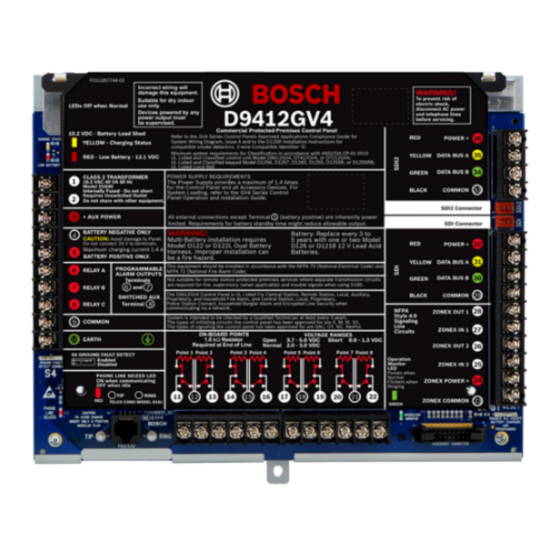
D9412GV4/D7412GV4/D7212GV4 | Installation and Operation Guide | 16.0 Faceplates 16.0 Faceplates 16.1 GV4 Series Faceplate Figure 33: D9412GV4/D7412GV4/D7212GV4 Faceplate Charging status LED (yellow) Ring Low battery LED (red) Operation monitor LED (green) Color-coded battery leads 10 - Accessory connector Ground fault detect enable... -
Page 76: Appendix A: System Wiring Diagrams
D9412GV4/D7412GV4/D7212GV4 | Installation and Operation Guide | Appendix A: System Wiring Diagrams Appendix A: System Wiring Diagrams Power Supply Side System Wiring Figure 34: D9412GV4/D7412GV4/D7212GV4 Power Supply Side System Wiring (Power and Phone) 1 - If required by local AHJ, connect D113 Battery 8 - Listed Audible Signaling Devices rated at Lead Supervision Module. -
Page 77: Input Points And Peripheral Devices Wiring Diagrams
D9412GV4/D7412GV4/D7212GV4 | Installation and Operation Guide | Appendix A: System Wiring Diagrams Input Points and Peripheral Devices Wiring Diagrams Figure 35: D9412GV4/D7412GV4/D7212GV4 Input Points and Peripheral Devices System Wiring 1 - (Optional): For 24 V applications use a UL 1481 5 - 1k Ω... -
Page 78: Sdi And Zonex Devices System Wiring
D9412GV4/D7412GV4/D7212GV4 | Installation and Operation Guide | Appendix A: System Wiring Diagrams SDI and Zonex Devices System Wiring System Wiring Figure 36: D9412GV4 SDI and Zonex Devices System Wiring System Wiring 1 - Up to 16 supervised D1255 (all versions), D1255RB, 5 - D8125 POPEX No.1... -
Page 79: Figure 37: D7412Gv4/D7212Gv4 Sdi And Zonex
D9412GV4/D7412GV4/D7212GV4 | Installation and Operation Guide | Appendix A: System Wiring Diagrams Figure 37: D7412GV4/D7212GV4 SDI and Zonex Devices System Wiring 1 - Up to 16 supervised D1255 (all versions), 5 - Up to two DX4020, ITS-DX4020-G, or B420 D1255RB, D1256, D1256RB Keypads, or... -
Page 80: Figure 38: D9412Gv4/D7412Gv4/D7212Gv4 Sdi2
D9412GV4/D7412GV4/D7212GV4 | Installation and Operation Guide | Appendix A: System Wiring Diagrams Figure 38: D9412GV4/D7412GV4/D7212GV4 SDI2 Devices System Wiring 1 - Up to 24 B208 Octo-input Modules 3 - Up to 2 B420 Ethernet Communication Modules 2 - Up to 12 B308 Octo-output Modules 4 - B820 SDI2 Inovonics Interface Module The D7412GV4 supports up to 7 Octo-inputs. -
Page 81: Appendix B: Point Address Charts
D9412GV4/D7412GV4/D7212GV4 | Installation and Operation Guide | Appendix B: Point Address Charts Appendix B: Point Address Charts Zonex 1 Points Place the labels on the base of the POPIT. Do not attach labels to the POPIT cover. A bullet ( ) in the switch column indicates that the switch is set to ON. -
Page 82: Zonex 2 Points
D9412GV4/D7412GV4/D7212GV4 | Installation and Operation Guide | Appendix B: Point Address Charts Zonex 2 Points Place the labels on the base of the POPIT. Do not attach labels to the POPIT cover. A number in the switch column indicates that the switch is set to ON. -
Page 83: Sdi2 Points
D9412GV4/D7412GV4/D7212GV4 | Installation and Operation Guide | Appendix B: Point Address Charts SDI2 Points Not all off-board points supported by the control panel can be supported on B208 Octo- input modules. Points 9 and 10, 19 and 20, etc. can be supported by ZONEX bus or SDI2 Wireless points. -
Page 84: Appendix C: Specifications
Current Control Panel: Idle 225 mA; Alarm 300 mA Requirements Refer to the Current Rating Chart for Standby Battery Calculations section in the D9412GV4/D7412GV4/D7212GV4 Approved Applications Compliance Guide (P/N: F01U201525) for the current draw requirements of other system components. Power All external connections are power-limited except battery terminals. -
Page 85: Terminal Wiring
D9412GV4/D7412GV4/D7212GV4 | Installation and Operation Guide | Appendix C: SpecificationsContents Terminal Wiring Table 31: Terminal Wiring Requirements Terminal Terminal Requirements Description 18 AWG min (up to 14 AWG max) 18 AWG min (up to 14 AWG max) + AUX POWER... - Page 86 SDI2 POWER Terminal accommodates 14 to 22 AWG, use appropriate wire size based on peripheral device current *D9412GV4 only. Terminals 25 and 26 are NOT USED on D7412GV4 and D7212GV4 Control Panels. Bosch Security Systems, Inc. | 3/12 | F01U266054-01...
- Page 87 D9412GV4/D7412GV4/D7212GV4 | Installation and Operation Guide | Appendix C: SpecificationsNotes Notes Bosch Security Systems, Inc. | 3/12 | F01U266054-01...
- Page 88 Bosch Security Systems, Inc. 130 Perinton Parkway Fairport, NY 14450 www.boschsecurity.com © Bosch Security Systems, Inc., 2012...