Sign In
Upload
Manuals
Brands
WAGO Manuals
Recording Equipment
MOVILINK SPEEDWAY 767
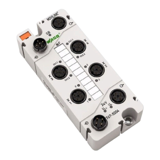
WAGO MOVILINK SPEEDWAY 767 Manuals
Manuals and User Guides for WAGO MOVILINK SPEEDWAY 767. We have
1
WAGO MOVILINK SPEEDWAY 767 manual available for free PDF download: Manual
WAGO MOVILINK SPEEDWAY 767 Manual (118 pages)
RS-232, RS-485, 2 interfaces 2 x M12 + 4 digital inputs/outputs 2 x M12, two inputs/outputs per connector
Brand:
WAGO
| Category:
Recording Equipment
| Size: 5.85 MB
Table of Contents
Table of Contents
5
Table of Contents
3
1 Notes about this Documentation
6
Validity of These Operating Instructions
6
Copyright
6
Symbols
7
Number Notation
9
Font Conventions
9
Table 1: Number Notation
9
Table 2: Font Conventions
9
2 Important Notes
10
Legal Bases
10
Subject to Changes
10
Personnel Qualification
10
Intended Use
11
Technical Condition of Specified Devices
11
Safety Advice (Precautions)
12
Safety Equipment
13
Notes on Operation
14
3 Device Description
15
Connectors
17
Figure 1: Connectors (Exemplary)
17
Table 3: Legend for Figure "Connectors
17
Marking Possibilities and Fastening
18
Figure 2: Marking Possibilities and Fastening (Exemplary)
18
Table 4: Legend for Figure "Marking Possibilities and Fastening
18
Display Elements
19
Figure 3: Display Elements (Exemplary)
19
Table 5: Legend for Figure "Display Elements
19
Labeling
20
Figure 4: Labeling
20
Table 6: Legend for Figure "Labeling
20
Figure 5: Label on the Module
21
Table 7: Description of Manufacturing Number
21
Schematic Diagram
22
Figure 6: Schematic Diagram
22
Dimensions
23
Figure 7: Dimensions of the Module in Millimeters (Exemplary)
23
Technical Data
24
Device Data
24
Supply
24
Communication
24
Table 8: Technical Data − Device
24
Table 9: Technical Data − Supply
24
Table 10: Technical Data − Communication
24
MOVILINK ® Interfaces
25
Digital Inputs
25
Input Characteristic
25
Table 11: Technical Data − MOVILINK ® Interfaces
25
Table 12: Technical Data − Digital Inputs
25
Table 13: Technical Data − Input Characteristic
25
Digital Outputs
26
Information for Actuator Selection
26
Table 14: Technical Data − Digital Outputs
26
Table 15: Technical Data − Actuator Selection
26
Effect of Operating State on Outputs
27
Configurable Functions of the MOVILINK ® Interfaces
27
Configurable Functions of the Digital Inputs/Outputs
27
Diagnostics
27
Table 16: Technical Data − Operating States
27
Table 17: Technical Data − Configurable Functions
27
Table 18: Technical Data − Configurable Functions of the Digital Inputs/Outputs
27
Table 19: Technical Data − Diagnostics
27
Process Image
28
Indicators
28
Isolation
28
Table 20: Technical Data − Process Image
28
Table 21: Technical Data − Indicators
28
Table 22: Technical Data − Isolation
28
Approvals
29
Standards and Guidelines
30
4 Mounting
31
Information on Mounting
31
Tools and Accessories Required for Mounting
33
Direct Mounting on Your System
34
Figure 8: Mounting the Module on a Grounded Frame or to
34
Mounting on a Carrier Rail (Only with WAGO Accessories)
35
Fastening the Carrier Rail Adapter to the Module
35
Figure 9: Fastening to the Carrier Rail Adapter
35
Fastening the Module with Carrier Rail Adapter to a Carrier Rail
36
Figure 10: Mounting the Carrier Rail Adapter (Exemplary)
36
Mounting on a Profile Rail (Only with WAGO Accessories)
37
Fastening the Profile Adapter to the Module
37
Figure 11: Fastening to the Profile Adapter
37
Fastening the Module with Profile Adapter to a Profile Rail
38
Marking and Replacing the Marking Spaces
39
Figure 12: Replacing the Marking Spaces
39
Mounting the Spacer in the Case of Compact Arrangement
40
Figure 13: Attaching a Spacer to a Module
40
Figure 14: Attaching Another Module with a Spacer
41
5 Connecting Data and Supply Cables
42
Notes
42
Required Accessories
43
Connecting the S-BUS Cables
44
Table 23: S-BUS Connection Assignment
44
Figure 15: S-BUS Connected to a Fieldbus Coupler and Modules
45
Connecting the Supply Cable
46
Table 24: Supply Connection Assignment
46
Figure 16: Supply Cable Connected to a Fieldbus Coupler and Modules
47
Connecting Interface Cables
48
Table 25: Serial Interfaces: Pin Assignment
48
Figure 17: Connectors of Interfaces
49
Connection Example
50
Figure 18: Connection Example 1 X MOVIMOT ® , RS-485 Mode
50
Connecting Sensor/Actuator Cables
51
Table 26: Digital Inputs and Outputs: Pin Assignment
51
Figure 19: Connectors of Sensors/Actuators
52
6 Commissioning
53
7 Parameterizing
54
Figure 20: Example of an Open DTM, Including Parameters
55
Table 27: DTM Buttons
55
Electronic Type Label
56
Table 28: Information on the Module
56
Diagnostic Overview
57
Figure 21: Example of the Diagnostic Overview of a Module (Information May Differ from the Actual Module)
57
Table 29: Diagnostics Setup
57
Table 30: Information about Existing Module Diagnostics
58
Table 31: Information about Existing Channel Diagnostics
58
Input and Output Parameters
59
Table 32: Overview of the Connection Mode
59
Connection Mode "Digital Output
60
Table 33: Overview of Adjustable Parameters for the Digital Outputs
60
Connection Mode "Digital Input
62
Table 34: Overview of Adjustable Parameters for the Digital Inputs
62
Parameters of the Interfaces
63
Operating Mode
63
Parameters of the Serial Interfaces
63
Parameters of the MOVILINK ® Interfaces
63
Table 35: Operating Mode
63
Table 36: Parameters of the Serial Interfaces
63
Table 37: Parameters of the MOVILINK ® Interfaces
63
Global Settings
64
Parameters of Field Supply
64
Table 38: Overview of Parameters for the Entire Module
64
Table 39: Overview of Adjustable Parameters for the Field Supply
64
Automatic Storage of System Parameters
65
Updating the Firmware
65
8 Process Image
66
Process Image in Easy Mode
67
Input Data in Easy Mode
67
Table 40: Fieldbus-Dependent PI Size
67
Table 41: Process Image - Input Data in Easy Mode
68
Output Data in Easy Mode
70
Table 42: Fieldbus-Dependent PI Size
70
Table 43: Process Image - Output Data in Easy Mode
72
Process Image in Mailbox 2.0 Mode
73
Input Data in Mailbox 2.0 Mode
73
Table 44: Fieldbus-Dependent PI Size
73
Table 45: Process Image - Input Data in Mailbox 2.0 Mode
74
Output Data in Mailbox 2.0 Mode
75
Table 46: Fieldbus-Dependent PI Size
75
Table 47: Process Image - Output Data in Mailbox 2.0 Mode
76
9 MOVILINK ® Interfaces
77
Function Block Simatic S7
77
Data Transfer
77
Data Transfer in Easy Mode
77
Data Transfer in Mailbox Mode
84
Movilink
84
Table 48: Supported Message Types
84
Message Type 6
85
Table 49: Message Type 6
85
Message Type 8
86
Table 50: Message Type 8
86
Message Type 9
88
Table 51: Message Type 9
88
Using Message Type 6
89
Figure 22: Compilation of MOVILINK ® Addresses for Type 6 Messages
89
Figure 23: Data Exchange between the PLC and Individual Slaves
90
Table 52: Data Exchange between the PLC and Individual Slaves
91
Figure 24: Data Exchange between the PLC and a Slave and Group
92
Table 53: Data Exchange between the PLC and a Slave and Group
92
9.2.2.1.5 Using Message Type 8 in Mailbox Mode
93
Figure 25: Compilation of MOVILINK ® Address for Type 8 Messages
93
Figure 26: Data Exchange between the PLC and Individual Slaves
94
Table 54: Data Exchange between the PLC and Individual Slaves
95
Figure 27: Data Exchange between the PLC and Individual Slaves with Throughput Optimization
97
Table 55: Data Exchange between the PLC and Individual Slaves with Throughput Optimization
98
10 Diagnostics
99
LED Signaling
99
Figure 28: Leds Indicating Operational Messages (Exemplary)
99
Table 56: Operating Messages 1
99
Table 57: Operational Messages 2
101
11 Service
102
Updating the Firmware
102
Replacing the Module
102
Disconnecting the Cables
102
Removing the Module from Your System
103
Removing the Module from the Carrier Rail
103
Figure 29: Removing the Module (with the Carrier Rail Adapter) from the Carrier Rail
103
Removing the Module from the Profile Adapter
104
Connecting the Module
104
Disposal
104
12 Appendix
105
Diagnostic Information
105
Table 58: Diagnostics of the Module
105
Table 59: Diagnostics of the Individual Channels of the Module
105
Mailbox 2.0 Transmission Method
106
Message
106
Figure 30: Communication Via Mailbox 2.0
106
Transmission Channel
107
Table 60: Structure of the Simple Header
107
Table 61: Structure of the Extended Header
107
The Handshake Byte
108
Figure 31: Use of the Handshake Byte
108
Table 62: Structure of the Handshake Byte
108
Table 65: Structure of the Handshake Byte
108
Communication Phases
109
Synchronization
109
12.2.3.1.1 Mailbox Commands
109
Table 63: Commands
109
12.2.3.1.2 Acknowledgement
110
12.2.3.1.3 Signaling
110
Table 64: Acknowledgement
110
Table 66: Signaling
110
12.2.3.1.4 Finite Automation
111
Figure 32: Finite Automation
111
Data Exchange
112
12.2.3.2.1 Example
113
Figure 33: Example of Send Operation
113
List of Figures
114
List of Tables
115
Advertisement
Advertisement
Related Products
WAGO Modular IO System INTERBUS S
WAGO 750-468
WAGO 750-468/000-001
WAGO 750-468/000-200
WAGO 750-468/025-000
WAGO 750-630
WAGO 750-630/040-001
WAGO 750-637/000-003
WAGO 750-637/040-001
WAGO 750-652
WAGO Categories
I/O Systems
Control Unit
Power Supply
Switch
Controller
More WAGO Manuals
Login
Sign In
OR
Sign in with Facebook
Sign in with Google
Upload manual
Upload from disk
Upload from URL