Sign In
Upload
Manuals
Brands
WAGO Manuals
I/O Systems
8FDI 24V PROFIsafe 750-662/000-004
WAGO 8FDI 24V PROFIsafe 750-662/000-004 Manuals
Manuals and User Guides for WAGO 8FDI 24V PROFIsafe 750-662/000-004. We have
2
WAGO 8FDI 24V PROFIsafe 750-662/000-004 manuals available for free PDF download: Manual
WAGO 8FDI 24V PROFIsafe 750-662/000-004 Manual (138 pages)
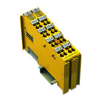
8FDI 24V PROFIsafe Safe 8-Channel Digital Input; 24 VDC; PROFIsafe
Brand:
WAGO
| Category:
I/O Systems
| Size: 4 MB
Table of Contents
Table of Contents
3
Validity of this Documentation
7
Copyright
7
Notes about this Documentation
7
Symbols
8
Number Notation
9
Font Conventions
9
Table 1: Number Notation
9
Table 2: Font Conventions
9
Personnel Qualifications
10
Use of the 750 Series in Compliance with Underlying Provisions
10
Subject to Changes
10
Legal Bases
10
Important Notes
10
Technical Condition of Specified Devices
11
Safety Advice (Precautions)
12
Device Description
16
View
18
Figure 1: View
18
Table 3: Legend for Figure "View
18
Connectors
19
Data Contacts/Local Bus
19
Figure 2: Data Contacts
19
Power Jumper Contacts/Field Supply
20
Figure 3: Power Jumper Contacts
20
Table 4: Legend for Figure "Power Jumper Contacts
20
Table 5: Legend for Figure "CAGE CLAMP ® Connections
22
Figure 4: CAGE CLAMP ® Connections
22
CAGE CLAMP ® Connectors
22
Display Elements
23
Figure 5: Indicators, Inputs 1
23
Table 6: Legend for Figure "Indicators, Inputs 1
23
Figure 6: Indicators, Inputs 5
24
Table 7: Legend for Figure "Indicators, Inputs 5
24
Figure 7: Communication/I/O Module Status Indicators
25
Table 8: Legend for Figure "Communication/I/O Module Status Indicators
25
Operating Elements
26
Figure 8: Coding Switch for the Profisafe Address (Set to 1018)
26
Schematic Diagrams
27
Input Block Diagram
27
Figure 9: Schematic Circuit Diagram
27
Figure 10: Input Block Diagram
27
Table 10: Technical Data - Power Supply Via Local Bus
28
Table 12: Technical Data - Communication
28
Table 11: Technical Data - Power Supply Via Power Jumper Contacts
28
Technical Data
28
Table 9: Technical Data - Device
28
Communication
28
Power Supply
28
Device Data
28
Digital Inputs
29
Digital Clock Outputs
29
Table 13: Technical Data - Digital Inputs
29
Table 14: Technical Data - Digital Clock Outputs
29
Safety Parameters
30
Single-Channel Safety Application, Duration of Use: 20 Years
30
Table 15: Safety Parameters for Single-Channel Safety Application - 20 Years
30
Table 16: Safety Parameters for Dual-Channel Safety Application - 20 Years
31
Dual-Channel Safety Application, Duration of Use: 20 Years
31
Connection Type
32
Climatic Environmental Conditions
32
Table 17: Technical Data - Field Wiring
32
Table 18: Technical Data - Power Jumper Contacts
32
Table 19: Technical Data - Data Contacts
32
Table 20: Technical Data - Climatic Environmental Conditions
32
Safety Response Time
33
Safety Response Time of the Digital Inputs
33
Safety Response Time of the Digital Inputs for Single-Channel Applications
33
Table 21: Safety Response Time of the Digital Inputs T(SR) in Ms in Single
33
Table 22: Safety Response Time of the Digital Inputs T(SR) in Ms in Dual
35
Safety Response Time of the Digital Inputs in Dual-Channel Applications
35
Approvals
36
Applications
37
Standards and Guidelines
38
Transport and Storage Conditions
39
Process Image
40
Profisafe Mode V2.4
40
Table 23: Process Image Profisafe Mode V2.4
40
Table 24: Process Image Profisafe Mode V2.6
41
Table 27: Profisafe Status Byte
41
Table 26: Input Channel Status Byte
41
Table 25: Input Process Value
41
Table 28: Profisafe Status Byte
41
Profisafe Status Byte
41
Profisafe-Modus V2.6
41
WAGO Status Byte
41
Input Process Value
41
Input Channel Status Byte
41
WAGO Control Byte
42
Profisafe Control Byte
42
Table 29: WAGO Control Byte
42
Table 30: Profisafe Control Byte
42
Mounting
43
Mounting Sequence
44
Inserting and Removing Devices
45
Inserting the I/O Module
45
Figure 11: Inserting I/O Module (Example)
45
Figure 12: Snap the I/O Module into Place (Example)
45
Removing the I/O Module
46
Figure 13: Removing the I/O Module (Example)
46
Figure 14: Connecting a Conductor to a CAGE CLAMP
47
Connect Devices
47
Connecting a Conductor to the CAGE CLAMP
47
Additional Information on the Power Supply
48
Disturbances in the Supply Voltage
49
Commissioning
50
Commissioning and Maintenance Instructions
50
Duration of Use
50
Adding or Replacing Components
51
Figure 15: Example of a Serial Number
51
Setting the Profisafe Address in the F I/O Module
52
Setting the Profisafe Address Using the Coding Switch
52
Setting the Profisafe Address Using the WAGO Parameterization Tool
52
Setting the Profisafe Address Via the GSD
53
Initial Assignment of a Profisafe Address Via the GSD
53
7.2.3.1.1 Checking the Profisafe Address Set Via the GSD
53
7.2.3.1.2 Confirmation of the Profisafe Address Set Via the GSD
54
Changing the Profisafe Address Set Via the GSD
55
Parameterization of the F I/O Module with the WAGO Parameterization Tool
56
Figure 16: Start View of WAGO Safety Editor (Example)
56
ONLINE Mode
57
Reading Iparameters from the Module or Parameter File
57
Writing Iparameters to the Module or Parameter File
57
OFFLINE Mode
58
Reading from a Parameter File
58
Writing to a Parameter File
59
Other Services for OFFLINE and ONLINE Mode
59
Comparing Iparameter Sets
59
Change Password
60
Description of the Call Options
60
Indirect Start Via WAGO-I/O-CHECK from the Engineering Tool of the Safe PLC (Module Level TCI Conformance Class 2)
61
Indirect Start Via WAGO-I/O-CHECK from the Engineering Tool of the Safe PLC (Device Level TCI Conformance Class 2)
61
Direct Start from the Operating System
61
Indirect Start Via WAGO-I/O-CHECK from the Operating System
61
Direct Start from the Engineering Tool of the Safe PLC (Module Level TCI Conformance Class 3 ONLINE)
62
Direct Start from the Engineering Tool of the Safe PLC (Device Level TCI OFFLINE)
62
Direct Start from the Engineering Tool of the Safe PLC (Module Level TCI OFFLINE)
62
Adjustable Parameters for Digital Inputs
62
Input Filter Time Parameter
63
Table 31: Adjustable Parameters for Digital Inputs
63
Short Circuit Test IX Parameter
64
Table 32: Assignment of Inputs to Clock Outputs
65
Table 33: Error Detection
65
Test Pulse Duration Parameter
66
Pre-Evaluation Parameter
66
Table 34: Equivalent Pre-Evaluation
67
Table 35: Antivalent Pre-Evaluation
68
Discrepancy Time IX and IX+1 Parameter
68
Table 36: Maximum Duration of a Deviation from the Valence Rule to Avoid
71
Table 37: Minimum Duration of a Deviation from the Valence Rule to Detect a
72
Restart Inhibit IX and IX+1 Parameter
73
Table 38: Required Signal States to Allow Acknowledgement When Restart Inhibit Is Activated
73
Operating Mode Parameter
74
Offline Parameterization of the F I/O Module with the Engineering Tool of the Safe PLC
75
Figure 17: Offline Parameterization - WAGO Safety Editor Start Screen
75
Figure 18: Offline Parameterization - "Crcs" Dialog in the WAGO Safety
77
Programming the Safe PLC
78
F I/O Module with Ipar Server
80
F I/O Module with Ipar Functionality from WAGO
80
F I/O Module Without Ipar Server
80
Connection Examples for Digital Inputs
82
Connection Examples
82
Emergency off Connection, Single-Channel
83
Figure 19: Connection 8 × Emergency Off, Single-Channel, Short Circuit Test
83
Figure 20: Connection 8 × Emergency Off, Single-Channel, Short Circuit Test
83
Emergency Stop Connection, Dual-Channel, Equivalent Pre-Evaluation
85
Figure 21: Connection 4 × Emergency-Off Switch, Dual Channel, Equivalent
85
Protective Door Monitoring Connection, Dual-Channel, Antivalent Pre-Evaluation
86
Figure 22: Connection 2 × Interlock Monitoring, Dual Channel, Antivalent Pre
86
Connection Example for Digital Inputs in "Rotary Table" Operating Mode (1 of N)
87
Figure 23: Connection 2 × Mode Selector Switch
87
Diagnostics
88
Error Detection
88
Errors and Error Types
89
Table 39: Errors and Error Types
89
Channel Pair Errors
90
Channel Errors
90
Behavior in Case of Error
90
Configuration/Communication Errors
91
Module Errors
91
Error Diagnostics
92
Table 40: Diagnostic Messages
92
Acknowledging Error Messages
99
Error Acknowledgment Profisafe V2.4
99
Figure 24: Schematic Representation of Acknowledgement in Profisafe
99
Error Acknowledgment Profisafe V2.6
100
Figure 25: Schematic Representation of Acknowledgement in Profisafe
100
Signal Sequence Diagrams
101
Figure26: Profisafe Mode V2.4 - Channel-Granular Passivation
101
Figure 27: Profisafe-Modus V2.6 - Signal Sequence: User
102
Figure 28: Profisafe-Modus V2.4 and V2.6 - Signal Sequence
102
Procedure
103
Service
103
Replacing the F I/O Module
103
F I/O Module with Ipar Server Functionality
104
Profisafe Address Set Using the Coding Switch
104
Profisafe Address Set Using the Parameterization Tool
104
F I/O Module Without Ipar Server Functionality
105
Profisafe Address Set Using the Coding Switch
105
Profisafe Address Set Using the Parameterization Tool
105
Firmware Update
106
Use in Hazardous Environments
108
Marking Configuration Examples
109
Marking for Europe According to ATEX and Iecex
109
Figure 29: Marking Example Per ATEX and Iecex
109
Figure 30: Text Detail - Marking Example Per ATEX and Iecex
109
Table 41: Description of the Marking Example Per ATEX and Iecex
110
Figure 31: Marking Example of an Approved I/O Module Ex I Per ATEX and
111
Figure 32: Text Detail - Marking Example of an Approved I/O Module Ex I Per ATEX and Iecex
111
Table 42: Description of the Marking Example of an Approved I/O Module Ex I Per ATEX and Iecex
112
Marking for the United States of America (NEC) and Canada (CEC)
113
Figure 33: Marking Example According to NEC
113
Figure 34: Text Detail - Marking Example According to NEC 500
113
Table 43: Description of Marking Example According to NEC 500
113
Figure 35: Text Detail - Marking Example for Approved I/O Module Ex I
114
Figure 36: Text Detail - Marking Example for Approved I/O Module Ex I
114
Table 44: Description of Marking Example for Approved I/O Module Ex I
114
Table 45: Description of Marking Example for Approved I/O Module Ex I
114
Figure 37: Text Detail - Marking Example for Approved I/O Module Ex I
115
Table 46: Description of Marking Example for Approved I/O Module Ex I
115
Special Notes Including Explosion Protection
116
Installation Regulations
116
Special Notes Regarding UL Hazardous Location
118
Appendix
119
Profisafe
119
Figure 38: Mixed Operation of Safety-Related and Non-Safety-Related I/O
119
Figure 39: Profisafe Layer Model
120
Iparameters (Individual Parameters)
121
Figure 40: Ipar Server
121
Overview of Profisafe F Parameters
122
Table 47: Legend for the Ipar Server Figure
122
Table 48: Profisafe F Parameters
122
Glossary
126
List of Figures
134
List of Tables
136
Advertisement
WAGO 8FDI 24V PROFIsafe 750-662/000-004 Manual (128 pages)
Brand:
WAGO
| Category:
I/O Systems
| Size: 4 MB
Table of Contents
Table of Contents
3
Notes about this Documentation
7
Validity of this Documentation
7
Copyright
7
Symbols
8
Number Notation
9
Font Conventions
9
Table 1: Number Notation
9
Table 2: Font Conventions
9
Important Notes
10
Legal Bases
10
Subject to Changes
10
Personnel Qualifications
10
Use of the 750 Series in Compliance with Underlying Provisions
10
Technical Condition of Specified Devices
11
Safety Advice (Precautions)
12
Device Description
16
View
18
Figure 1: View
18
Table 3: Legend for Figure "View
18
Connectors
19
Data Contacts/Local Bus
19
Figure 2: Data Contacts
19
Power Jumper Contacts/Field Supply
20
Figure 3: Power Jumper Contacts
20
Table 4: Legend for Figure "Power Jumper Contacts
20
CAGE CLAMP ® Connectors
22
Figure 4: CAGE CLAMP ® Connections
22
Table 5: Legend for Figure "CAGE CLAMP ® Connections
22
Display Elements
23
Figure 5: Indicators, Inputs 1
23
Table 6: Legend for Figure "Indicators, Inputs 1
23
Figure 6: Indicators, Inputs 5
24
Table 7: Legend for Figure "Indicators, Inputs 5
24
Figure 7: Communication/I/O Module Status Indicators
25
Table 8: Legend for Figure "Communication/I/O Module Status Indicators
25
Operating Elements
26
Figure 8: Coding Switch for the Profisafe Address (Set to 1018)
26
Schematic Diagrams
27
Input Block Diagram
27
Figure 9: Schematic Circuit Diagram
27
Figure 10: Input Block Diagram
27
Technical Data
28
Device Data
28
Power Supply
28
Communication
28
Table 9: Technical Data - Device
28
Table 10: Technical Data - Power Supply Via Local Bus
28
Table 11: Technical Data - Power Supply Via Power Jumper Contacts
28
Table 12: Technical Data - Communication
28
Digital Inputs
29
Digital Clock Outputs
29
Table 13: Technical Data - Digital Inputs
29
Table 14: Technical Data - Digital Clock Outputs
29
Safety Parameters
30
Single-Channel Safety Application, Duration of Use: 20 Years
30
Table 15: Safety Parameters for Single-Channel Safety Application - 20 Years
30
Dual-Channel Safety Application, Duration of Use: 20 Years
31
Table 16: Safety Parameters for Dual-Channel Safety Application - 20 Years
31
Connection Type
32
Climatic Environmental Conditions
32
Table 17: Technical Data - Field Wiring
32
Table 18: Technical Data - Power Jumper Contacts
32
Table 19: Technical Data - Data Contacts
32
Table 20: Technical Data - Climatic Environmental Conditions
32
Safety Response Time
33
Safety Response Time of the Digital Inputs
33
Safety Response Time of the Digital Inputs for Single-Channel Applications
33
Table 21: Safety Response Time of the Digital Inputs T(SR) in Ms in Single
33
Safety Response Time of the Digital Inputs in Dual-Channel Applications
35
Table 22: Safety Response Time of the Digital Inputs T(SR) in Ms in Dual
35
Approvals
36
Applications
37
Standards and Guidelines
38
Transport and Storage Conditions
39
Process Image
40
Table 23: Profisafe Process Image
40
Table 24: Input Process Value
40
Table 25: Input Channel Status Byte
40
Table 26: Profisafe Status Byte
40
Table 27: Profisafe Control Byte
40
Mounting
42
Mounting Sequence
43
Inserting and Removing Devices
44
Inserting the I/O Module
44
Figure 11: Inserting I/O Module (Example)
44
Figure 12: Snap the I/O Module into Place (Example)
44
Removing the I/O Module
45
Figure 13: Removing the I/O Module (Example)
45
Connect Devices
46
Connecting a Conductor to the CAGE CLAMP
46
Figure 14: Connecting a Conductor to a CAGE CLAMP
46
Additional Information on the Power Supply
47
Disturbances in the Supply Voltage
47
Commissioning
48
Commissioning and Maintenance Instructions
48
Duration of Use
48
Figure 15: Example of a Serial Number
48
Adding or Replacing Components
49
Setting the Profisafe Address
50
Setting the Profisafe Address Using the Coding Switch
50
Setting the Profisafe Address Using the WAGO Parameterization Tool
51
Parameterization of the F I/O Module with the WAGO Parameterization Tool
51
ONLINE Mode
52
Reading Iparameters from the Module or Parameter File
52
Figure 16: Start View of WAGO Safety Editor
52
S Writing Iparameters to the Module or Parameter File
53
OFFLINE Mode
54
Reading from a Parameter File
54
Writing to a Parameter File
54
Other Services for OFFLINE and ONLINE Mode
55
Comparing Iparameter Sets
55
Change Password
55
Description of the Call Options
56
Indirect Start Via WAGO-I/O-CHECK from the Operating System
56
Direct Start from the Operating System
57
Indirect Start Via WAGO-I/O-CHECK from the Configuration Program (Device Level TCI Conformance Class 2)
57
Indirect Start Via WAGO-I/O-CHECK from the Configuration Program (Module Level TCI Conformance Class 2)
57
Direct Start from the Configuration Program (Module Level TCI Conformance Class 3 ONLINE)
57
Direct Start from the Configuration Program (Device Level TCI OFFLINE)
57
Direct Start from the Configuration Program (Module Level TCI OFFLINE)
58
Adjustable Parameters for Digital Inputs
58
Table 28: Adjustable Parameters for Digital Inputs
58
Input Filter Time Parameter
59
Short Circuit Test IX Parameter
60
Table 29: Assignment of Inputs to Clock Outputs
60
Table 30: Error Detection
61
Test Pulse Duration Parameter
62
Pre-Evaluation Parameter
62
Table 31: Equivalent Pre-Evaluation
63
Discrepancy Time IX and IX+1 Parameter
64
Table 32: Antivalent Pre-Evaluation
64
Table 33: Maximum Duration of a Deviation from the Valence Rule to Avoid
67
Table 34: Minimum Duration of a Deviation from the Valence Rule to Detect a
68
Restart Inhibit IX and IX+1 Parameter
69
Table 35: Required Signal States to Allow Acknowledgement When Restart Inhibit Is Activated
69
Operating Mode Parameter
70
Programming the Safe PLC
71
F I/O Module with Ipar Server
73
F I/O Module with Ipar Functionality from WAGO
73
F I/O Module Without Ipar Server
73
Connection Examples
74
Connection Examples for Digital Inputs
74
Emergency off Connection, Single-Channel
75
Figure 17: Connection 8 × Emergency Off, Single-Channel, Short Circuit Test
75
Figure 18: Connection 8 × Emergency Off, Single-Channel, Short Circuit Test
75
Emergency Stop Connection, Dual-Channel, Equivalent Pre-Evaluation
77
Figure 19: Connection 4 × Emergency-Off Switch, Dual Channel, Equivalent
77
Protective Door Monitoring Connection, Dual-Channel, Antivalent Pre-Evaluation
78
Figure 20: Connection 2 × Interlock Monitoring, Dual Channel, Antivalent Pre
78
Connection Example for Digital Inputs in "Rotary Table" Operating Mode (1 of N)
79
Figure 21: Connection 2 × Mode Selector Switch
79
Diagnostics
80
Error Detection
80
Errors and Error Types
81
Table 36: Errors and Error Types
81
Behavior in Case of Error
82
Channel Errors
82
Channel Pair Errors
82
Module Errors
83
Configuration/Communication Errors
83
Error Diagnostics
84
Table 37: Diagnostic Messages
84
Acknowledging Error Messages
91
Error Acknowledgment
91
Figure 22: Schematic Representation of Acknowledgement
91
Signal Sequence Diagramms
93
Figure 23: Signal Sequence: User Acknowledgement of Channel Error
93
Figure 24: Signal Sequence: Communication Error
93
Service
94
Replacing the F I/O Module
94
Procedure
94
F I/O Module with Ipar Server Functionality
95
Profisafe Address Set Using the Coding Switch
95
Profisafe Address Set Using the Parameterization Tool
95
F I/O Module Without Ipar Server Functionality
96
Profisafe Address Set Using the Coding Switch
96
Profisafe Address Set Using the Parameterization Tool
96
Firmware Update
97
Use in Hazardous Environments
99
Marking Configuration Examples
100
Marking for Europe According to ATEX and Iecex
100
Figure 25: Marking Example Per ATEX and Iecex
100
Figure 26: Text Detail - Marking Example Per ATEX and Iecex
100
Table 38: Description of the Marking Example Per ATEX and Iecex
101
Figure 27: Marking Example of an Approved I/O Module Ex I Per ATEX and
102
Figure 28: Text Detail - Marking Example of an Approved I/O Module Ex I Per ATEX and Iecex
102
Table 39: Description of the Marking Example of an Approved I/O Module Ex I Per ATEX and Iecex
103
Marking for the United States of America (NEC) and Canada (CEC)
104
Figure 29: Marking Example According to NEC
104
Figure 30: Text Detail - Marking Example According to NEC 500
104
Table 40: Description of Marking Example According to NEC 500
104
Figure 31: Text Detail - Marking Example for Approved I/O Module Ex I
105
Figure 32: Text Detail - Marking Example for Approved I/O Module Ex I
105
Table 41: Description of Marking Example for Approved I/O Module Ex I
105
Table 42: Description of Marking Example for Approved I/O Module Ex I
105
Figure 33: Text Detail - Marking Example for Approved I/O Module Ex I
106
Table 43: Description of Marking Example for Approved I/O Module Ex I
106
Installation Regulations
107
Special Notes Including Explosion Protection
107
Special Notes Regarding UL Hazardous Location
109
Appendix
110
Profisafe
110
Figure 34: Mixed Operation of Safety-Related and Non-Safety-Related I/O
110
Figure 35: Profisafe Layer Model
111
Individual Parameters (Iparameters)
112
Figure 36: Ipar Server
112
Overview of Profisafe F Parameters
113
Table 44: Legend for the Ipar Server Figure
113
Table 45: Profisafe F Parameters
113
Profisafe Certificates
116
Glossary
117
List of Figures
125
List of Tables
126
Advertisement
Related Products
WAGO 750-666/000-004
WAGO 750-650/000-010
WAGO 750-650/000-011
WAGO 750-650/000-013
WAGO 750-650/000-016
WAGO 750-644
WAGO 750-613/040-000
WAGO 750-653
WAGO 750-653/000-001
WAGO 750-630/000-004
WAGO Categories
I/O Systems
Control Unit
Power Supply
Switch
Controller
More WAGO Manuals
Login
Sign In
OR
Sign in with Facebook
Sign in with Google
Upload manual
Upload from disk
Upload from URL