Sign In
Upload
Manuals
Brands
WAGO Manuals
I/O Systems
750-677
WAGO 750-677 Pulse Width Output Manuals
Manuals and User Guides for WAGO 750-677 Pulse Width Output. We have
1
WAGO 750-677 Pulse Width Output manual available for free PDF download: Manual
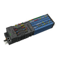
WAGO 750-677 Manual (108 pages)
4PWM 24 VDC 0.2A XTR 4 Pulse Width Outputs; 24 VDC; 0.2 A; 20 kHz; Extreme
Brand:
WAGO
| Category:
I/O Systems
| Size: 4.56 MB
Table of Contents
Table of Contents
3
Copyright
6
Notes about this Documentation
6
Validity of this Documentation
6
Symbols
7
Number Notation
9
Font Conventions
9
Table 1: Number Notation
9
Table 2: Font Conventions
9
Personnel Qualifications
10
Use of the 750 Series in Compliance with Underlying Provisions
10
Subject to Changes
10
Legal Bases
10
Important Notes
10
Technical Condition of Specified Devices
11
2.1.4.1.1 Electrical and Electronic Equipment
11
Disposal
11
2.1.4.1.2 Packaging
12
Safety Advice (Precautions)
13
Device Description
17
View
19
Figure 1: View
19
Table 3: Legend for Figure "View
19
Connectors
20
Data Contacts/Local Bus
20
Figure 2: Data Contacts
20
Table 4: Legend for Figure "Power Jumper Contacts
21
Power Jumper Contacts/Field Supply
21
Figure 3: Power Jumper Contacts
21
Cage Clamp
22
Figure 4: CAGE CLAMP ® Connectors
22
Table 5: Legend for Figure "CAGE CLAMP ® Connectors
22
Display Elements
24
Figure 5: Display Elements
24
Table 6: Legend for Figure "Display Elements
24
Schematic Diagram
25
Figure 6: Schematic Diagram
25
Table 8: Technical Data - Power Supply
26
Table 7: Technical Data - Device
26
Power Supply
26
Device Data
26
Technical Data
26
Table 9: Technical Data − Outputs
27
Connection Type
28
Mechanical Conditions
28
Climatic Environmental Conditions
28
Table 10: Technical Data - Field Wiring
28
Table 11: Technical Data - Power Jumper Contacts
28
Table 12: Technical Data - Data Contacts
28
Table 13: Technical Data - Mechanical Conditions
28
Table 14: Technical Data - Climatic Environmental Conditions
28
Approvals
29
Table 15: Standards and Rated Conditions for Explosion Protection Applications
31
Standards and Guidelines
31
Table 16: Climatic and Mechanical Environmental Conditions and
32
Table 17: EMC - Product- and Generic Standards
33
Table 18: EMC - Testing Standards: Immunity to Interference
34
Table 19: Emc - Testing Standards: Emission of Interference
36
Table 20: Standards and Rated Conditions for Rail Applications
38
Table 21: Further EMC Requirements for Railroad Applications
38
Notes and Limitations on Areas of Application
39
Power Plants and Voltage Substations
39
Residential Applications
39
Figure 7: Diagram for Determining the Cable Length in Residential
39
Figure 8: Diagram for Determining the Max. Cable Lengths in Marine
40
Marine Applications
40
Table 22: WAGO Power Supplies for Field Supply in Marine Applications
41
Process Image
42
Operating Modes
43
Pwm DC
43
Process Image
44
Table 23: Process Image (PWM DC)
44
Table 24: Control Byte 0 (PWM DC)
44
Table 25: Control Byte 2 (PWM DC)
44
Parameter Settings
45
Function of the Output Channels
45
Table 26: Status Byte 0 (PWM DC)
45
Table 27: Status Byte 2 (PWM DC)
45
Table 28: Process Values (PWM DC)
46
Process Values
46
PWM Frq
47
Process Image
47
Table 29: Process Image (PWM Frq)
47
Table 30: Control Byte 0 (PWM Frq)
47
Table 31: Control Byte 2 (PWM Frq)
48
Table 32: Status Byte 0 (PWM Frq)
48
Table 33: Status Byte 2 (PWM Frq)
48
Parameter Settings
49
Function of the Output Channels
49
Process Values
49
Table 34: Process Values (PWM Frq)
49
Table 35: Process Image (PWM Frq-Cnt)
50
Process Image
50
PWM Frq-Cnt
50
Table 36: Control Byte 0 (PWM Frq-Cnt)
51
Table 37: Control Byte 2 (PWM Frq-Cnt)
51
Parameter Settings
52
Table 38: Status Byte 0 (PWM Frq-Cnt)
52
Table 39: Status Byte 2 (PWM Frq-Cnt)
52
Function of the Output Channels
53
Process Values (PWM Frq-Cnt)
53
Table 40: Process Values (PWM Frq-Cnt)
53
Pulse Frq-Cnt
54
Process Image
54
Table 41: Process Image (Pulse Frq-Cnt)
54
Table 44: Status Byte 0 (Pulse Frq-Cnt)
55
Table 43: Control Byte 2 (Pulse Frq-Cnt)
55
Table 42: Control Byte 0 (Pulse Frq-Cnt)
55
Table 62: Status Byte 0
56
Parameter Settings
56
Table 45: Status Byte 2 (Pulse Frq-Cnt)
56
Function of the Output Channels
57
Process Values (Pulse Frq-Cnt)
57
Table 46: Process Values (Pulse Frq-Cnt)
57
PWM Pulse-Dir
58
Process Image
59
Table 47: Process Image (PWM Pulse-Dir)
59
Table 48: Control Byte 0 (PWM Pulse-Dir)
59
Table 49: Control Byte 2 (PWM Pulse-Dir)
59
Table 51: Status Byte 2 (PWM Pulse-Dir)
60
Table 50: Status Byte 0 (PWM Pulse-Dir)
60
Function of the Output Channels
61
Process Values
61
Table 63: Status Byte 2
61
Parameter Settings
61
Table 52: Process Values (PWM Pulse-Dir)
62
Functions
63
Mounting
64
Mounting Sequence
64
Inserting and Removing Devices
65
Inserting the I/O Module
65
Figure 9: Inserting I/O Module (Example)
65
Figure 11: Removing the I/O Module (Example)
66
Removing the I/O Module
66
Figure 10: Snap the I/O Module into Place (Example)
66
Connecting a Conductor to the CAGE CLAMP
67
Figure 12: Connecting a Conductor to a CAGE CLAMP
67
Connect Devices
67
Connection Examples
68
Figure 13: Connection Example 1
68
Figure 14: Example 2 ─ All Channels with Non-Inverted Configured Output
69
Figure 15: Example 3 ─ All Channels with Inverted Configured Output
69
Figure 16: Example 4 ─ Bridge Mode Channel Pair 1&2 When Wiring the Load
70
Start Via WAGO-I/O-CHECK
71
Figure 17: Starting the Parameterization Dialog from WAGO-I/O-CHECK
71
Configuration and Parameterization with WAGO Software Tools
71
Commissioning
71
Via E!Cockpit Starten
72
Figure 18: Scan Nodes (Example)
72
Figure 19: Apply the Network View (Example)
73
Figure 20: Open Device View (Example)
73
Figure 21: Module Settings (Example)
73
Parameterization Dialog
74
Figure 23: Parameterization Dialog
74
Table 53: Legend for Figure "Parameterization Dialog
74
General Settings
75
Table 54: Buttons
75
Table 55: Navigation Via the Menu
75
Table 56: 750-677, "Common" Menu Item
76
Figure 24: 750-677, "General" Menu Item
76
Settings of the Channel Pairs
76
Table 57: 750-677, "Channel X & Y" Menu Item
77
Figure 25: 750-677, "Channels X & Y" Menu Item, Selecting the Operating
79
Figure 26: 750-677, "Channels X & Y" Menu Item, Selecting the Operating
80
Figure 27: 750-677, "Channels X & Y" Menu Item, Selecting the Operating
80
Figure 28: 750-677, "Channels X & Y" Menu Item, Selecting the Operating Mode (Example 4)
80
IO Test
81
Data Dialog
81
Figure 30: Data Dialog (Sample Excerpt)
81
Table 58: Data Dialog Legend
81
Figure 31: Data Dialog, Example 1
82
Figure 32: Data Dialog, Example 2
83
Figure 34: Context Menu
84
Figure 33: Data Dialog, Example 3
84
Figure 35: Data Dialog, Example 4
85
Configuration and Parameterization Via GSD File
86
Configuration 750-677/040-000 (4PWM 24 VDC 0.2A XTR)
86
Fieldbus Coupler PROFIBUS DP 750-333/040-000
86
Parameterization 750-677/040-000 (4PWM 24 VDC 0.2A XTR)
86
Table 59: PROFIBUS DP Configuration
86
Table 60: Device-Specific Parameters
87
Diagnostics
88
Behavior of the I/O Module in the Event of an Error
88
Diagnostics Via Status Byte
88
Table 61: Prioritization of Status Information
88
Table 66: Signal Evaluation - Channel LED "C
89
Table 67: Signal Evaluation - Channel LED "G
89
Table 64: Signal Evaluation - Status LED "A
89
Table 65: Signal Evaluation - Error LED "E
89
Diagnostics Via Indicators
89
Use in Hazardous Environments
90
Marking Configuration Examples
91
Marking for Europe According to ATEX and Iecex
91
Figure 37: Marking Example Per ATEX and Iecex
91
Figure 38: Text Detail - Marking Example Per ATEX and Iecex
91
Table 68: Description of the Marking Example Per ATEX and Iecex
92
Figure 39: Marking Example of an Approved I/O Module Ex I Per ATEX and Iecex
93
Figure 40: Text Detail - Marking Example of an Approved I/O Module Ex I Per ATEX and Iecex
93
Table 69: Description of the Marking Example of an Approved I/O Module Ex I Per ATEX and Iecex
94
Table 70: Description of Marking Example According to NEC 500
95
Marking for the United States of America (NEC) and Canada (CEC)
95
Table 71: Description of Marking Example for Approved I/O Module Ex I
96
Table 72: Description of Marking Example for Approved I/O Module Ex I
96
Table 73: Description of Marking Example for Approved I/O Module Ex I
97
Installation Regulations
98
Special Notes Including Explosion Protection
98
Special Notes Regarding UL Hazardous Location
100
Service
101
Factory Setting (Default Values)
101
Firmware Update/Downgrade
101
Table 74: Factory Settings - Default Values
101
List of Figures
103
List of Tables
105
Advertisement
Advertisement
Related Products
WAGO 750-677/040-000
WAGO 750-650/000-002
WAGO 750-650/000-015
WAGO 750-624/040-001
WAGO I/O-SYSTEM 750-613
WAGO 750-630/000-005
WAGO 750-630/000-012
WAGO 750-641
WAGO 750-630/000-007
WAGO 750-655
WAGO Categories
I/O Systems
Control Unit
Power Supply
Switch
Controller
More WAGO Manuals
Login
Sign In
OR
Sign in with Facebook
Sign in with Google
Upload manual
Upload from disk
Upload from URL