Sign In
Upload
Manuals
Brands
Thermal Solutions Manuals
Boiler
Arctic 5500
Thermal Solutions Arctic 5500 Manuals
Manuals and User Guides for Thermal Solutions Arctic 5500. We have
2
Thermal Solutions Arctic 5500 manuals available for free PDF download: Installation & Operation Manual
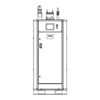
Thermal Solutions Arctic 5500 Installation & Operation Manual (100 pages)
Brand:
Thermal Solutions
| Category:
Boiler
| Size: 13.28 MB
Table of Contents
Table of Contents
2
Introduction
5
Important Information
5
Disclaimers and Local Codes
5
Test and Inspections
6
Component Description
6
Table 1: Water Flow Switch Settings
6
Figure 1: Arctic 1000 External Boiler Connections
7
Figure 2: Arctic 1500-3000 External Boiler
7
Connections
7
Figure 3: Arctic 3500-6000 External Boiler Connections
7
Installation Conformance
8
Boiler Foundation
8
Clearance and Serviceability
8
Ambient Boiler Room Temperatures
8
Pre-Installation
8
Figure 4: Clearances and Serviceability
9
Table 2: Clearances and Serviceability
9
Boiler Water and Condensate Connections
10
Installation
10
Condensate Trap/Drain Assembly
11
Figure 5: Condensate Drain Trap
11
Figure 6: Condensate Assembly Orientation
11
Table 3: Typical Condensate Flow Rate
11
Gas Supply Connections
12
Venting
15
Field Installation
16
Venting Design Requirements
16
Table 4: Vent and Combustion Air Pipe Diameters
17
Table 5: Vent and Combustion Air Equivalent Length
17
Table 6: Vent Air Pressure Drop Data
18
Table 7: Combustion Air Pressure Drop Data
19
Table 8: Combustion Air and Flue Gas Requirements
20
Table 9: Approved Vent Manufacturers and
20
Table 10: Stainless Steel and CPVC Vent Adapters
20
Table 11: Polypropylene Vent Adapters
21
Table 12: Stainless Steel Vent and Intake
21
Table 13: Polypropylene Vent and Intake
21
Table 14: Recommended Venting Configurations
22
General Termination
23
Figure 7: Vent Terminal Clearances
24
Table 15: Other than Direct Vent Terminal
25
Table 16: Table of Acceptable Terminations
26
Vent and Combustion Air Terminations
27
Figure 8: Horizontal Sidewall Termination
28
Figure 9: Slopped Roof Termination
28
Multiple Appliance Terminations
29
Figure 10: Flat Roof Vent Terminations
29
Terminal Installation
30
Figure 11: Multiple Appliance Direct Vent
31
Termination
31
Polypropylene Venting
32
Optional Room Air for Combustion
32
Figure 12: Flexible Vent in Masonry Chimney with
35
Massachusetts
36
Requirements
38
Table 17: Electrical Requirements
38
Gas Supply Requirements
39
Sound Pressure Levels
39
Table 18: Gas Supply Requirements
39
Table 19: Sound Pressure Levels
39
Table 22: Water Flow Rates for Primary/Secondary
40
Table 23: Water Flow Rates for Primary/Secondary
40
Table 20: Minimum Water Flow Rates for Variable
40
Table 21: Maximum Water Flow Rate for Variable
40
Boiler out Procedure
41
Before Operation
41
Table 24: Water Flow Rates for Constant Volume
41
Table 25: GPM Increase for Glycol System
41
Replacement Boiler Installations
42
Draining and Refilling the Boiler & System
42
Table 26: Chemical Agents and Effects
43
System Start-Up
44
Table 27: Recommended Feed Water Limits
44
System Check
45
Power the Boiler
45
Figure 13: Dungs Valve
47
Figure 14: Siemens Valves
47
Table 28: Siemens Nominal Low Fire
47
Finish Commissioning the Arctic 1000 - 6000
49
Table 29: Safety Device Tests
50
Service, Maintenance, and Inspection
51
Figure 15: Arctic 1000-3000 Ignition Assembly
52
Figure 16: Arctic 3500-6000 Ignition Assembly
53
Figure 17: Panel Removal in Preparation for Tube
54
Figure 18: Panel Removal in Preparation for Tube
54
Figure 19: Panel Removal in Preparation for Tube
55
Figure 20: Tube Puller Insertion
56
Table 30: Safety and Operating Controls
58
Table 31: General Troubleshooting
59
Appendix A: Sizing Gas Piping
60
Table 32: Maximum Gas Capacity of Schedule
60
Table 33: Equivalent Lengths of Standard Pipe
61
Table 34: Specific Gravity Correction Factors
61
Appendix B: Air Switch Adjustment Arctic 1500-6000
62
Appendix C: Venting Diagrams
63
Figure 21: Typical Horizontal Vent Piping
63
Figure 22: Typical Vertical Pressurized Venting
63
Appendix D: Combustion Air Diagrams
64
Figure 23: Typical Horizontal Air Intake Piping
64
Figure 24: Typical Vertical Air Intake Piping
64
Appendix E: Boiler Piping Diagrams
65
Figure 25: Single Boiler, Primary / Secondary
65
Figure 26: Multiple Boilers, Primary Reverse-Return
66
Figure 27: Multiple Boilers, Primary / Secondary
67
Figure 28: Multiple Boilers, Primary / Secondary
68
Figure 29: Multiple Boilers, Primary / Secondary
69
Appendix F: Water Flow Pressure Drops
70
Appendix G: Wiring Diagrams
72
Figure 30: Arctic 1000 Wiring Diagram
72
Figure 31: Arctic 1500 to Arctic 3000 115 VAC Single
74
Figure 32: Arctic 1500 to Arctic 3000 208 - 230 VAC
76
Figure 33: Arctic 2000 to Arctic 3000 208-460 VAC
78
Three Phase Wiring Diagram
78
Figure 34: Arctic 1500 to Arctic 3000 High Turndown
80
VAC Single or
80
Figure 35: Arctic 1500 to Arctic 3000 Dual Fuel
84
Figure 36: Arctic 3500 to Arctic 6000 208-460 VAC
88
Figure 37: Arctic 3500 to Arctic 6000 Dual Fuel 208-460 VAC Three Phase Wiring Diagram
92
Appendix H: Thermal Solutions (Seller) Limited Warranty
97
Appendix I: Installation & Startup Report
98
Advertisement
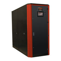
Thermal Solutions Arctic 5500 Installation & Operation Manual (74 pages)
CONDENSING BOILER
Brand:
Thermal Solutions
| Category:
Boiler
| Size: 6.6 MB
Table of Contents
Table of Contents
2
1 Introduction
6
Disclaimers and Local Codes
6
Important Information
6
Component Description
7
Table 1 Water Flow Switch Settings
7
Test and Inspections
7
Figure 2: ARC1500 - 3000 External Boiler Connections and Components
8
2 Pre-Installation
9
Installation Conformance
9
Boiler Foundation
9
Clearances and Serviceability
9
Figure 3: ARC3500-6000 External Boiler Connections and Components
9
Figure4: Clearances and Serviceability
10
Flow Connection
11
3 Installation
11
Receiving the Boiler
11
Boiler Connections
11
Safety Relief Valves
11
Table 2: Clearances and Serviceability
11
Condensate Drain Connection
12
ARC1000 Condensate Drain Trap
12
Table 3: Typical Condensate Flow Rate
12
ARC1500 - 6000 Condensate Drain Trap
13
Drain Connection
12
Expansion Tank Connections
12
Minimum Relief Valve Settings
12
Gas Supply Connection
13
Drip Leg
13
Gas Piping Leak Test
13
Figure5: ARC 1000 Condensate Drain Trap
13
Venting of Gas Train Components
14
Combustion Air Supply System
14
Combustion Air Openings
14
Two Permanent Opening Method
14
One Permanent Opening Method
15
Mechanical Air Supply Systems
15
Louvers, Grilles, and Screens
15
Louvers and Grilles
15
Screens
15
Motorized Louvers
15
Combustion Air Ducts
16
Ducted Combustion Air
16
Venting Requirements
16
Category II Venting
18
Massachusetts
19
Table 4: Combustion Air and Flue Gas Requirements
19
Combustion Air and Venting Requirements for Canada
21
Air Supply Requirements Per CAN/CSA-B149.1-05 for Appliances Having an Input
21
Exceeding 400 MBH
21
Combustion Air Supply Dampers, Louvers, and Grilles
21
Mechanical Combustion Air Supply
22
Appliance Venting Per CAN/CSA-B149.1-05
22
Requirements
22
Electrical
22
Gas Supply Requirements
23
Table 5: Electrical Requirements
23
Pump and Piping Requirements
24
Water Flow Rates (Variable Primary Pumping Systems)
24
Table 6: Gas Supply Requirements
24
Table 7 Sound Pressure Levels
24
Water Flow Rates (Primary / Secondary Systems)
25
Table 8 Minimum Water Flow Rates for Variable Primary Pumping
25
Table 9 Maximum Water Flow Rates for Variable Primary Pumping
25
Table 10 Water Flow Rates for Primary / Secondary Pumping 20F ΔT
25
Water Flow Rates (Constant Volume Primary Pumping Systems)
26
Water Flow Rates for Glycol
26
Before Placing Boiler in Operation
26
Sound Pressure Levels
24
Pre-Boil out Flushing of System
26
Table 11 Water Flow Rates for Primary / Secondary Pumping 40F ΔT
26
Table 12: Water Flow Rates for Constant Volume Primary Pumping
26
Table 13 GPM Increase for Glycol Systems
26
Boil out Procedure
27
Replacement Boiler Installations
27
Draining and Refilling the Boiler & System
28
Filling the System
28
Hydrostatic Test of Boilers and System
28
Boiler Water Treatment
28
Purpose of Water Treatment
28
Continuous Monitoring
29
Objectives
29
Table 14: Chemical Agents and Effects
29
Table 15 Recommended Feed Water Limits
29
4 System Start-Up
30
Water Softener
29
Concert Boiler Control Display Navigation - this Section Applies ONLY to the ARC1000 through ARC3000
30
Boiler Commissioning: this Section Applies ONLY to the ARC1000 through ARC3000
31
Power the Boiler
31
Power the Circulators
31
Pressurize the Fuel System
31
System Check
31
Figure 7: High Fire Adjustment on the Main Gas Valve Regulator
33
Finish Commissioning the Boiler: this Section Applies ONLY to the ARC1000 through ARC3000
33
Re-Starting after Prolonged Shutdown
33
Table 16: Safety Device Test
34
Testing of Controls and Safety Devices
34
Ignition Failure
35
5 Service, Maintenance, and Inspection
35
General Maintenance
35
Annually
36
Ignition Assembly Cleaning
37
Burner Assembly Cleaning
37
Heat Exchanger Cleaning
37
Figure 8: Ignition Assembly
37
Tube Replacement Procedure
38
Figure 9: Panel Removal in Preparation for Tube Inspection-ARC1000
39
Figure 10: Panel Removal in Preparation for Tube Inspection-ARC1500-ARC3000
39
Figure 11: Panel Removal in Preparation for Tube Inspection-ARC3500-ARC6000
40
Figure 12: Tube Puller Insertion
41
Safety and Operating Controls
42
Table 17: Safety and Operating Controls
42
Troubleshooting
43
Table 18: General Troubleshooting
43
Appendix A Sizing Gas Piping
46
Daily
36
Monthly
36
Weekly
36
Table 19: Maximum Gas Capacity of Schedule 40 Pipe
46
Table 20: Equivalent Lengths of Standard Pipe Fittings and Valves
47
Table 21: Specific Gravity Correction Factors
47
Appendix B Vent and Combustion Air Pressure Drop Data
48
Appendix C Installation & Startup Report
50
Appendix D Venting Diagrams
51
Appendix D.1 Typical Horizontal Vent Piping
51
Appendix D.2 Typical Vertical Pressurized Venting
52
Thermal Solutions, 1175 Manheim Pike, Lancaster, PA 17601 Web
52
Appendix E Combustion Air Diagrams
53
Appendix E.1 Typical Horizontal Air Intake Piping
53
Appendix E.2 Typical Vertical Air Intake Piping
54
Appendix F Boiler Piping Diagrams - Typical Layout for All Boiler Models (Boilers May Look Different than Pictured)
55
Appendix F.1 Single Boiler, Primary / Secondary
55
Appendix F.2 Multiple Boilers, Primary Reverse-Return Piping
56
Appendix F.3 Multiple Boilers, Primary / Secondary Reverse Return Piping
57
Appendix F.4 Multiple Boilers, Primary / Secondary Piping
58
Appendix F.5 Multiple Boilers, Primary / Secondary Piping, Heating with Domestic Hot Water
59
Appendix F.6 Multiple Boilers, Primary / Secondary Piping, Heating with Domestic Hot Water (Continued)
60
Appendix G Water Flow Pressure Drops
61
Appendix H Wiring Diagrams
63
Appendix H.1 ARC1000 Wiring Diagram
63
Appendix H.2 ARC1500 to ARC3000 115 VAC Single Phase Wiring Diagram
65
Appendix H.3 ARC1500 to ARC3000 208 - 230 VAC Single Phase Wiring Diagram
67
Appendix H.4 ARC2000 to ARC3000 208-460 VAC Three Phase Wiring Diagram
69
Appendix H.5 ARC3500 to ARC6000 208-460 VAC Three Phase Wiring Diagram
71
Advertisement
Related Products
Thermal Solutions Arctic 5000
Thermal Solutions Arctic
Thermal Solutions Arctic 1000
Thermal Solutions Arctic 1500
Thermal Solutions Arctic 2000
Thermal Solutions Arctic 2500
Thermal Solutions Arctic 3000
Thermal Solutions Arctic 3500
Thermal Solutions Arctic 4000
Thermal Solutions Arctic 4500
Thermal Solutions Categories
Boiler
Water Heater
Controller
Water Pump
Touch Panel
More Thermal Solutions Manuals
Login
Sign In
OR
Sign in with Facebook
Sign in with Google
Upload manual
Upload from disk
Upload from URL