Sign In
Upload
Manuals
Brands
Teledyne Manuals
Measuring Instruments
ADFM Pro20
Teledyne ADFM Pro20 Manuals
Manuals and User Guides for Teledyne ADFM Pro20. We have
2
Teledyne ADFM Pro20 manuals available for free PDF download: Technical Manual, Installation And Operation Manual
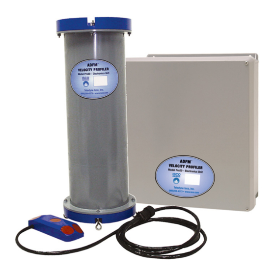
Teledyne ADFM Pro20 Technical Manual (156 pages)
Acoustic Doppler Flow Meter
Brand:
Teledyne
| Category:
Measuring Instruments
| Size: 1 MB
Table of Contents
Table of Contents
7
Introduction to the ADFM Velocity Profiler
15
Overview
15
Getting Started
15
General Operation
16
1-3.1 General Warnings and Cautions
16
ADFM Components Overview
17
Figure 1-1. ADFM Components
17
1-4.1 What Is an ADFM
18
1-4.2 Principles of Operation
18
Figure 1-2. Typical ADFM Installation
18
ADFM Beam Geometry
19
1-4.3 User Data Interfaces
20
Table 1-1: User Data Interface Types
20
Equipment Setup and Installation
21
Introduction
21
Initial Inspection
22
System Interconnection
22
ADFM System Interconnection
22
2-3.1 Connecting the Transducer Cable to the Electronics Unit
23
2-3.2 Power Supply to the ADFM
23
Power Supply Options
23
DC Power Supply Cable
24
Line Voltage Selection
24
Mains (AC) Power Cable
24
2-3.3 Applying Power
25
Built in Tests (Bits)
25
2-4.1 Testing Interval
25
2-4.2 Test Record
25
2-4.3 Power-UP BIT Procedure/Sequence
26
Final Preparations for Use
26
2-5.1 Measure Pipe or Channel Geometry
26
2-5.2 Prepare Installation Hardware
27
Figure 2-2. Pipe Geometry and Parameters
27
2-5.3 Install Software and Configure Station File
28
Figure 2-3. Transducer Orientation
28
2-5.4 Installing and Deploying the ADFM
29
Packaging and Shipping the ADFM
29
2-6.1 Tagging for Service
29
2-6.2 Packaging
29
Software Operation
31
Introduction
31
Computer Requirements
31
Winadfm
32
3-3.1 Related Files
32
Using BBTALK
34
3-4.1 Running BBTALK
34
3-4.2 BBTALK Help
34
BBTALK Menu
34
BBTALK Help Screen
34
3-4.3 Wakeup the ADFM
35
3-4.4 Communication Parameters
35
Figure 3-3. BBTALK Communication Setup Menu
35
3-4.5 BBTALK LOG Files
36
Figure 3-4. BBTALK Log File
36
Maintenance
37
Introduction
37
Desiccant
37
Battery Replacement
38
4-3.1 Replacing the Alkaline Lantern System Batteries
38
4-3.2 Replacing the Lead-Acid System Batteries
39
4-3.3 Recharging the Lead-Acid System Batteries
39
4-3.4 Replacing the Real Time Clock Backup Battery
40
Fuse Replacement
40
Changing Mains Supply Voltage
41
Replacement Parts
42
Figure 4-1. ADFM Electronic Housing (Exterior View) - Replaceable Parts Identification
43
Figure 4-2. ADFM Electronic Housing (Interior View) - Replaceable Parts Identification
44
ADFM Test Procedures
45
Introduction
45
Test Setup
45
Built-In Diagnostic Tests
46
5-3.1 Automatic Built-In Test Test
46
Using BBTALK to Test the ADFM
47
5-4.1 Diagnostic Tests
47
5-4.2 Receive Path Test
48
5-4.3 Transmit Test
49
5-4.4 Sensor Test
50
5-4.5 Modem Test
51
5-4.6 Recorder Test
51
Using Winadfm to Test the ADFM
52
5-5.1 Connect
52
5-5.2 Bench Test
52
Figure 5-1. Winadfm Operate Dialog Window
52
5-5.3 Field Test
53
ADFM Troubleshooting
55
Introduction
55
Equipment Required
56
Table 6-2: Required Test Equipment
56
Power on Fault Isolation
57
Fault Isolation
57
Least Replaceable Assembly Fault Isolation
60
6-5.1 Built-In Test Is Not Executing
60
Communication
60
Table 6-3: List of Test Points
63
6-5.3 BIT Determines a Problem Associated with the Transducer
64
ADFM System Overview
65
Introduction
65
Electronics Unit Circuit Description
65
A-2.1 Power Supply System
65
A-2.2 Receiver
66
A-2.3 Timing Generator
67
A-2.4 Central Processing Unit
67
A-2.5 User Interface
68
Transducer Electronics Circuit Description
69
A-3.1 Multiplexer
69
A-3.2 Transmit Path
69
A-3.3 Receive Path
69
A-3.4 Temperature Interface
70
A-3.5 Transducer Power Supply
70
Figure A-1. Electronics Unit Block Diagram
71
Figure A-2. Transducer Block Diagram
73
Specifications
75
Physical Specifications
75
Figure B-1. ADFM Transducer Dimensions
76
Appendix-B
76
Figure B-2. ADFM Field Housing Dimensions
77
Performance Specifications
78
B-2.1 Measurement Precision
78
Flow Accuracy
78
Velocity
78
Water Level
78
B-2.2 Packaging and Environmental
78
Electronics Unit
78
Transducer
78
Acoustic Frequency
79
Transducer Signal Cable
79
B-2.3 Data Management
79
ADFM Velocity Profiler™ Data Output
79
ADFM Velocity Profiler™ Software
79
Data Interfaces
80
Data Storage (Optional
80
B-2.4 Power and Frequency
80
Power
80
ADFM Commands
81
Introduction
81
C-1.1 ADFM Data Communication and Command Format
82
C-1.2 Command Input Processing
82
C-1.3 Data Output Processing
83
Pipe Heights/Epsilons
84
Command Descriptions
86
Break
87
Help Menus
87
C-2.1 Control System Commands
88
CA - Communication Timeout
88
CB - Serial Port Control (Baud Rate/Parity/Stop Bits
88
CF - Flow Control
89
Table C-3: CMD Description
89
CK - Keep Parameters
90
CL - Leapfrog
90
CN - Site Number
90
CP - Clear BIT Log
90
CR - Retrieve Parameters
90
CS - Start Pinging (Go
91
CT - Turnkey
91
CV - Shut off Voltage
92
CZ - Power down ADFM
92
C-2.2 Environmental Sensor Commands
93
EA Heading Alignment
93
EC - Speed of Sound
93
ED - Depth of Transducer
93
EE - Secondary Depth Max. Probable Error
94
EO - Secondary Depth Zero Offset
94
ER - Secondary Depth Span
94
ES - Salinity
95
ET - Temperature
95
EX - Coord Transform
95
Table C-4: Coordinate Transformation Processing Flags
96
EZ - Sensor Source
97
Table C-5: Sensor Source Switch Settings
97
C-2.3 Modem Commands
98
MC - Modem Command
98
MH - Hangup on Ping Start
98
MI - Modem Answer Init
98
MM - Modem Monitor
99
MN - Dial out Phone Number
100
MO - Check to See if the Modem Is OK
100
MP - Modem Power
100
MT - Modem Terminal
101
MZ - Modem Reset
101
C-2.4 Performance and Test Commands
102
PA - User Interactive Tests
102
PC - Diagnostic Tests
102
PD - Data Stream Select
103
PF - Display Fault Log
103
Table C-6: Data Stream Selections
103
PI Run Individual Built-In Tests
104
PS - Show System Parameters
104
PT - Built-In Tests
105
PT0 - Help
106
Table C-7: Error Code Hex to Binary Conversion
106
PT1 - Board Level Receive Test
107
PT2 - Ancillary System Data
108
PT3 - Receive Path
108
PT4 - Transmit Path
109
PT5 - Electronics Wrap Around
110
PT6 - Receive Bandwidth
111
PT8 - Checksum Lookup Tables
112
C-2.5 Discharge Commands
113
QB - Bed Level
113
QC - Channel Type
113
QD - Algorithm Select
113
QF - Force Depth
114
QH - Pipe Heights/Epsilons
114
QO - Transducer Offset from Pipe Bottom
114
QP - Disc Params
115
QR - QVD Structure Only Rate
115
QU - Channel Geometry Units
115
QW - Pipe Widths/Radii
116
QZ - Zero Discharge Accumulation
116
C-2.6 Recorder Commands
117
RA - Number of Deployments Recorded
117
RB - Blank Check Megabyte
118
RD - Current Deployment Selected
119
RE - Erase Recorder
119
RJ - Number of Ensembles to Jump
119
RS - Recorder Space Used/Free
120
RT - Recorder Bit
121
RY - Start Ymodem
122
C-2.7 Timing Commands
123
TE - Time Per Ensemble
123
TF - Time of First Ping
123
TP - Time Per Ping
124
TS - Set Real-Time Clock
125
C-2.8 Vertical Beam Commands
126
VC - Proofing of Depth
126
VD - Data out
126
VM - Surface Track Mode
126
VN - Vertical Beam Number of Depth Cells
127
VP - Pings Per Ensemble
127
VS - Vertical Beam Depth Cell Size
127
VX - Vertical Beam Transmit Length
127
C-2.9 Water-Profiling Commands
128
WC - Correlation Threshold
128
WD - WT Data out
128
WE - Error Velocity Threshold
128
WF - WT Blank after Transmit
129
WG - Percent Good Minimum
129
WM - WT Profiling Mode
129
WN - WT Number of Depth Cells
130
WO - Single Beam Mode Select
130
WP - WT Pings Per Ensemble
130
WS - WT Depth Cell Size
130
WV - WT Mode 1 Ambiguity Velocity
131
ADFM Hot Tap Insertion
133
ADFM Analog Output Module
139
Appendix-E
140
February
153
Advertisement
Teledyne ADFM Pro20 Installation And Operation Manual (116 pages)
Acoustic Doppler Flow Meters
Brand:
Teledyne
| Category:
Measuring Instruments
| Size: 7 MB
Table of Contents
Table of Contents
7
Section 1 Introduction
11
Overview
11
Initial Inspection
12
Technical Specifications
12
Technical Specifications: ADFM Controller
12
Technical Specifications: Hot Tap Insertion Velocity Sensor
14
Operating Principles
15
Communication and Data Interfacing
18
Optional Interfacing Tools
18
Technical Specifications: Pro20 Open Channel Velocity Sensor
14
Section 2 Setup and Installation
21
Software
21
Flowlink Software
21
Flowlink Flow Rate Tab: Rectangular Channel
25
Flowlink Flow Rate Tab: Multi-Point Channels
26
Winadfm Software
28
Setup
28
Site Tab Window
29
Irregular Channel Configure Window
31
Communication Tab
32
Profiling Tab
33
Connecting to the ADFM
35
Connect Screen
35
Preparing for Installation
38
Installation Checklist
38
Basic Configuration
39
ADFM System Configuration with Box Controller
39
ADFM System Configuration with Canister Controller
40
Power Selection
41
Site Requirements
42
Installing the Electronics Controller
42
ADFM Controller: Wall Mounting
42
ADFM Controller: Environmental Console Enclosure
43
ADFM Controller: Cylindrical Canister Suspended in Manhole
44
Connector Port Changes in the Canister Controller
44
Sensor Installation
45
General Cabling and Connection
45
Pro20 Sensor Installation
45
Pro20: Channel Geometry
45
Common Pipe and Channel Shapes
46
Sensor Positioning
47
Pro20: Cabling
48
Circular Channels
49
Scissors Ring
50
Flatten Six Center Tabs on Base Section
51
Ring Assembled, Ready for Installation
52
Large Flows and Moving Debris
53
Rectangular Channels
53
Attaching the Sensor to a Mounting Plate
54
Applications with Permanent Silt
55
Fairing and Spacers for Added Lift
56
Attaching the Mounting Plate
57
Pro20 Sensor Mounting Hardware
58
Hot Tap Sensor Installation
59
Forced Depth and Scaling Constant (Hot Tap Only)
60
Insertion: Early Version HTI
61
Early HTI: Component Measurements and Sensor Positioning
62
Early HTI Hardware
63
Secondary Collar Installation
64
Early Version Hot Tap with Secondary Collar Installed
65
Insertion: Current HTI
66
Current HTI: Component Measurements and Sensor Positioning
67
Current HTI Hardware
68
Align the Edges of the Box Parallel to Flow
69
Adjust Chain to Proper Length
70
Applying Power
71
Box Controller Batteries
71
Box: Battery Compartment
72
Box Controller on and Reset Switches
73
Canister Controller Batteries
74
Resetting the ADFM Canister
75
Built in Tests (Bits) (Box Controller Only)
76
Testing Interval
76
Test Record
76
Power-Up BIT Procedure/Sequence
76
BIT Hexadecimal Code Definitions
77
Data Retrieval
78
Flowlink
78
Flowlink: Data Download
79
Viewing the Data
80
Flowlink: Drag & Drop Data Parameters on Graph (Velocity and Flow Shown)
81
Winadfm
82
Collect/Erase Data
83
Viewing the Data
84
Viewing Data in Expert View
85
Section 3 Maintenance and Troubleshooting
87
How to Obtain Service
87
Cleaning
87
Packaging
87
Desiccant
88
Box Controller Desiccant
88
Internal Desiccant Canister
89
Canister Controller Desiccant
90
Real Time Clock Backup Battery
91
Troubleshooting the ADFM
92
Troubleshooting Tables
92
Troubleshooting on Power-Up
92
Troubleshooting Steps
93
Troubleshooting During Operation
93
BIT Not Executing (Box Controller Only)
94
BIT Determines a Problem Associated with the Sensor
95
Sensor Malfunction with Canister Controller
96
Canister Controller: Opening the Electronics Lid
97
Appendix A Parts and Accessories
99
General Spare Parts and Accessories
99
Pro20 Debris Fairing Kits
100
Secondary Depth Sensors
100
A.2 Standard Pro20 Mounting Rings
100
Appendix B Material Safety Data Sheets
101
Advertisement
Related Products
Teledyne PEM-9004
Teledyne PS200 Series
Teledyne PS200-LMP
Teledyne PMAT 2000
Teledyne TEXIO PTE6-200
Teledyne ADFM Analog Output Module
Teledyne ADFM Hot Tap
Teledyne ProEM Series
Teledyne ProEM:512B
Teledyne ProEM:512BK
Teledyne Categories
Measuring Instruments
Analytical Instruments
Test Equipment
Digital Camera
Laboratory Equipment
More Teledyne Manuals
Login
Sign In
OR
Sign in with Facebook
Sign in with Google
Upload manual
Upload from disk
Upload from URL