Sign In
Upload
Manuals
Brands
Sun Microsystems Manuals
Server
Netra T2000
Sun Microsystems Netra T2000 Server Manuals
Manuals and User Guides for Sun Microsystems Netra T2000 Server. We have
4
Sun Microsystems Netra T2000 Server manuals available for free PDF download: Service Manual, Administration Manual, Installation Manual
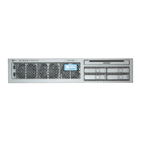
Sun Microsystems Netra T2000 Service Manual (166 pages)
Brand:
Sun Microsystems
| Category:
Server
| Size: 3 MB
Table of Contents
Service Manual
1
Table of Contents
5
Preface
17
How this Book Is Organized
17
Additional Service Related Information
18
Typographic Conventions
19
Sun Welcomes Your Comments
21
1 Safety Information
23
Safety Symbols
23
Electrostatic Discharge Safety
24
Using an Antistatic Wrist Strap
24
Using an Antistatic Mat
24
2 Server Overview
25
Server Features
26
Chip Multitheaded Multicore Processor and Memory Technology
26
FIGURE 2-1 Server
26
FIGURE 2-2 Motherboard and Ultrasparc T1 Multicore Processor
27
Performance Enhancements
28
Remote Manageability with ALOM CMT
29
System Reliability, Availability, and Serviceability
30
Hot-Pluggable and Hot-Swappable Components
31
Power Supply Redundancy
31
Fan Redundancy
31
Environmental Monitoring
31
Error Correction and Parity Checking
32
Predictive Self-Healing
32
Chassis Identification
33
Obtaining the Chassis Serial Number
34
3 Server Diagnostics
35
Overview of Server Diagnostics
35
Table
36
FIGURE 3-1 Diagnostic Flow Chart
37
TABLE 3-1 Diagnostic Flowchart Actions
38
Memory Configuration and Fault Handling
40
Memory Configuration
40
Memory Fault Handling
41
Troubleshooting Memory Faults
42
Using Leds to Identify the State of Devices
42
Front and Rear Panel Leds
42
FIGURE 3-2 Front Panel Leds
43
FIGURE 3-3 Rear Panel Leds
43
TABLE 3-2 Front and Rear Panel Leds
44
Hard Drive Leds
45
Power Supply Leds
46
FIGURE 3-5 Power Supply Leds
46
TABLE 3-4 Power Supply Leds
46
Fan Leds
47
Blower Unit LED
47
FIGURE 3-6 Location of Fan Leds
47
TABLE 3-5 Fan Leds
47
Ethernet Port Leds
48
FIGURE 3-7 Location of the Blower Unit LED
48
TABLE 3-6 Blower Unit LED
48
FIGURE 3-8 Ethernet Port Leds
49
TABLE 3-7 Ethernet Port Leds
49
Using ALOM CMT for Diagnosis and Repair Verification
50
FIGURE 3-9 ALOM CMT Fault Management
50
Running ALOM CMT Service-Related Commands
52
Connecting to ALOM CMT
52
Switching between the System Console and ALOM CMT
52
Service-Related ALOM CMT Commands
53
TABLE 3-8 Service-Related ALOM CMT Commands
53
Running the Showfaults Command
55
Running the Showenvironment Command
56
Running the Showfru Command
59
Running POST
60
Controlling How POST Runs
60
TABLE 3-9 ALOM CMT Parameters Used for POST Configuration
61
FIGURE 3-10 Flowchart of ALOM CMT Variables for POST Configuration
63
Changing POST Parameters
64
Reasons to Run POST
65
Verifying Hardware Functionality
65
Diagnosing the System Hardware
66
Running POST in Maximum Mode
66
Correctable Errors Detected by POST
70
Correctable Errors for Single Dimms
71
Determining When to Replace Detected Devices
72
Clearing POST Detected Faults
73
Using the Solaris Predictive Self-Healing Feature
74
Identifying PSH Detected Faults
75
Using the Fmdump Command to Identify Faults
76
Clearing PSH Detected Faults
78
Collecting Information from Solaris os Files and Commands
79
Checking the Message Buffer
79
Viewing System Message Log Files
79
Managing Components with Automatic System Recovery Commands
80
TABLE 3-11 ASR Commands
80
Displaying System Components
81
Disabling Components
82
Enabling Disabled Components
82
Exercising the System with Sunvts
83
Checking Whether Sunvts Software Is Installed
83
Exercising the System Using Sunvts Software
84
Exercising the System with Sunvts Software
85
FIGURE 3-11 Sunvts GUI
86
FIGURE 3-12 Sunvts Test Selection Panel
87
TABLE 3-12 Useful Sunvts Tests to Run on this Server
87
4 Replacing Hot-Swappable and Hot-Pluggable Frus
89
Devices that Are Hot-Swappable and Hot-Pluggable
90
Hot-Swapping a Fan
90
Removing a Fan
90
FIGURE 4-1 Fan Identification and Removal
91
Replacing a Fan
92
Hot-Swapping a Power Supply
92
Removing a Power Supply
92
FIGURE 4-2 Locating Power Supplies and Release Latch
93
Replacing a Power Supply
94
FIGURE 4-3 Rotating the Cable Management Arm
94
Hot-Swapping the Rear Blower
95
Removing the Rear Blower
95
Replacing the Rear Blower
95
FIGURE 4-4 Removing the Rear Blower
95
FIGURE 4-5 Replacing the Blower Unit
96
Hot-Plugging a Hard Drive
97
Removing a Hard Drive
97
Replacing a Hard Drive
98
FIGURE 4-6 Locating the Hard Drive Release Button and Latch
98
5 Replacing Cold-Swappable Frus
101
Common Procedures for Parts Replacement
101
Required Tools
102
Shutting the System down
102
Extending the Server to the Maintenance Position
103
Removing the Server from a Rack
104
FIGURE 5-1 Slide Release Latches
104
FIGURE 5-2 Locating the Metal Lever
105
Disconnecting Power from the Server
106
Performing Electrostatic Discharge Prevention Measures
106
Removing the Top Cover
106
Removing the Front Bezel and Top Front Cover
107
FIGURE 5-3 Top Cover and Release Button
107
Removing and Replacing Frus
108
FIGURE 5-4 Removing the Front Bezel from the Server Chassis
108
Removing PCI-Express and PCI-X Cards
109
FIGURE 5-6 Location of PCI-Express and PCI-X Card Slots
110
FIGURE 5-7 PCI Card and Hold-Down Bracket
111
Replacing PCI Cards
111
Removing Dimms
112
FIGURE 5-8 DIMM Locations
113
TABLE 5-1 DIMM Names and Socket Numbers
113
Replacing Dimms
114
Removing the System Controller Card
117
FIGURE 5-10 Locating the System Configuration PROM
118
FIGURE 5-9 Ejecting and Removing the System Controller Card
118
Replacing the System Controller Card
118
Removing the Motherboard Assembly
119
FIGURE 5-11 Motherboard Assembly
120
FIGURE 5-12 Cable Cutout
121
FIGURE 5-13 Location of the Screws in the Motherboard Assembly
122
FIGURE 5-14 Removing the Motherboard Assembly from the Server Chassis
123
Replacing the Motherboard Assembly
123
FIGURE 5-15 Installing the Motherboard Assembly
125
FIGURE 5-16 Securing the Motherboard Assembly to the Chassis
126
Removing the Power Distribution Board
127
FIGURE 5-17 Location of Power Supply Latch
128
FIGURE 5-18 Location of Bus Bar Screws on the Power Distribution Board and the Motherboard Assembly
129
FIGURE 5-19 Removing the Power Distribution Board
130
Replacing the Power Distribution Board
130
FIGURE 5-20 Installing the Power Distribution Board
131
Removing the LED Board
132
FIGURE 5-21 Removing the LED Board from the Chassis
133
Replacing the LED Board
133
FIGURE 5-22 Removing the Fan Power Board
134
Removing the Fan Power Board
134
Replacing the Fan Power Board
134
FIGURE 5-23 Removing the Fan Guard
135
Removing the Front I/O Board
135
FIGURE 5-24 Removing the Front I/O Board
136
Replacing the Front I/O Board
136
Removing the DVD Drive
137
Removing the SAS Disk Backplane
137
Replacing the DVD Drive
137
FIGURE 5-25 Removing the SAS Disk Backplane
138
Replacing the SAS Disk Backplane
138
FIGURE 5-26 Replacing the SAS Disk Backplane
139
FIGURE 5-27 Removing the Battery from the System Controller
140
FIGURE 5-28 Replacing the Battery in the System Controller
140
Removing the Battery on the System Controller
140
Replacing the Battery on the System Controller
140
Common Procedures for Finishing up
141
Replacing the Top Front Cover and Front Bezel
141
FIGURE 5-29 Replacing the Top
141
Replacing the Top Cover
142
Reinstalling the Server Chassis in the Rack
142
FIGURE 5-30 Returning the Server to the Rack
143
FIGURE 5-31 Release Levers
144
Applying Power to the Server
145
FIGURE 5-32 Installing the CMA
145
6 Adding New Components and Devices
147
Adding Hot-Pluggable and Hot-Swappable Devices
147
Adding a Hard Drive to the Server
147
Adding a USB Device
149
Adding Components Inside the Chassis
150
Memory Guidelines
150
FIGURE 6-2 Adding a USB Device
150
FIGURE 6-3 DIMM Layout
151
Adding Dimms
152
TABLE 6-1 DIMM Names and Socket Numbers
152
FIGURE 6-4 Location of PCI-Express and PCI-X Card Slots
153
FIGURE A-1 Field-Replaceable Units (1
156
FIGURE A-2 Field-Replaceable Units (2
157
TABLE A-1 Server FRU List
158
Advertisement
Sun Microsystems Netra T2000 Administration Manual (122 pages)
Server
Brand:
Sun Microsystems
| Category:
Server
| Size: 0 MB
Table of Contents
Table of Contents
3
Table of Contents
11
Preface
13
How this Document Is Organized
13
Typographic Conventions
14
Related Documentation
15
Sun Welcomes Your Comments
16
1 System Console
17
Communicating with the System Console
17
Serial Management Port
17
Establishing Communication with the Serial Management Port
18
TABLE 1-1 Pin Crossovers for Connecting to a Typical Terminal Server
19
To Access the System Console through the Tip Connection
19
TABLE 1-2 Entries for Hardwire in the /Etc/Remote File
20
Network Management Port
21
Switching between the Consoles
22
ALOM Sc> Prompt
23
To Obtain the ALOM Prompt from the Openboot PROM
24
To Obtain the ALOM Prompt from the Solaris Console
24
Openboot PROM Ok Prompt
25
To Connect to the Solaris Console from the ALOM Prompt
25
To Obtain the Openboot Prompt from the ALOM Prompt
26
To Obtain the Openboot Prompt When the Solaris os Is Running
26
To Terminate a Session When Connected to the System Controller through the Serial Port
26
To Terminate a Session When Connected to the System Controller through a Network Connection
27
2 Advanced Lights out Manager
29
ALOM Overview
29
ALOM Features
29
TABLE 2-1 What ALOM Monitors
30
Using ALOM
30
What ALOM Monitors
30
To Set the Initial Password
31
ALOM Shell Commands
32
Configuration Commands
32
TABLE 2-2 ALOM Configuration Commands
32
FRU Commands
33
TABLE 2-3 ALOM FRU Commands
33
Table
33
Command
33
Summary
33
Example
33
Log Commands
34
Status and Control Commands
34
TABLE 2-4 ALOM Log Commands
34
TABLE 2-5 ALOM Status and Control Commands
34
Skip the Confirmation Question
35
Other Alom Commands
36
Basic ALOM Tasks
36
To Reset ALOM
36
TABLE 2-6 Other ALOM Commands
36
To Switch between the System Console and ALOM
37
To Control the Locator LED
37
To Reset the Host Server
37
To View Environmental Information about the Server
37
To Reconfigure ALOM to Use the Ethernet (NET MGT) Port
38
To Add ALOM User Accounts
39
To Remove an ALOM User Account
39
To Log in to ALOM
40
To Change an ALOM Password
40
To Set up Email Alerts
40
To Back up Your ALOM Configuration
41
To Display Your ALOM Version
41
3 Openboot PROM
43
Openboot PROM Overview
43
Before You Obtain the Ok Prompt
44
Obtaining the Ok Prompt
44
ALOM Break or Console Command
45
Graceful Shutdown
45
Stop-A Keys or Break Key
45
Manual System Reset
46
TABLE 3-1 Methods of Obtaining the Ok Prompt
46
To Obtain the Ok Prompt
46
Openboot PROM Configuration Variables
47
TABLE 3-2 Openboot Configuration Variables Stored on the System Configuration Card
47
To Change an Openboot PROM Configuration Variable
47
Openboot Emergency Procedures
49
Stop-A Functionality
49
Stop-N Functionality
50
To Restore Openboot Configuration Defaults
50
Stop-D Functionality
51
Stop-F Functionality
51
Basic Administrative Tasks
53
Status Indicators
53
Interpreting Status Leds
54
TABLE 4-1 LED Behavior and Meaning
54
TABLE 4-2 LED Behaviors with Assigned Meanings
54
Bezel Server Status Indicators
55
TABLE 4-3 Bezel Server Status Indicators
56
Alarm Status Indicators
57
TABLE 4-4 Locator LED Commands
57
TABLE 4-5 Alarm Indicators and Dry Contact Alarm States
58
Selecting a Boot Device
59
To Select a Boot Device
60
TABLE 4-6 Device Identifiers and Devices
61
To Unconfigure a Device Manually
61
Unconfiguring and Reconfiguring Devices
61
To Reconfigure a Device Manually
62
Displaying System Fault Information
62
To Display System Fault Information
62
Multipathing Software
63
Automatic System Recovery
64
Autoboot Options
65
Error Handling Summary
65
To Enable Automatic Degraded Boot
65
To Enable Asr
66
Storing FRU Information
64
To Store Information in Available Fru Proms
64
Updating the Firmware
67
To Disable Asr
67
To Update the Server Firmware
68
5 Securing the Server
71
Security Guidelines
71
Defining the Console Password
72
Rebooting the System Controller to Implement Settings
72
Using the Snmp Protocol Default Configuration
72
TABLE 5-1 SSH Server Attributes
73
Selecting a Remote Connection Type
73
Enabling Ssh
73
To Enable Ssh
74
Features Not Supported by SSH
75
Changing SSH Host Keys
76
Additional Security Considerations
76
Special Key Sequences for Rtos Shell Access
76
Domain Minimization
77
Solaris Operating System Security
77
6 Managing Disk Volumes
79
Raid Requirements
79
Disk Volumes
80
Raid Technology
80
Integrated Mirror Volumes (Raid)
81
Integrated Stripe Volumes (Raid)
81
Hardware RAID Operations
82
TABLE 6-1 Disk Slot Numbers, Logical Device Names, and Physical Device Names
83
Slot Numbers and Device Names for Non-RAID Disks
83
To Create a Mirrored Volume
83
To Create a Striped Volume
87
To Configure and Label a Raid Volume
89
To Delete a Raid Volume
92
To Perform a Mirrored Disk Hot-Swap Operation
94
Watchdog Timer Application Mode
101
Understanding the Watchdog Timer Application Mode
101
Appendix
102
Watchdog Timer Limitations
102
Understanding the User API
104
Enabling or Disabling the Watchdog
105
Setting the Timeout Period
105
Using the Watchdog Timer
105
Finding and Defining Data Structures
106
Getting the State of the Watchdog Timer
106
Rearming the Watchdog
106
Example Watchdog Program
107
Programming Alarm3
108
TABLE A-1 Alarm3 Behavior
108
TABLE A-2 Watchdog Timer Error Messages
110
Watchdog Timer Error Messages
110
Using the Ntwdt Driver
104
Sun Microsystems Netra T2000 Installation Manual (116 pages)
Netra T2000 Server Installation Guide
Brand:
Sun Microsystems
| Category:
Server
| Size: 8 MB
Table of Contents
Table of Contents
3
How this Document Is Organized
13
Typographic Conventions
14
Related Documentation
15
Sun Welcomes Your Comments
16
Server Views
17
FIGURE 1-1 Netra T2000 Server Front Panel
17
FIGURE 1-2 Netra T2000 Server Rear Panel
18
FIGURE 1-3 Netra T2000 Server
18
Server Features
19
TABLE 4 Server Features
19
Chip-Multitheaded Multicore Processor and Memory Technology
20
FIGURE 1-5 Ultrasparc T1 Multicore Processor Block Diagram
21
Performance Enhancements
21
Preinstalled Solaris Operating System
21
Preloaded Java Enterprise System Software
22
Hardware-Assisted Cryptography
23
Remote Server Management with ALOM
23
System Reliability, Availability, and Serviceability
24
Hot-Swappable Components
24
Power Supply Redundancy
25
Fan Redundancy
25
Environmental Monitoring
25
Error Correction and Parity Checking
26
Fault Management and Predictive Self-Healing
26
Rackmountable Enclosure
27
Tools Needed
29
Shipping Kit Inventory List
29
Installation Overview
30
Installing the Air Filter
32
FIGURE 2-1 Finger Holds on Bezel
32
Installing Optional Components
33
FIGURE 2-2 Installing the Air Filter in the Bezel
33
Slide Rail Assembly Notes
34
FIGURE 2-3 Sections of the Slide Rail Assembly
34
FIGURE 2-4 Locating the Locks on the Slide Rail Assembly
35
Safety Precautions
36
4-Post Rackmounting Options
38
Hardmounting the Server in a 19-Inch 4-Post Rack
38
To Install a Server with a Hardmount 19-Inch 4-Post Rack
38
TABLE 3-1 Optional Rackmount Kits
38
FIGURE 3-1 Contents of the Hardmount 19-Inch 4-Post Kit
39
TABLE 3-2 19-Inch 4-Post Rackmount Screw Kit Contents
39
FIGURE 3-2 Securing the Hardmount Brackets to the Server
40
FIGURE 3-3 Attaching the Rear Mount Support Brackets
41
FIGURE 3-4 Securing the Front of the Server to the Rack
41
Mounting the Server in a Sliding Rail Mount 19-Inch 4-Post Rack
42
FIGURE 3-5 Securing the Rear of the Server to the Rack
42
TABLE 3-3 Sliding Rail 19-Inch 4-Post Rackmount Screw Kit Contents
43
FIGURE 3-6 Contents of the Sliding Rail 19-Inch 4-Post Kit
43
FIGURE 3-7 Securing the Hardmount Bracket to the Server
44
FIGURE 3-8 Dismantling the Slide
45
FIGURE 3-9 Fixing the Glides to the Server Chassis
45
FIGURE 3-10 Securing the Brackets to the Rack
46
FIGURE 3-11 Securing the Slide to the Brackets
47
FIGURE 3-13 Securing the Front of the Server to the Rack
48
FIGURE 3-12 Sliding the Server into the Rack
48
Hardmounting the Server in a 600-MM 4-Post Rack
49
To Install a Server with a Hardmount in a 600-MM 4-Post Rack
49
FIGURE 3-14 Contents of the Hardmount 600-MM 4-Post Kit
50
TABLE 3-4 Hardmount 600 MM 4-Post Rackmount Screw Kit Contents
50
FIGURE 3-15 Adjustable Rail Screws
51
FIGURE 3-16 Securing the Front of the Adjustable Rails to the Rack
52
FIGURE 3-17 Securing the Rear of the Adjustable Rails to the Rack
53
FIGURE 3-18 Installing the Rear Flange Onto the Adjustable Rail
54
FIGURE 3-19 Securing the Side Rails to the Server
55
FIGURE 3-20 Sliding the Server Onto the Adjustable Rails
55
FIGURE 3-21 Securing the Rear of the Server to the Rear Flanges
56
Installing a Server with a Hardmount in a 19-Inch 4-Post Rack for Use with the Cable Management Assembly
57
FIGURE 3-22 Securing the Front of the Server to the Front of the Rack
57
FIGURE 3-23 Unlocking the Slide Rail Assembly
58
To Install the Slide Rail Assemblies
58
FIGURE 3-24 Location of the Mounting Bracket Release Button
59
FIGURE 3-25 Unlocking the Slide Rail Middle Section
59
FIGURE 3-26 Attaching a Mounting Bracket to the Chassis
60
FIGURE 3-27 Mounting a Slide Rail
61
FIGURE 3-28 Adjusting the Distance between the Slide Rails
62
FIGURE 3-29 Mounting the Chassis on the Slide Rails
63
To Install the Cable Management Assembly
63
FIGURE 3-30 Inserting the CMA Rail Extension into the Rear of the Left Slide Rail
64
FIGURE 3-31 Mounting the Inner CMA Connector
65
FIGURE 3-32 Attaching the Outer CMA Connector
65
FIGURE 3-33 Mounting the Left Side of the Rail
66
To Verify the Operation of the Slide Rails and the CMA
66
FIGURE 3-34 Unlocking the Slide Rail Assembly
67
FIGURE 3-35 Unlocking the Slide Rail Lever Stops
68
FIGURE 3-36 Slide Rail Release Button
68
2-Post Rackmounting Options
72
Hardmounting the Server in a 23-Inch 2-Post Rack
72
To Install a Server with a Hardmount in a 23-Inch 2-Post Rack
72
TABLE 4-1 Optional Rackmount Kits
72
FIGURE 4-1 Contents of the Hardmount 23-Inch 2-Post Kit
73
TABLE 4-2 Hardmount 23-Inch 2-Post Rackmount Screw Kit Contents
73
FIGURE 4-2 Securing the Side Brackets to the Side of the Server
74
FIGURE 4-3 Installing the Rail Guides in the Rack
74
FIGURE 4-4 Installing and Securing the Server in the 2-Post Rack
75
FIGURE 4-5 Installing a Screw on the Middle Rack Position on the Rear Plate
76
Hardmounting the Server in a 19-Inch 2-Post Rack
77
To Install a Server with a Hardmount in a 19-Inch 2-Post Rack
77
FIGURE 4-7 Securing the Rear Plate to the Back of the Post
77
FIGURE 4-8 Contents of the Hardmount 19-Inch 2-Post Kit
78
TABLE 4-3 Hardmount 19-Inch 2-Post Rackmount Screw Kit Contents
78
FIGURE 4-9 Securing the Side Brackets to the Side of the Server
79
FIGURE 4-10 Installing and Securing the Server in the 2-Post Rack
79
FIGURE 4-11 Installing Screws on the Optimum Rack Position on the Rear Plate
80
FIGURE 4-12 Installing the Rear Plate to the Side Bracket
81
FIGURE 4-13 Securing the Rear Plate to the Rack
82
Data Ports and Cabling Notes
83
Port Locations
83
Cabling Notes
84
FIGURE 5-1 Rear Panel Features
84
Connecting Cables
85
To Connect the Ethernet Network Cables
85
To Connect the SC Serial Management Port
86
FIGURE 5-2 Ethernet Network Connections
86
To Connect the SC Network Management Port
87
FIGURE 5-3 System Controller Serial Connection
87
Input Power Cables
88
TTYA Serial Port
88
FIGURE 5-4 System Controller Network Connection
88
USB Ports
89
FIGURE 5-5 Serial Port
89
Alarm Port
90
FIGURE 5-6 USB Ports
90
FIGURE 5-7 Alarm Port
90
Managing Cables with the CMA
91
To Open and Close a Cable Clip
91
FIGURE 5-8 Opening a Cable Clip
91
FIGURE 5-9 Removing a Cable Clip
92
FIGURE 5-10 Mounting or Moving a Cable Clip
92
Powering on the Server for the First Time
93
FIGURE 6-1 Rear Panel Power Connectors
94
To Power on the Server for the First Time
94
Enabling the System Controller Network Management Port
96
Logging into the System Controller
96
To Log into the System Controller Using the Serial Management Port
96
To Configure the System Controller Network Management Port
97
TABLE 6-1 Sample Configuration Parameter Setting
99
To Reset the System Controller
100
To Log into the System Controller Using the Network Management Port
101
Using the System Controller for Common Operations
102
To Power on the Server
102
To Connect to the System Console
103
To Perform a Normal Server Initialization
103
TABLE 6-2 Map of Devices, Openboot Path Names, and Locations
104
Booting the Solaris Operating System
105
To Boot the Solaris Operating System
105
To Reset the Server
106
To Power Cycle the Server
106
TABLE A-1 Server Software Configuration Worksheet
109
Advertisement
Sun Microsystems Netra T2000 Service Manual (138 pages)
Brand:
Sun Microsystems
| Category:
Server
| Size: 23 MB
Table of Contents
Service Manual
1
Table of Contents
3
Preface
9
How this Book Is Organized
10
Typographic Conventions
12
Contacting Sun Technical Support
13
Sun Welcomes Your Comments
13
1 Sun Fire T2000 Server Overview
15
Sun Fire T2000 Server Features
16
Chip-Multitheaded (CMT) Multicore Processor and Memory Technology
16
Performance Enhancements
18
Remote Manageability with ALOM
19
System Reliability, Availability, and Serviceability
19
Fan Redundancy
20
Hot-Pluggable and Hot-Swappable Components
20
Power Supply Redundancy
20
Environmental Monitoring
21
Error Correction and Parity Checking
21
Predictive Self Healing
21
Chassis Identification
23
Additional Service Related Information
24
2 Sun Fire T2000 Server Diagnostics
25
Overview of Sun Fire T2000 Server Diagnostics
26
Using Leds to Identify the State of Devices
30
Front and Rear Panel Leds
30
Hard Drive Leds
33
Power Supply Leds
34
Fan Leds
35
Blower Unit LED
35
Using ALOM for Diagnosis and Repair Verification
36
Running ALOM Service-Related Commands
38
Connecting to ALOM
38
Switching between the System Console and ALOM
38
Service-Related ALOM Commands
39
To Run the Showfaults Command
40
To Run the Showenvironment Command
41
To Run the Showfru Command
43
Running POST
45
Controlling How POST Runs
45
To Change POST Parameters
48
Reasons to Run POST
49
Diagnosing the System Hardware
49
Routine Sanity Check of the Hardware
49
To Run POST
49
Using the Solaris Predictive Self-Healing Feature
54
To Use the Fmdump Command to Identify Faults
55
Collecting Information from Solaris os Files and Commands
57
To Check the Message Buffer
57
To View System Message Log Files
57
Managing Components with Automatic System Recovery (ASR) Commands
58
To Run the Showcomponent Command
60
To Run the Disablecomponent Command
61
To Run the Enablecomponent Command
61
Exercising the System with Sunvts
62
Checking Whether Sunvts Software Is Installed
62
To Check Whether Sunvts Software Is Installed
62
Exercising the System Using Sunvts Software
64
To Exercise the System Using Sunvts Software
64
For Further Information, Refer to the Manuals that Accompany the Sunvts Software
67
3 Replacing Hot-Swappable and Hot-Pluggable Frus
69
Devices that Are Hot-Swappable and Hot-Pluggable
70
Hot-Swapping a Fan
70
To Remove a Fan
71
Hot-Swapping a Power Supply
72
To Remove a Power Supply
72
To Replace a Power Supply
74
Hot-Swapping the Rear Blower
75
To Remove the Rear Blower
75
To Replace the Rear Blower
75
Hot-Plugging a Hard Drive
77
To Remove a Hard Drive
77
To Replace a Hard Drive
78
4 Replacing Cold Swappable Frus
79
Safety Information
80
Safety Symbols
80
Electrostatic Discharge Safety
81
Use an Antistatic Mat
81
Use an Antistatic Wrist Strap
81
Common Procedures for Parts Replacement
81
Required Tools
82
To Shut the System down
82
To Extend the Server to the Maintenance Position
83
To Remove the Server from the Rack
84
To Disconnect Power from the Server
86
To Perform Electrostatic Discharge (ESD) Prevention Measures
86
To Remove the Top Cover
86
To Remove the Front Bezel and Top
87
Removing and Replacing Frus
88
To Remove PCI-E and PCI-X Cards
89
To Replace PCI Cards
91
To Remove Dimms
91
To Replace Dimms
93
To Remove the System Controller
96
To Replace the System Controller Board
97
To Remove the Motherboard Assembly
98
To Replace the Motherboard Assembly
102
To Remove the Power Distribution Board
104
To Replace the Power Distribution Board
106
To Remove the LED Board
107
To Replace the LED Board
108
To Remove the Fan Power Board
109
To Replace the Fan Power Board
110
To Remove the Front I/O Board
110
To Replace the Front I/O Board
111
To Remove the DVD Drive
112
To Replace the DVD Drive
113
To Remove the SAS Disk Backplane
113
To Replace the SAS Disk Backplane
114
To Remove the Battery on the System Controller
115
To Replace the Battery on the System Controller
115
Common Procedures for Finishing up
117
To Replace the Top Front Cover and Front Bezel
117
To Reinstall Server Chassis in the Rack
118
To Replace the Top Cover
118
To Return the Server to the Normal Rack Position
119
To Apply Power to the Server
121
5 Adding New Components and Devices
123
Adding Hot-Pluggable and Hot-Swappable Devices
124
To Add a Hard Drive to the Server
124
To Add a USB Device
125
Adding Components Inside the Chassis
127
To Add Dimms
127
To Add a PCI-E or PCI-X Card
130
Field-Replaceable Units
133
Advertisement
Related Products
Sun Microsystems Sun Fire T200
Sun Microsystems Sun Blade T6300
Sun Microsystems Sun Fire T1000
Sun Microsystems SPARC T5120
Sun Microsystems SPARC T5220
Sun Microsystems Netra T4 AC100
Sun Microsystems Netra T4 DC100
Sun Microsystems Netra T1 AC200
Sun Microsystems Netra T1 DC200
Sun Microsystems SPARC Enterprise T5240
Sun Microsystems Categories
Server
Storage
Desktop
Computer Hardware
Adapter
More Sun Microsystems Manuals
Login
Sign In
OR
Sign in with Facebook
Sign in with Google
Upload manual
Upload from disk
Upload from URL