Sign In
Upload
Manuals
Brands
Siemens Manuals
Accessories
SIWAREX WP251
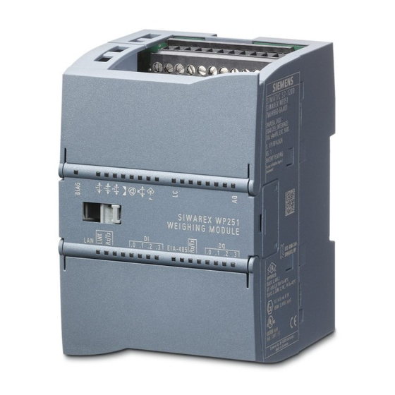
Siemens SIWAREX WP251 Manuals
Manuals and User Guides for Siemens SIWAREX WP251. We have
2
Siemens SIWAREX WP251 manuals available for free PDF download: Operating Instructions Manual, Manual
Siemens SIWAREX WP251 Manual (220 pages)
Electronic Weighing System
Brand:
Siemens
| Category:
Accessories
| Size: 3 MB
Table of Contents
Table of Contents
3
Table of Contents
13
Introduction
15
Purpose of the Manual
15
Basic Knowledge Required
15
Manual - Range of Validity
15
Technical Support
15
Safety Notes
17
General Safety Instructions
17
Security Messages
17
Description
19
Product Overview
19
Area of Application
19
System Integration in SIMATIC
19
Scope of Delivery
20
Image 3-1 System Overview
20
Application Planning
21
Functions
21
Parameter Assignment Options
21
Parameter Assignment with the PC
21
Parameter Assignment with a SIMATIC Panel
22
Image 4-1 SIWATOOL Overview
22
Parameter Assignment by Means of the Modbus Interface
23
Image 4-2 SIWAREX WP251 in Stand-Alone Operation
23
Mounting
25
Installation Guideline
25
EMC-Compliant Installation
25
Introduction
25
Possible Effects of Interference
25
Coupling Mechanisms
26
Five Basic Rules for Securing EMC
26
Mounting on the SIMATIC S7-1200
27
Connection
29
Overview
29
Image 6-1 SIWAREX WP251 Connection Areas
29
Connection
30
Connecting the Load Cells
30
Table 6- 1 Connection of the 24 V Supply
30
Shield Connection
31
Table 6- 2 Load Cell Connections on the Module
31
Image 6-2 Shielding in the Screw Gland
31
Image 6-3 Installation of the Shield Connection Element (Example)
32
Image 6-4 Connection of Strain Gauge Load Cell with 4-Wire System
33
Connection of Digital Outputs (4 X DQ)
34
Image 6-5 Connection of Strain Gauge Load Cell with 6-Wire System
34
Image
34
Connection of Digital Inputs (4 X DI)
35
Table 6- 3 Connection of the Digital Outputs
35
Connection of the Analog Output (1 X AQ)
36
Connection of RS485 Serial Interface
36
Connection of Siebert Display Via RS485
37
Connection of Siebert Display S102
37
Connection of the Ethernet Interface
38
Activation of Write Protection
38
Attachment of Calibration Protection Plate
39
Image 6-7 Attachment of the Calibration Protection Plates
39
Commissioning
41
Introduction
41
Factory Setting of the Mode Selector
41
Image 7-1 Mode Switch
41
Automatic Quick Calibration with SIWATOOL
42
Overview
42
Activate Service Mode
43
Load Standard Parameters
43
Image 7-2 Quick Calibration with Marked Parameters
43
Image
43
Input of Required Parameters
44
Sending/Receiving a Data Record / in SIWATOOL V7
44
Image
44
Complete Automatic Calibration
45
Receive All Data
45
Checking the Scale after Calibration
45
Quick Calibration with Calibration Weights and SIWATOOL
46
Introduction
46
Activate Service Mode
46
Load Standard Parameters
46
Input of Required Parameters
46
Calibration
47
Sending/Receiving a Data Record / in SIWATOOL V7
47
Receive All Data
48
Checking the Scale Following Calibration
48
Service with the SIWATOOL Program
48
General
48
Windows and Functions of SIWATOOL
49
Image 7-5 Layout of the SIWATOOL User Interface
49
Image
49
Offline Parameter Assignment
50
IP Address for SIWAREX
50
Introduction
50
Sending/Receiving a Data Record in SIWATOOL V7
50
Entering a Known SIWAREX IP Address
51
Determining an Unknown IP Address
51
Setting up a Network
51
Online Parameter Assignment
51
Entering Parameters with SIWATOOL
52
Recording Scale Traces
52
Firmware Update
53
Image 7-7 Trace Export
53
Reading out the Saved Scale Logs
55
Image 7-8 Downloading the Firmware with SIWATOOL
55
Scale Parameters and Functions
57
Parameters and Functions
57
Weighing Steps
58
Introduction
58
Operating Mode NAWI (Non-Automatic Weighing Instrument) - Filling
58
Operating Mode NAWI (Non-Automatic Weighing Instrument) - Removal
59
Operating Mode AWI (Automatic Weighing Instruments)
59
Operating Mode ACI (Automatic Catchweighing Instruments) - Filling
60
Operating Mode ACI (Automatic Catchweighing Instruments) - Removal
61
DR 3 Calibration Parameters
61
Overview
61
Table 8- 1 Assignment of Data Record 3
62
Scale Name
66
Unit of Weight
66
Gross Identifier
66
Code for Regulations
67
Minimum Weighing Range
67
Maximum Weighing Range
67
Calibration Weights 0, 1, 2 and Calibration Digits 0, 1, 2
67
Scale Interval
68
Zero by Power-On
68
Zero by Power-On When Tare ≠ 0
68
Automatic Zero Adjustment
68
Subtractive / Additive Tare Device
69
Weight Simulation Allowed
69
Automatic Zero Tracking
69
Maximum Tare Load
70
Maximum Negative Zero Setting Limit (Power-On)
70
Maximum Positive Zero Setting Limit (Power-On)
70
Maximum Negative Zero Setting Limit (Semi-Automatically)
70
Maximum Positive Zero Setting Limit (Semi-Automatically)
71
Standstill Monitoring
71
Standstill 1 - Range
72
Standstill 1 - Time
72
Max. Waiting Time for Standstill 1
72
Image 8-1 Standstill Monitoring
72
Standstill 2 - Range
73
Standstill 2 - Time
73
Setting Time before Standstill 2
73
Frequency Low Pass Filter 1
74
Order No. Low Pass Filter 1
74
Depth Average Filter
74
Image 8-2 Step Response of Digital Low Pass Filter at F = 2 Hz
74
Image
74
Weighing Operating Mode
75
Securedisplay Including Weighing Range Data
75
Securedisplay Interface
75
Securedisplay Version
75
Smallest Zoom Factor of Securedisplay
75
Grid Frequency
75
Calibration
76
Calibration with Calibration Weights
76
Calibration Digits and Calibration Weight
77
Image
77
Automatic Calibration
78
Linearizing the Scales' Characteristic Curve
78
Image
78
DR 4 Output of Calculated Calibration Digits
79
Overview
79
Calibration Digits 0, 1, 2 (Calculated)
80
DR 5 Tare / Zero Memory
80
Overview
80
Effective Tare Weight - from Specification 1, 2 or 3
81
Effective Tare Weight (Semi-Automatic)
81
Current Zero Tracking Weight
82
Dead Load
82
DR 6 Limits
82
Overview
82
Zero by Power-On (Value When Switching On)
82
Zero Weight (Semi-Automatic)
82
Limit Value 1 ON, Limit Value 2 ON, Limit Value 1 OFF, Limit Value 2 off
84
Limit 3 - Empty
85
Limit Value Configuration
85
Switch-On Delay Limit 3 (Empty)
85
DR 7 Process Interfaces
86
Overview
86
Assignment of Digital Input DI.0, DI.1, DI.2, DI.3
90
Assignment of Digital Output DQ.0, DQ.1, DQ.2, DQ.3
91
Input Filtering (Hardware Setting)
91
Response of Digital Outputs to Faults or SIMATIC STOP
92
Substitute Value for DQ 0, 1, 2, 3 Following Fault or SIMATIC STOP
92
Analog Output Range
93
Analog Output Source
93
End Value for the Analog Output
93
Response of Analog Output to Faults or SIMATIC STOP
93
Start Value for the Analog Output
93
Output Value Following Fault or SIMATIC STOP
94
Trace Recording Cycle
94
Trace Storage Method
94
DR 8 Date and Time
95
DR 9 Module Information
95
DR 10 Load Cell Parameters
96
Overview
96
Number of Support Points
97
DR 12 Ethernet Parameters
98
Load Cell Characteristic Value
98
Overview
98
Rated Load of a Load Cell
98
Device MAC Address
99
IP Address
99
Port MAC Address
99
Device Name
100
DR 13 RS485 Parameters
100
Gateway
100
Overview
100
Subnet Mask
100
RS485 Baud Rate
102
RS485 Character Parity
102
RS485 Number of Data Bits
102
RS485 Protocol
102
Decimal Place for Siebert Indicator
103
DR 14 Selection Process Value 1, 2
103
DR 15 Preset Tare
104
Overview
104
Preset Tare Weight 1
105
DR 16 Weight Simulation
105
Overview
105
Weight Simulation Specification
106
DR 17 Control Analogue Output
106
Overview
106
Analog Output Specification
106
DR18 Control Digital Outputs
107
Overview
107
Specification for Digital Outputs DQ.0, DQ.1, DQ.2, DQ.3
108
Transitions for Weighing Steps 0 to 7
108
DR 20 Single Set Point
109
Overview
109
Single Set Point
109
DR 21 Total Set Point
110
Overview
110
Total Set Point
110
DR 22 Tolerance Parameters
111
Overview
111
Parameter Relation
115
Tolerance Limit TH2
116
Tolerance Limit TH1
116
Tolerance Limit TL1
116
Tolerance Limit TL2
116
Behavior in Case of TH1 Error
116
Behavior in Case of TL1 Error
116
Pulse Duration for Pulse Post Dosing
116
Number of Not Controlled Weighings
117
Capture of Weighings into Statistics
117
DR 23 Material Parameters
118
Overview
118
Parameter Relation
119
Fine Weight
119
Trailing Weight
119
Blocking Time Coarse Signal
120
Blocking Time Fine Signal
120
Image 8-6 Trailing Weight
120
Shut-Off Correction Weight
121
DR 24 Controller and Filter Parameters
121
Overview
121
Parameter Relation
123
Type of Controller
123
Control Factor of Proportional Controller
123
Maximum Corrective Action
123
Controller Deadband - Upper Limit
124
Controller Deadband - Lower Limit
124
RS485 Modbus Address
103
RS485 Number of Stop Bits
103
Reaction When Max. Corrective Action Is Exceeded
124
Selection for Dosing Filter
124
Frequency Low Pass Filter 2
125
Order No. Low Pass Filter 2
125
Image 8-7 Step Response of Digital Low Pass Filter at F = 2 Hz
125
Adopt Corrected Fine/Trailing Value to DR 23 Automatically
126
Depth Average Filter
126
DR 25 Dosing Device Parameters
126
Overview
126
Coarse" Set Value for Analogue Output
128
Maximum Single Set Point
128
Fine" Set Value for Analogue Output
129
Maximum Automatic Tare Weight
129
Maximum Weighing Time
129
Minimum Automatic Tare Weight
129
Check Stop
130
Cycle Time for Automatic Zero Setting
130
Number of Weighings Without Automatic Taring/Zero Setting
130
Weighing Start Options
130
Automatic Emptying
131
Emptying Time
131
Maximum Emptying Time
131
DR 28 Additional Strings for Log
132
Overview
132
Strings 1, 2, 3 and 4
132
DR 29 Configuration of Technology Messages
133
Sting Selection for Automatic Logging
133
DR 30 Process State
135
Overview
135
Table 8- 27 Assignment of Data Record 30
136
Actual Weight of Last Dosing
140
Gross, Net and Tare Process Values
140
Gross, Net and Tare Weights
140
Gross/Net Process Weight 2
140
Gross/Net Weight X10
140
Refresh Counter
140
Totalizer 1 and Totalizer 2
140
Current Weighing Step
141
Date & Time
141
DR 31 Process State Extended
141
Overview
141
Youngest Protocol-ID
141
Digits Filtered by F1
143
Filtered Digit Value 2
143
Unfiltered Digit Value
143
Current Analog Output (Digits)
144
Current Analog Output (Ma)
144
Current Status Digital Input DI.0, DI.1, DI.2 and DI.3
144
Current Status Digital Output DQ.0, DQ.1, DQ.2 and DQ.3
144
DIP Switch 1 and 2
144
Refresh Counter
144
Current Load Cell Signal in MV
145
Current Fine Weight
145
Current Trailing Weight
145
Tolerance Limits TH2, TH1, TL1 and TL2
145
DR 32 Error Messages
145
Overview
145
Table 8- 29 Assignment of Data Record 32
146
Operating Errors, Technology Messages, Data/Command Errors
150
DR 34 ASCII Weight Display
150
Overview
150
Content of the Display String
150
DR 35 Securedisplay Data
151
DR 38 Min/Max Pointer
152
DR 39 Statistics
152
DR 41/42 Data Memory
154
DR 45 Protocol Request
155
Overview
155
Protocol ID to be Read
156
DR 46 Protocol Content
157
Overview
157
Oldest Report ID
158
Newest Report ID
158
Selected Protocol-ID
158
Protocol
158
Date, Time
159
DR 47 Logbook
159
DR 48 Date and Time 2 (for Modbus)
160
Errors and Messages
163
Message and Error Types
163
Message Paths
163
Evaluating Errors/Messages with the Help of SIWATOOL
164
Evaluating Errors/Messages with the Help of the Function Block
164
Evaluating Errors/Messages Using Modbus
164
Operating Errors
164
Technology Messages
165
Data and Command Errors
167
Data and Command Errors - Additional Information
172
Messages by Leds on the Module
177
Command Lists
179
Overview
179
Table 10- 1 Service Commands
180
Table 10- 2 Protocol Commands, Statistics, Logbook
181
Table 10- 5 Scale Commands
183
Command Groups of the SIWAREX WP251
184
Communication with SIMATIC S7-1200
185
Integration in SIMATIC S7-1200
185
General Information
185
Creating the Hardware Configuration
186
Image 11-3 Start Address of the Module
187
Calling of Function Block
188
Working with the Function Block
189
I/O Interface of Function Block
191
Error Codes of Function Block
192
Communication Via Modbus
193
Introduction
193
Principle of Data Transmission
193
Data Record Concept
194
Command Mailboxes
195
Reading Registers
195
Writing Registers
196
Operation Requiring Official Calibration
197
Preparing for Calibration
197
Calibration Set
197
Scale Design
197
Installation and Parameter Assignment of the Calibratable Securedisplay Main Display in the HMI
197
Parameterization of the Scale
198
Adjustment and Preliminary Checking of the Scale
198
Calibration Label
198
Verification
198
Checking of Parameters Relevant to the Verification
198
Checking of Parameters Relevant to the Device
200
Technical Specifications
203
Table 13- 10 Technical Specifications
206
Electrical, EMC and Climatic Requirements
207
Table 13- 13 Requirements: Interference Emission in Industrial Area in Accordance with en 61000-6-4
208
Table 13- 14 Requirements: Interference Immunity in Industrial Area in Accordance with en 61000-6-2
209
Table 13- 15 Operating Conditions in Accordance with IEC 60721
210
Approvals
211
Accessory
213
ESD Guidelines
215
A.1 ESD Guidelines
215
List of Abbreviations
217
B.1 List of Abbreviations
217
Index
219
Advertisement
Siemens SIWAREX WP251 Operating Instructions Manual (232 pages)
Electronic Weighing System
Brand:
Siemens
| Category:
Scales
| Size: 8 MB
Table of Contents
Legal Information
2
Qualified Personnel
2
Table of Contents
3
Introduction
13
Purpose of the Manual
13
Document History
13
Product Compatibility
14
Checking the Consignment
14
Security Information
14
Transportation and Storage
15
Basic Knowledge Required
15
Notes on Warranty
15
Safety Notes
17
General Safety Instructions
17
Description
19
Product Overview
19
Area of Application
19
System Integration in SIMATIC
19
Application Planning
21
Functions
21
Parameter Assignment Options
21
Parameter Assignment Using SIMATIC CPU or SIMATIC HMI
21
Parameter Assignment with the PC
22
Parameter Assignment with a SIMATIC Panel
23
Parameter Assignment by Means of the Modbus Interface
23
Mounting
25
Installation Guideline
25
EMC-Compliant Installation
25
Introduction
25
Possible Effects of Interference
25
Coupling Mechanisms
26
Five Basic Rules for Securing EMC
26
Mounting on the SIMATIC S7-1200
27
Connection
29
Overview
29
Connection
30
Connecting the Load Cells
30
Shield Connection
31
Connection of Digital Outputs (4 X DQ)
34
Connection of Digital Inputs (4 X DI)
35
Connection of the Analog Output (1 X AQ)
36
Connection of RS485 Serial Interface
36
Connection of Siebert Display Via RS485
37
Connection of the Ethernet Interface
37
Activation of Write Protection
38
Attachment of Calibration Protection Plate
39
Commissioning
41
Introduction
41
Factory Setting of the Mode Selector
41
Automatic Quick Calibration with SIWATOOL
42
Overview
42
Activate Service Mode
42
Load Standard Parameters
43
Input of Required Parameters
43
Complete Automatic Calibration
44
Receive All Data
44
Checking the Scale after Calibration
44
Quick Calibration with Calibration Weights and SIWATOOL
45
Introduction
45
Activate Service Mode
45
Load Standard Parameters
45
Input of Required Parameters
45
Calibration
46
Receive All Data
47
Checking the Scale Following Calibration
47
Service with the SIWATOOL Program
47
General
47
Windows and Functions of SIWATOOL
48
Offline Parameter Assignment
49
IP Address for SIWAREX
49
Introduction
49
Entering a Known SIWAREX IP Address
50
Determining an Unknown IP Address
50
Setting up a Network
50
Online Parameter Assignment
50
Entering Parameters with SIWATOOL
51
Recording Scale Traces
51
Firmware Update
52
Reading out the Saved Scale Logs
54
Scale Parameters and Functions
55
Parameters and Functions
55
Weighing Steps
55
Introduction
55
Operating Mode NAWI (Non-Automatic Weighing Instrument) - Filling
56
Operating Mode NAWI (Non-Automatic Weighing Instrument) - Removal
56
Operating Mode GFI (Gravimetric Filling Instrument)
57
ACI/SCW Operating Mode (Automatic Catchweighing Instrument / Automatic Checkweigher) - Filling
58
ACI/SCW Operating Mode (Automatic Catchweighing Instrument / Automatic Checkweigher) - Removal
58
THW Operating Mode - Totalizing Hopper Weigher
59
SCW Operating Mode (Automatic Checkweigher)
60
DR 3 Calibration Parameters
61
Overview
61
Scale Name
66
Unit of Weight
66
Gross Identifier
66
Code for Regulations
66
Minimum Weighing Range
66
Maximum Weighing Range
66
Calibration Weights 0, 1, 2 and Calibration Digits 0, 1, 2
67
Scale Interval
67
Zero by Power-On
67
Zero by Power-On When Tare ≠ 0
68
Automatic Zero Adjustment
68
Subtractive / Additive Tare Device
68
Weight Simulation Allowed
69
Automatic Zero Tracking
69
Maximum Tare Load
69
Maximum Negative Zero Setting Limit (Power-On)
69
Maximum Positive Zero Setting Limit (Power-On)
69
Maximum Negative Zero Setting Limit (Semi-Automatically)
70
Maximum Positive Zero Setting Limit (Semi-Automatically)
70
Standstill Monitoring
70
Standstill 1 - Range
71
Standstill 1 - Time
71
Max. Waiting Time for Standstill 1
72
Standstill 2 - Range
72
Standstill 2 - Time
72
Settling Time before Standstill 2
72
Frequency Low Pass Filter 1
73
Order No. Low Pass Filter 1
73
Depth Average Filter
73
Weighing Operating Mode
74
Resolution of Master Totalizer / Totalization Scale Interval Dt
74
Minimum Totalized Load
74
Securedisplay Including Weighing Range Data
74
Securedisplay Interface
74
Securedisplay Version
75
Smallest Zoom Factor of Securedisplay
75
Grid Frequency
75
Calibration
75
Calibration with Calibration Weights
75
Automatic Calibration
78
DR 4 Output of Calculated Calibration Digits
78
Overview
78
Calibration Digits 0, 1, 2 (Calculated)
79
DR 5 Tare / Zero Memory
79
Overview
79
Effective Tare Weight - from Specification 1, 2 or 3
80
Effective Tare Weight (Semi-Automatic)
80
Zero by Power-On (Value When Switching On)
81
Zero Weight (Semi-Automatic)
81
Current Zero Tracking Weight
81
Dead Load
81
DR 6 Limits
81
Overview
81
Limit Value 1 ON, Limit Value 2 ON, Limit Value 1 OFF, Limit Value 2 off
84
Switch-On Delay Limit 3 (Empty)
84
Limit 3 - Empty
85
DR 7 Process Interfaces
85
Overview
85
Assignment of Digital Input DI.0, DI.1, DI.2, DI.3
89
Input Filtering (Hardware Setting)
90
Assignment of Digital Output DQ.0, DQ.1, DQ.2, DQ.3
90
Response of Digital Outputs to Faults or SIMATIC STOP
91
Substitute Value for DQ 0, 1, 2, 3 Following Fault or SIMATIC STOP
91
Analog Output Range
92
Analog Output Source
92
Response of Analog Output to Faults or SIMATIC STOP
92
Start Value for the Analog Output
93
End Value for the Analog Output
93
Output Value Following Fault or SIMATIC STOP
93
Trace Recording Cycle
93
Trace Storage Method
93
DR 8 Date and Time
94
DR 9 Module Information
94
DR 10 Load Cell Parameters
95
Overview
95
Number of Support Points
96
Load Cell Characteristic Value
97
Rated Load of a Load Cell
97
DR 12 Ethernet Parameters
97
Overview
97
Device MAC Address
99
Port MAC Address
100
IP Address
100
Subnet Mask
100
Gateway
100
Device Name
100
Byte/Word Swap Options
100
DR 13 RS485 Parameters
101
Overview
101
RS485 Protocol
102
RS485 Baud Rate
103
RS485 Character Parity
103
RS485 Number of Data Bits
103
RS485 Number of Stop Bits
103
RS485 Modbus Address
103
Decimal Place for Siebert Indicator
104
MODBUS RTU Response Delay
104
Byte/Word Swap Options
104
DR 14 SIMATIC Interface Parameters
104
Selection of Process Value 1, 2
105
DR 15 Tare Default Value 1
106
Overview
106
Preset Tare Weight 1
106
DR 16 Weight Simulation
107
Overview
107
Weight Simulation Specification
107
DR 17 Control Analogue Output
108
Overview
108
Analog Output Specification
108
DR18 Control Digital Outputs
109
Overview
109
Specification for Digital Outputs DQ.0, DQ.1, DQ.2, DQ.3
110
Transitions for Weighing Steps 0 to 7
110
DR 20 Single Set Point
111
Overview
111
Single Set Point
111
DR 21 Total Set Point
112
Overview
112
Total Set Point
112
DR 22 Tolerance Parameters
113
Overview
113
Parameter Relation
116
Tolerance Limit TH2
117
Tolerance Limit TH1
117
Tolerance Limit TL1
117
Tolerance Limit TL2
117
Behavior in Case of TH1 Error
118
Behavior in Case of TL1 Error
118
Pulse Duration for Pulse Post Dosing
118
Number of Not Controlled Weighings
119
Capture of Weighings into Statistics
119
DR 23 Material Parameters
119
Overview
119
Parameter Relation
121
Fine Weight
121
Fine Trailing Weight
121
Blocking Time Coarse Signal
122
Blocking Time Fine Signal
122
Shut-Off Correction Weight
123
Coarse Trailing Weight
123
Minimum Material Flow
123
Filter Depth of Average Value Filter for Material Flow
123
DR 24 Controller and Filter Parameters
124
Overview
124
Parameter Relation
126
Type of Controller
126
Control Factor for Proportional Controller
126
Control Factor for Fine Time Controller
127
Proportional Controller Maximum Corrective Action
127
Controller Deadband - High Limit of Proportional Controller
127
Controller Deadband - Low Limit of Proportional Controller
127
Reaction When Max. Corrective Action Is Exceeded for Proportional Controller
127
Fine Time Controller Work Cycle
128
Selection for Dosing Filter
128
Frequency Low Pass Filter 2
129
Order No. Low Pass Filter 2
129
Depth Average Filter
130
Setpoint for Fine Time
130
Adopt Corrected Fine/Trailing Value to DR 23 Automatically
130
Fine Time Controller Maximum Corrective Action
130
DR 25 Dosing Device Parameters
131
Overview
131
Maximum Single Set Point
133
Coarse" Set Value for Analogue Output
133
Fine" Set Value for Analogue Output
134
Minimum Automatic Tare Weight
134
Maximum Automatic Tare Weight
134
Maximum Weighing Time
134
Weighing Start Options
135
Cycle Time for Automatic Zero Setting
135
Number of Weighings Without Automatic Taring/Zero Setting
135
Check Stop
135
Loading Mode for Single Fillings (THW)
136
Automatic Emptying
136
Emptying Time
137
Maximum Emptying Time
137
Number of Optimized Single Fillings (THW)
137
DR 28 Additional Strings for Log
138
Overview
138
Strings 1, 2, 3 and 4
139
Sting Selection for Automatic Logging
139
Logging Single Fillings (THW/SCW)
139
DR 29 Configuration of Technology Messages
139
8.27 DR 30 Process State
142
Overview
142
Gross, Net and Tare Process Values
147
Gross, Net and Tare Weights
147
Gross/Net Weight X10
147
Gross/Net Process Weight 2
148
Refresh Counter
148
Actual Weight of Last Dosing
148
Totalizer 1 and Totalizer 2
148
Youngest Protocol-ID
148
Date & Time
148
Current Weighing Step
148
Number of Dosing Operations in Continuous Operation
149
Difference Set Point/Actual Value
149
DR 31 Process State Extended
149
Overview
149
Unfiltered Digit Value
151
Digits Filtered by F1
151
Filtered Digit Value 2
151
Current Analog Output (Ma)
151
Current Analog Output (Digits)
152
Current Status Digital Input DI.0, DI.1, DI.2 and DI.3
152
DIP Switch 1 and 2
152
Current Status Digital Output DQ.0, DQ.1, DQ.2 and DQ.3
152
Refresh Counter
152
Current Load Cell Signal in MV
153
Current Fine Weight
153
Current Trailing Weight
153
Tolerance Limits TH2, TH1, TL1 and TL2
153
DR 32 Error Messages
153
Overview
153
Operating Errors, Technology Messages, Data/Command Errors
158
DR 34 ASCII Weight Display
158
Overview
158
Content of the Display String
158
DR 35 Securedisplay Data
159
DR 38 Max Pointer
160
DR 39 Statistics
160
DR 41/42 Data Memory
164
DR 45 Protocol Request
164
Overview
164
Protocol ID to be Read
165
DR 46 Protocol Content
166
Overview
166
Oldest Report ID
167
Newest Report ID
167
Selected Protocol-ID
167
Protocol
168
Date, Time
168
DR 47 Logbook
169
DR 48 Date and Time 2 (for Modbus)
170
Errors and Messages
171
Message and Error Types
171
Message Paths
171
Evaluating Errors/Messages with the Help of SIWATOOL
172
Evaluating Errors/Messages with the Help of the Function Block
172
Evaluating Errors/Messages Using Modbus
172
Operating Errors
172
Technology Messages
173
Data and Command Errors
175
Data and Command Errors - Additional Information
180
Messages by Leds on the Module
184
Command Lists
187
Overview
187
Command Groups of the SIWAREX WP251
193
Communication with SIMATIC S7-1200
195
Integration in SIMATIC S7-1200
195
General Information
195
Operation on S7-1200 Failsafe Controllers
195
Creating the Hardware Configuration
195
Calling of Function Block
197
Working with the Function Block
198
I/O Interface of Function Block
201
Error Codes of Function Block
202
Communication Via Modbus
203
Introduction
203
Principle of Data Transmission
203
Data Record Concept
204
Command Mailboxes
204
Reading Registers
205
Writing Registers
205
Operation Requiring Official Calibration
207
Preparing for Calibration
207
Calibration Set
207
Scale Design
207
Installation and Parameter Assignment of the Calibratable Securedisplay Main Display in the HMI
207
Parameterization of the Scale
208
Adjustment and Preliminary Checking of the Scale
208
Calibration Label
208
Verification
208
Checking of Parameters Relevant to the Verification
208
Checking of Parameters Relevant to the Device
210
Technical Specifications
213
Analog Output
214
Dimensions and Weights
216
Electrical, EMC and Climatic Requirements
217
Electrical Protection and Safety Requirements
217
Electromagnetic Compatibility
218
Ambient Conditions
219
Approvals
220
Accessory
223
Appendix
225
Technical Support
225
ESD Guidelines
227
List of Abbreviations
229
Index
231
Advertisement
Related Products
Siemens SIWAREX WP321
Siemens SIWAREX WP241
Siemens SIWAREX WT241
Siemens RUGGEDCOM WIN7025
siemens RUGGEDCOM WIN7014
Siemens RUGGEDCOM WIN7237
Siemens SITRANS WM300 MFA
Siemens SIWAREX WL200 Series
Siemens SIWAREX WL260 SP-S AA
Siemens SIWAREX WL230 BB-S SA
Siemens Categories
Industrial Equipment
Control Unit
Controller
Oven
Washer
More Siemens Manuals
Login
Sign In
OR
Sign in with Facebook
Sign in with Google
Upload manual
Upload from disk
Upload from URL