Sign In
Upload
Manuals
Brands
Siemens Manuals
Valve Positioners
SIPART PS2 PA 6DR55 Series
Siemens SIPART PS2 PA 6DR55 Series Manuals
Manuals and User Guides for Siemens SIPART PS2 PA 6DR55 Series. We have
1
Siemens SIPART PS2 PA 6DR55 Series manual available for free PDF download: Operating Instructions Manual
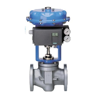
Siemens SIPART PS2 PA 6DR55 Series Operating Instructions Manual (292 pages)
Electropneumatic Positioner
Brand:
Siemens
| Category:
Valve Positioners
| Size: 16.67 MB
Table of Contents
5
Table of Contents
11
Introduction
11
Purpose of This Document
11
History
12
Further Information
13
2 General Safety Notes
13
General Information
13
Correct Usage
13
Laws and Directives
14
Measures
15
Qualified Personnel
15
Commissioning
17
Description
17
Function
17
Structure
17
Design Overview
20
Type Plate Structure
20
Technical Data
21
Operation with Natural Gas
21
Safety Notes for Operation with Natural Gas
21
Natural Gas As an Actuator Medium
23
Device Components
23
Overview of Device Components
25
Motherboard
25
Electrical Connections
26
Pneumatic Connections
26
Pneumatic Connection On the Standard Controller
27
Pneumatic Connection in the Flameproof Enclosure
27
Pneumatic Connection Versions
29
Purge Air Switching
29
Restrictors
30
Functional Principle
30
Control System
30
Microcontroller
31
Pneumatic Actuator
31
Control Algorithm
32
Profibus Pa
32
Overview
32
Transmission Technology
32
Bus Topology
33
Properties
33
Profile
34
Connection
35
Number of Connectable Devices
36
Assigning the Device Addresses
36
Simatic Pdm
37
4 Installation
37
Safety Notes for Installation
38
Installing the Linear Actuator
43
Installing the Part-Turn Actuator
48
Using the Positioner in a Humid Environment
50
Notes for Using Positioners That Are Exposed to Strong Accelerations or Vibrations
51
Setting the Friction Clutch
52
Switching the Transmission Ratio
53
External Position Displacement Sensor
55
5 Installing the Optional Modules
55
General Information about the Installation of Option Modules
55
Safety Notes for Installing the Option Modules
56
Installing Optional Modules in the Standard and Intrinsically Safe Version
58
Installing the Optional Modules in the "Flameproof Enclosure" Version
60
Installing the Module Cover
61
Iy Module
62
Alarm Unit
63
Slotted Initiator Alarm Unit
63
SIA Unit
64
Installing the Slotted Initiator Alarm Unit
65
Setting the Limits of the Slotted Initiator Alarm Unit
66
Mechanical Limit Switch Module
66
Installing the Mechanical Limit Switch Module
68
Setting the Limits of the Mechanical Limit Switch Module
68
EMC Filter Module
70
Accessories
71
Set of Signs for the Non-Intrinsically Safe Version
73
6 Connect
73
Connect Electrically
73
Note Regarding Electromagnetic Compatibility
74
Safety Notes for Electrical Connections
75
Interference Immunity
76
Safety Shutdown
76
Bus Cable
76
Preparing the Bus Cables
76
Installing the Bus Cable
78
Connections for "Non-Intrinsically Safe" Versions or Versions with "Flameproof Enclosures
78
Standard Controller
79
Current Output
80
Binary Inputs and Outputs
80
SIA Unit
81
Mechanical Limit Switch Module
85
Connection for the "Intrinsically Safe" Type of Protection
85
Standard Controller
86
Current Output
87
Binary Inputs and Outputs
88
SIA Unit
88
Mechanical Limit Switch Module
92
Connection for the "N" Type of Protection
92
Standard Controller
92
Current Output
93
Binary Inputs and Outputs
94
SIA Unit
95
Pneumatic Connection
97
Operation
97
Operating Elements
97
Digital Display
100
Firmware Version
100
Operating Modes
100
Overview of Operating Modes
101
Changing the Operating Mode
102
Overview of Configuration
102
Description of Operating Modes
104
Optimizing the Controller Data
107
8 Functional Safety
107
General Safety Notes
107
Safety-Instrumented System
109
Safety Integrity Level (SIL)
110
Device-Specific Safety Notes
110
Application Range for Functional Safety
110
Safety Function
111
Settings
112
Behavior in Case of Faults
113
Maintenance/Checking
113
Safety Characteristics
115
9 Commissioning
115
Overview
116
Sequence of Automatic Initialization
122
Commissioning the Linear Actuators
122
Preparing Linear Actuators for Commissioning
123
Automatic Initialization of Linear Actuators
125
Manual Initialization of Linear Actuators
128
Commissioning the Part-Turn Actuators
128
Preparing Part-Turn Actuators for Commissioning
129
Automatic Initialization of Part-Turn Actuators
130
Manual Initialization of Part-Turn Actuators
133
Copying the Initialization Data When Replacing a Positioner
135
10 Parameter Assignment/Addressing
135
Overview of the Parameters
135
Overview of Parameters 1 to 5
136
Overview of Parameters 6 to 53
139
Overview Parameters a to P
142
Description of Parameters
142
Description of Parameters 1 to 5
144
Description of Parameters 3 to 5
145
Description of Parameters 6 to 53
145
Description of Parameter 6
145
Description of Parameters 7 and 8
145
Description of Parameter 9
146
Description of Parameters 10 to 30
147
Description of Parameter 31
147
Description of Parameters 32 and 33
148
Description of Parameter 34
149
Description of Parameter 35
150
Description of Parameters 36 and 37
150
Description of Parameters 38 and 39
151
Description of Parameter 40
153
Description of Parameters 41 and 42
153
Description of Parameter 43
154
Description of Parameter 44
154
Description of Parameter 45
155
Description of Parameter 46
155
Description of Parameter 47
156
Description of Parameter 48
157
Description of Parameter 49
157
Description of Parameter 50
158
Description of Parameter 51
158
Description of Parameter 52
158
Description of Parameter 53
159
Description of Parameters a to P
159
Description of Parameter a
162
Description of Parameter B
163
Description of Parameter C
165
Description of Parameter D
166
Description of Parameter E
167
Description of Parameter F
168
Description of Parameter G
169
Description of Parameter H
170
Description of Parameter J
172
10.2.3.10 Description of Parameter L
173
10.2.3.11 Description of Parameter O
174
10.2.3.12 Description of Parameter P
177
11 Functions/Operations Using PROFIBUS PA
177
System Integration
177
Acyclic Data Transfer
177
Acyclic Data Transfer Using SIMATIC PDM
178
Device" Menu
178
Communication Path
178
Load Into Devices
178
Load Into PG/PC
179
Update Diagnostics Status
179
Set Address
179
Operation
181
Simulation
182
Partial Stroke Test (PST)
183
PST Trace Characteristic
183
11.2.2.10 Status Monitoring
184
11.2.2.11 Initialization Parameters
184
11.2.2.12 Initialization
185
11.2.2.13 Reset PDM Parameters
185
11.2.2.14 Reset the Field Device
186
11.2.2.15 Write Lock
187
View" Menu
187
Measured Value Display
187
Characteristic
188
Device Status
189
Maintenance Information
190
Trend Characteristic
190
Histograms
191
Adjusting the View of SIMATIC PDM
192
Cyclic Data Transfer
192
Configuration
195
Useful Data Through PROFIBUS
197
Possible Combinations of the Useful Data
201
Diagnostics
202
Adjustable Status (Condensed Status)
205
Diagnostics Messages in Case of Deactivated Condensed Status
206
Diagnostics Messages in Case of Activated Condensed Status
209
Definition of the Status
209
Sub-Status for Deactivated Condensed Status
210
Sub-Status for Activated Condensed Status
211
List of Diagnostics Events with Status and Diagnostics Message for Deactivated Condensed Status
213
List of Diagnostics Events with Status and Diagnostics Message for Activated Condensed Status
217
12 Alarm, Fault and System Messages
217
Representation of System Messages On the Digital Display
217
System Messages before Initialization
218
System Messages During Initialization
220
System Messages When Exiting the Configuration Mode
221
System Messages During Operation
223
Diagnostics
223
Display of Diagnostics Values
223
Overview of Diagnostics Values
225
Meaning of Diagnostics Values
231
Online Diagnostics
231
Overview of Online Diagnostics
231
XDIAG Parameter
232
Overview of Error Codes
233
Meaning of Error Codes
236
Fault Correction
236
Fault Identification
236
Remedial Measures Table 1
237
Remedial Measures Table 2
238
Remedial Measures Table 3
238
Remedial Measures Table 4
239
Remedial Measures Table 5
241
13 Service and Maintenance
241
Positioner in the Metal Enclosure and in the Flameproof Enclosure
242
Positioner in the Plastic Enclosure
243
14 Technical Data
243
General Technical Data
246
Technical Data of SIPART PS2 PA
249
Technical Data of Optional Modules
253
15 Dimension Drawings
257
16 Scope of Delivery/Spare Parts/Accessories
257
Overview
259
Standard Controller
260
Optional Modules
261
Spare Parts
263
Scope of Delivery of Small Part Sets
265
Accessories
267
Appendix
267
Bibliography/Catalogs/Standards
267
A.1 Bibliography/Catalogs/Standards
268
SIL Declaration of Conformity
269
Test Report
269
A.3 Test Report
273
Abbreviations
273
List of Abbreviations
273
B.1 List of Abbreviations
277
Glossary
287
Index
Advertisement
Share and save
Advertisement
Related Products
Siemens SIPART PS2 6DR51xx
Siemens SIPART PS2 6DR52 Series
Siemens SIPART PS2 6DR53 Series
Siemens SIPART PS2 6DR5xx0 series
Siemens SIPART PS2 6DR5xx1 series
Siemens SIPART PS2 6DR5xx3 series
Siemens SIPART PS2 6DR5011 Series
Siemens SIPART PS2 6DR5111 Series
Siemens SIPART PS2 6DR5210 Series
Siemens SIPART PS2 6DR59 Series
Siemens Categories
Controller
Control Unit
Switch
Measuring Instruments
Industrial Equipment
More Siemens Manuals
Login
Sign In
OR
Sign in with Facebook
Sign in with Google
Upload manual
Upload from disk
Upload from URL