Sign In
Upload
Manuals
Brands
Secutron Manuals
Control Unit
MODUL-R MR-2100
Secutron MODUL-R MR-2100 Manuals
Manuals and User Guides for Secutron MODUL-R MR-2100. We have
5
Secutron MODUL-R MR-2100 manuals available for free PDF download: Installation Manual, Programming Manual, Operator's Manual, Operating Instructions
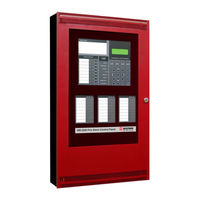
Secutron MODUL-R MR-2100 Installation Manual (1077 pages)
Fire alarm control unit
Brand:
Secutron
| Category:
Control Unit
| Size: 19.06 MB
Table of Contents
Table of Contents
5
Technical Information
9
General Installation Requirements
10
System Components
11
Table 1: AC Input
16
Table 2: Battery Power (Use Sealed Lead Acid Batteries Only!)
16
Technical Specifications
16
Table 3: Addressable Input (Signaling Line Circuit)
17
Table 4: Notification Appliance Circuit Output Circuits
17
Table 5: Function Relay Output Circuits
17
Table 6: Power Outputs
17
Table 7: Communications Ports
18
Table 8: Environmental Specifications
18
Installation
19
Figure 1: Knockouts and Mounting Holes
21
Figure 2: Power Limited Wiring Diagram
22
Internal Assembly
22
Figure 3: Power Limited Wiring, City Module
23
Figure 4: AC Power Wiring Diagram
24
Wiring
24
Figure 5. External Battery Cabinet Wiring
25
Figure 6: Class B Wiring
26
Figure 7: Class a Circuit
26
Figure 8: Class B NAC Wiring
27
Figure 9: Class a NAC Wiring
27
Figure 10: Function Relay Wiring
27
Maximum Wiring Length for Addressable Circuits
28
Maximum Wiring Length for Bell Circuits
29
Table 9: Secutron Compatible Addressable Devices
30
Table 10: System Sensor Compatible Addressable Devices
31
4.0 Appendix A Compatible Addressable Devices
32
5.0 Appendix B: Battery Calculations & Compatible Batteries
32
Battery Calculation Worksheet
32
Battery Selection Calculations
34
Appendix C: Compatible Notification Appliances
35
Gentex
37
System Sensor
38
Table of Contents
43
General Information
47
Annunciators Window
67
Outputs Dialog
68
Options Dialog
70
Front Panel
138
Power Supply
139
Mounting and Assembling Unit
140
Parts List
150
Appendix B: Ul Listed Compatible Devices
153
5.0 Appendix A: Stand-By Battery Calculation
153
Appendix C: Interconnection to Other Equipment
168
Limited Warranty
173
Table of Contents
259
Input Circuits Modules
264
Terminal Board
265
Annunciator Strip
266
Optional Integrated Printer
267
Appendix B: Ulc Listed Compatible Smoke Detectors
289
5.0 Appendix A: Stand-By Battery Calculation
289
Appendix C: Ul Listed Compatible Devices
290
Smoke Detectors a
290
Smoke Detectors B
293
Appendix D: Interconnection to Other Equipment
312
Diagnostic Leds
402
Table of Contents
413
The Mr-2602 Fire Alarm Control Unit
415
2 Preparing to Install the Mr-2602 Fire Panel
417
Mr-2602 Overview
419
3 Installing the Mr-2602 Fire Panel
423
6 Programming the Mr-2602 System
437
9 0 Appendix: Table of Compatible Smoke Detectors
451
9.1 Smoke Detector Bases
453
9.2 Compatible 4-Wire Smoke Detectors
453
9.3 Compatible Horns/Strobes
454
FCC Compliance Statement
456
Warranty and Warning Information
457
Warning Please Read Carefully
457
Limited Warranty
460
Table of Contents
468
9.0 Appendix: Table of Compatible Smoke Detectors
507
9.1 Smoke Detector Bases
509
9.2 Compatible 4-Wire Smoke Detectors
509
9.3 Compatible Horns/Strobes
510
FCC Compliance Statement
512
Warranty and Warning Information
513
Warning Please Read Carefully
513
Limited Warranty
516
Specifications
519
Table of Contents
549
General Features of the Mrdl
553
2 Installing and Wiring the Mrdl
555
Unpacking the Mrdl
555
Mounting & Wiring the Mrdl
555
3 Mrdl Operation
556
Led Indicators
556
Communication with the Fire Alarm Control Panel
556
Phone Line Communication
556
4 Programming the Mrdl
557
Accessing the Dialer Settings
557
Dialer Settings
558
5 Appendix A: Table of Reporting Codes
563
Contact ID
563
Sia Format – Level 2 (Hardcoded)
563
6 Appendix B: Table of Compatible Receivers
566
Warranty and Warning Information
567
Table of Contents
588
Figure 2: Box Dimensions, Semi-Flush Mounting and Trim Ring
601
Mr-2300-Nc4\Nc2 Output Class-A Converter Adder Module
605
Figure 6: Mr-2300-Nc4\Nc2 Output Class-A Converter Adder Module
605
Figure 7: Mr-2312-R12 Twelve Relay Adder Module
605
Figure 8: Mr-2312-R12/2306-R6 Relay Programming
606
Figure 9: Mr-2306-R6 Six Relay Adder Module
606
Figure 12: Initiating Circuit– Class a or Style D Wiring
609
Figure 13: Indicating Circuit – Class B or Style y Wiring
609
Figure 14: Indicating Circuit –Class a or Style Z Wiring
610
Figure 15: Four-Wire Smoke Detector Wiring
610
Troubleshooting
617
Indicators, Controls and Operations
618
Common Indicators
619
Alarm Circuit Indicators
621
Supervisory Circuit Indicators
621
Monitor Circuit Indicators
621
Trouble-Only Circuit Indicators
622
Signal Circuit Indicators
622
Common Controls
622
Circuit (Zone) Disconnect Buttons
623
Common Relays
624
Circuit Types
624
Evacuation Codes
626
Single Stage Operation
627
Two-Stage Operation
627
Supported Protocols/Devices
629
Synchronous Strobes
629
System Sensor's I3 Devices
629
Configuration and CFG-300 LCD Service Tool
631
Entering the Passcode
632
Command Menu
632
CONFIG (Command-Menu)
633
Config Info
642
Set Time (Command-Menu)
643
Change Password (Command-Menu)
644
View Event Log (Command-Menu)
644
Clear Event Log (Command-Menu)
645
Walk Test (Command-Menu)
646
I3 Loop Test (Command-Menu)
647
Dialer Config (Command-Menu)
648
Test Dialer (Command-Menu)
654
Exit (Command-Menu)
656
CFG-300 LCD Service Tool Operation
656
Appendix A: Compatible Receivers
660
Appendix B: Reporting
661
Ademco Contact-ID
661
Security Industries Association SIA-DCS
662
Appendix C: Specifications
663
Appendix D: Power Supply and Battery Calculations (Selection Guide)
664
Warranty
665
Table of Contents
673
Industry Canada and FCC Notice
677
Introduction
678
Overall Features
678
Conventions
679
Circuits
679
Zone
679
Events
679
Wiring Styles
679
System Components, Sub-Assemblies & Accessories
680
Main Fire Control Panel
680
Relay Module: 12 Relays
681
Relay Modules: Six Relays
681
Polarity Reversal/City Tie
681
Remote Annunciator
682
Smart Relay Module
682
Input Class a Converter: Six Circuits
682
Output Class a Converter: Four Circuits
683
Output Class a Converter: Two Circuits
683
Active End-Of-Line
683
MR-2312-AT Remote Annunciator
683
Additional Fire Alarm System Accessories
683
Mechanical Installation
684
Installing the Enclosure
684
Figure 2: Mr-2312-Ddr Box Dimensions, Semi-Flush Mounting with Trim Ring
685
Figure 2A: Mr-2306-Ddr6Dr Box Dimensions, Mounting and Trim Ring
686
Installing the Adder Modules
687
Figure 3: Installation of Adder Modules for Mr-2312 Lcd Panels
687
Figure 4: Installation of Adder Modules for Mr-2306 Lcd Panels
688
DIP Switch and Jumper Selections for Main Board and Adder Modules
689
Main Fire Alarm Board
689
MR-2300-A Input Class-A Converter Adder Module
691
MR-2300-NC4/2 Output Class-A Converter Adder Module
692
Relay Adder Modules (Models MR-2312-R12 and MR-2306-R6)
692
Figure 10: Mr-2312/06-R12/6 Relay Programming
693
MR-2306-R6 Six Relay Adder Module
693
Polarity Reversal and City Tie Module (Model MR-2300-PR)
694
Field Wiring
695
Main Fire Alarm Board Field Wiring
695
Figure 13: Initiating Circuit – Class B or Style B Wiring
695
Figure 14: Initiating Circuit– Class a or Style D Wiring
696
Figure 15: Indicating Circuit – Class B or Style y Wiring
696
Figure 16: Indicating Circuit – Class a or Style Z Wiring
697
Figure 17: Four-Wire Smoke Detector Wiring
697
Figure 18: Dialer Wiring
698
Relay Adder Module Wiring
699
Figure 20: Relay Per Zone (Mr-2306-R6) Terminal Connection
699
Polarity Reversal and City Tie Module (MR-2300-PR) Wiring
700
Power Supply Connection
700
Figure 21: Polarity Reversal and City Tie Module Terminal Connection
700
Wiring Tables and Information
701
Figure 22: Power Supply Connection
701
Four-Wire Smoke Power (Regulated)
702
Supervised Auxiliary Power (Regulated)
702
Auxiliary Power (Unregulated)
702
Before Turning the Power "ON
703
Power-Up Procedure
703
Troubleshooting
703
System Checkout
703
Figure 23: Lcd Display and Control Buttons
704
Common Indicators
705
Common Controls
705
Common Relays
706
Circuit Types
707
Evacuation Codes
708
Figure 24: Evacuation Codes
708
Fire Alarm Operation
709
Indicators, Controls and Operations
704
Supported Protocols/Devices
710
Synchronous Strobes
710
System Sensor's I3 Devices
710
Configuration
712
Entering the Passcode
712
Figure 25: Mr-2300 Configuration
712
Command Menu
713
CONFIG (Command-Menu)
714
Command Menu/Mr-2300 Config-->Features
714
Config Info (Command-Menu)
722
Set Time (Command-Menu)
723
Set Password (Command-Menu)
724
View Event Log (Command-Menu)
724
Clear Event Log (Command-Menu)
725
Walk Test (Command-Menu)
726
I3 Loop Test (Command-Menu)
727
Dialer Config (Command-Menu)
728
Test Dialer (Command-Menu)
733
Bypass Det Ckt (Command-Menu)
735
Bypass NAC Ckt (Command-Menu)
735
Aux. Disconnect (Command-Menu)
735
Exit (Command-Menu)
736
Appendix A: Compatible Receivers
741
Appendix B: Reporting
742
Ademco Contact-ID
742
Security Industries Association SIA-DCS
743
Appendix C: Specifications
744
Appendix D: Power Supply and Battery Calculations (Selection Guide)
746
Warranty & Warning Information
748
Warning Please Read Carefully
748
Limited Warranty
750
Warranty Procedure
750
Disclaimer of Warranties
750
Out of Warranty Repairs
751
Table of Contents
754
Industry Canada and FCC Notice
758
Introduction
759
Panel Type
759
Overall Features
759
Conventions
760
Circuits
760
Zone
760
Display Points
760
Wiring Styles
760
System Components
761
Main Pre-Action/Deluge and Agent Release Control Panel
761
Relay Modules: Six Relays
761
Polarity Reversal/City Tie
761
Smart Relay Module
762
Input Class a Converter: Six Circuits
762
Output Class a Converter: Two Circuits
762
MR-2312-ATW Remote Annunciator
762
Active End-Of-Line
763
Additional System Accessories
763
Mechanical Installation
764
Installing the Enclosure
764
Installing the Adder Modules
766
Cable and Jumper Connections for Main Board and Adder Modules
767
Main Pre-Action/Deluge and Agent Release Control Board
767
MR-2300-A Input Class-A Converter Adder Module
768
MR-2300-NC2 Output Class-A Converter Adder Module
769
Polarity Reversal and City Tie Module (Model MR-2300-PR)
770
Field Wiring
771
Main Board Field Wiring
771
Abort and Manual Release Switch Wiring
773
Indicating Circuit Wiring
775
Dialer Wiring
776
Relay Adder Module Wiring
777
Polarity Reversal and City Tie Module (MR-2300-PR) Wiring
778
Power Supply Connection
779
Wiring Tables and Information
780
Four-Wire Smoke Power (Regulated)
780
Supervised Auxiliary Power (Regulated)
780
Auxiliary Power (Unregulated)
781
Before Turning the Power "ON
782
Power-Up Procedure
782
Troubleshooting
782
System Checkout
782
Indicators, Controls and Operations
783
Common LED Indicators
783
Menu Buttons
785
Switches and Common Indicators
785
Common Controls
786
Circuit (Zone) Disconnect Buttons
786
Common Relays
787
Circuit Types
787
Evacuation Codes
788
Configuration
789
Using the CFG-300 Tool
789
Entering the Passcode
790
Command Menu
791
Panel Config (Command-Menu)
792
Set Time (Command-Menu)
798
Set Password (Command-Menu)
799
View Event Log (Command-Menu)
800
Clear Event Log (Command-Menu)
800
Dialer Config (Command-Menu)
801
Test Dialer (Command-Menu)
806
Exit (Command-Menu)
808
Operating the Panel
809
Panel Operation During Various Hazard States
809
General Panel Operation
810
Pre-Programmed Modes
811
Mode 1: Agent Release, Single Hazard, Cross-Zoned, Combined Release
811
Mode 2: Agent Release, Single Hazard, Not Cross-Zoned, Combined Release
813
Mode 3: Agent Release, Dual Hazard, Cross-Zoned, Split Release
815
Mode 4: Agent Release, Dual Hazard, Not Cross-Zoned, Split Release
817
Mode 5: Pre-Action/Deluge, Single Hazard, Cross-Zoned, Combined Release
819
Mode 6: Pre-Action/Deluge, Single Hazard, Not Cross-Zoned, Combined Release
820
Mode 7: Pre-Action/Deluge, Dual Hazard, Cross-Zoned, Split Release
821
Mode 8: Pre-Action/Deluge, Dual Hazard, Not Cross-Zoned, Split Release
823
Mode 9: Agent Release, Single Hazard, Cross-Zoned, NYC Abort
825
Mode 10: Agent Release, Single Hazard, Not Cross-Zoned, Combined Release
827
Mode 11: Agent Release, Single Hazard, Cross-Zoned, Combined Release
829
Appendix A: Compatible Receivers
831
Appendix B: MR-2320 Compatible Devices
832
Appendix C: Reporting
834
Ademco Contact-ID
834
Security Industries Association SIA-DCS
835
Appendix D: Specifications
836
Appendix E: Power Supply and Battery Calculations (Selection Guide)
837
Warranty
840
Table of Contents
844
List of Tables & Figures
846
Industry Canada and FCC Notice
848
Introduction
849
Panel Type
849
Overall Features
849
Conventions
850
Circuits
850
Zone
850
Display Points
850
Wiring Styles
850
System Components
851
Main Pre-Action/Deluge and Agent Release Control Panel
851
Relay Modules: Six Relays
851
Polarity Reversal/City Tie
851
Smart Relay Module
852
Input Class a Converter: Six Circuits
852
Output Class a Converter: Two Circuits
852
MR-2312-ATW Remote Annunciator
852
Active End-Of-Line
853
Additional System Accessories
853
Mechanical Installation
854
Installing the Enclosure
854
Installing the Adder Modules
856
Cable and Jumper Connections for Main Board and Adder Modules
857
Main Pre-Action/Deluge and Agent Release Control Board
857
MR-2300-A Input Class-A Converter Adder Module
858
MR-2300-NC2 Output Class-A Converter Adder Module
859
Polarity Reversal and City Tie Module (Model MR-2300-PR)
860
Field Wiring
861
Main Board Field Wiring
861
Abort and Manual Release Switch Wiring
863
Indicating Circuit Wiring
865
Dialer Wiring
866
Relay Adder Module Wiring
867
Polarity Reversal and City Tie Module (MR-2300-PR) Wiring
868
Power Supply Connection
869
Wiring Tables and Information
870
Four-Wire Smoke Power (Regulated)
870
Supervised Auxiliary Power (Regulated)
870
Auxiliary Power (Unregulated)
871
Before Turning the Power "ON
872
Power-Up Procedure
872
Troubleshooting
872
System Checkout
872
Indicators, Controls and Operations
873
Common LED Indicators
873
Menu Buttons
875
Switches and Common Indicators
875
Common Controls
876
Circuit (Zone) Disconnect Buttons
876
Common Relays
877
Circuit Types
877
Evacuation Codes
878
Configuration
879
Using the CFG-300 Tool
879
Entering the Passcode
880
Command Menu
881
Panel Config (Command-Menu)
882
Set Time (Command-Menu)
888
Set Password (Command-Menu)
889
View Event Log (Command-Menu)
890
Clear Event Log (Command-Menu)
890
Dialer Config (Command-Menu)
891
Test Dialer (Command-Menu)
896
Exit (Command-Menu)
898
Operating the Panel
899
Panel Operation During Various Hazard States
899
General Panel Operation
900
Pre-Programmed Modes
901
Mode 1: Agent Release, Single Hazard, Cross-Zoned, Combined Release
901
Mode 2: Agent Release, Single Hazard, Not Cross-Zoned, Combined Release
903
Mode 3: Agent Release, Dual Hazard, Cross-Zoned, Split Release
905
Mode 4: Agent Release, Dual Hazard, Not Cross-Zoned, Split Release
907
Mode 5: Pre-Action/Deluge, Single Hazard, Cross-Zoned, Combined Release
909
Mode 6: Pre-Action/Deluge, Single Hazard, Not Cross-Zoned, Combined Release
910
Mode 7: Pre-Action/Deluge, Dual Hazard, Cross-Zoned, Split Release
911
Mode 8: Pre-Action/Deluge, Dual Hazard, Not Cross-Zoned, Split Release
913
Mode 9: Agent Release, Single Hazard, Cross-Zoned, NYC Abort
915
Mode 10: Agent Release, Single Hazard, Not Cross-Zoned, Combined Release
917
Mode 11: Agent Release, Single Hazard, Cross-Zoned, Combined Release
919
Appendix A: Compatible Receivers
921
Appendix B: MR-2320 Compatible Devices
922
Appendix C: Reporting
924
Ademco Contact-ID
924
Security Industries Association SIA-DCS
925
Appendix D: Specifications
926
Appendix E: Power Supply and Battery Calculations (Selection Guide)
927
Table of Contents
936
Introduction
937
About this Manual
937
Technical Supporttechnical Support
937
Main Display
938
The Buzzer and LED Indicators
939
Common LED Indicators
939
Alarm Circuit Indicators
941
Supervisory Circuit Indicators
941
Monitor Circuit Indicators
941
Trouble-Only Circuit Indicators
942
Signal Circuit Indicators
942
Main Display Buttons
943
Circuit (Zone) Disconnect Buttons
944
Glossary
945
Table of Contents
949
Main Display
950
Introduction
950
About this Manual
950
Technical Support
950
The Buzzer and LED Indicators
951
Buzzer
951
AC on LED
951
Alarm LED
951
Supervisory LED
951
Trouble LED
951
CPU Fail LED
951
Main Display Buttons
952
System Reset Button
952
Signal Silence Button
952
Fire Drill Button
952
Lamp Test Button
952
Buzzer Silence Button
952
The up and down Arrow Buttons
952
The Info Button
952
The Enter, Menu, and Cancel Buttons
952
Disconnecting/Reconnecting a Circuit (Zone)
953
Understanding On-Screen Messages
954
Common Messages
955
Glossary
959
Table of Contents
964
Industry Canada and FCC Notice
968
Introduction
969
Overall Features
969
Conventions
970
Circuits
970
Zone
970
Display Points
970
Wiring Styles
970
System Components
971
Main Fire Control Panel
971
Relay Modules: Six Relays
971
Polarity Reversal/City Tie
971
Remote Annunciator
972
Smart Relay Module
972
Input Class a Converter: Six Circuits
973
Output Class a Converter: Two Circuits
973
Active End-Of-Line
973
MR-2312-AT Remote Annunciator
973
Additional Fire Alarm System Accessories
973
Mechanical Installation
974
Installing the Enclosure
974
Installing the Adder Modules
975
Cable and Jumper Connections for Main Board and Adder Modules
976
Main Fire Alarm Board
976
Figure 3: Main Fire Alarm Board Cable Connector and Jumper Settings
976
MR-2300-A Input Class-A Converter Adder Module
977
MR-2300-NC2 Output Class-A Converter Adder Module
978
MR-2306-R6 Six Relay Adder Module
978
Figure 7: Mr-2306-R6 Relay Programming
979
Polarity Reversal and City Tie Module (Model MR-2300-PR)
979
Field Wiring
980
Main Fire Alarm Board Field Wiring
980
Figure 9: Initiating Circuit – Class B or Style B Wiring
980
Figure 10: Initiating Circuit– Class a or Style D Wiring
981
Figure 11: Indicating Circuit – Class B or Style y Wiring
981
Figure 12: Indicating Circuit –Class a or Style Z Wiring
982
Figure 13: Four-Wire Smoke Detector Wiring
982
Relay Adder Module Wiring
983
Figure 14: Dialer Wiring
983
Figure 15: Relay Per Zone (Mr-2306-R6) Terminal Connection
983
Polarity Reversal and City Tie Module (MR-2300-PR) Wiring
984
Figure 16: Polarity Reversal and City Tie Module Terminal Connection
984
Power Supply Connection
985
Figure 17: Power Supply Connection
985
Wiring Tables and Information
986
Four-Wire Smoke Power (Regulated)
986
Supervised Auxiliary Power (Regulated)
986
Auxiliary Power (Unfiltered)
986
Before Turning the Power "ON
987
Power-Up Procedure
987
Troubleshooting
987
System Checkout
987
Figure 18: Led Indicators and Control Buttons
988
Common Indicators
989
Alarm Circuit Indicators
990
Supervisory Circuit Indicators
990
Monitor Circuit Indicators
991
Trouble-Only Circuit Indicators
991
Signal Circuit Indicators
991
Common Controls
992
Circuit (Zone) Disconnect Buttons
993
Common Relays
993
Circuit Types
994
Evacuation Codes
995
Single Stage Operation
996
Figure 19: Evacuation and Alert Codes
996
Indicators, Controls and Operations
988
Supported Protocols/Devices
997
Synchronous Strobes
997
System Sensor's I3 Devices
997
Configuration and CFG-300 LCD Service Tool
999
Figure 20: Mr-2306 Configuration
999
Entering the Passcode
1000
Command Menu
1000
PANEL CONFIG (Command-Menu)
1001
Aux Dis, Alm&Sup
1002
Config Info
1010
Set Time (Command-Menu)
1011
Set Password (Command-Menu)
1012
View Event Log (Command-Menu)
1012
Clear Event Log (Command-Menu)
1013
Walk Test (Command-Menu)
1014
I3 Loop Test (Command-Menu)
1015
Dialer Config (Command-Menu)
1016
Test Dialer (Command-Menu)
1021
Exit (Command-Menu)
1023
CFG-300 LCD Service Tool Operation
1023
Appendix A: Compatible Receivers
1027
Appendix B: Reporting
1028
Ademco Contact-ID
1028
Security Industries Association SIA-DCS
1029
Appendix C: Specifications
1030
Appendix D: Power Supply and Battery Calculations (Selection Guide)
1031
Warranty & Warning Information
1032
Warning Please Read Carefully
1032
Limited Warranty
1034
Warranty Procedure
1034
Disclaimer of Warranties
1034
Out of Warranty Repairs
1035
Introduction
1044
Mechanical Installation
1044
Functional Setup
1045
Jumpers
1045
DIP Switches
1046
Configuration of the Relays
1047
Wiring
1048
Specifications & Features
1049
Introduction
1060
Mechanical Installation
1061
Functional Setup
1062
Jumpers
1062
Potentiometer
1062
DIP Switches
1063
Wiring
1064
Specifications & Features
1066
Enclosure
1066
Electrical Specifications
1066
Current Drain for Battery Calculations
1066
Operating Instructions
1067
Advertisement
Secutron MODUL-R MR-2100 Programming Manual (76 pages)
Fire Alarm Control Panel
Brand:
Secutron
| Category:
Control Panel
| Size: 2.62 MB
Table of Contents
Table of Contents
3
1 Operation and Programming Concepts
7
Introduction
7
General Information
8
Networks
8
Figure 1 Typical Network Layout
8
Figure 2 Single Network Break
10
Addressable Devices
11
Figure 3 Panel Removed from Network
11
Resetting 4-Wire Detectors
14
Figure 4 Four Wire Device Wiring (Typical)
15
2 Editing MHI Databases
16
Introduction
16
General Comments
16
System Window
17
Figure 5 Modul-R System Window
17
Switches Window
21
Figure 6 Switches Window
22
Groups Window
23
Figure 7 Groups Window
23
Panel Window
25
Figure 8 Panel Window
25
Outputs Dialog
29
Figure 9 Panel Outputs
29
Options Dialog
30
Figure 10 Options Dialog
30
Figure 11 Default Key Assignments
33
Figure 13 Dialer Settings
36
Figure 14 Dialer Configuration 1
37
Figure 15 Dialer Configuration 2
39
Figure 16 Call Directions
40
Figure 17 Zone Data
40
Circuits and Devices Windows
41
Figure 18 Dialer Maintenance and Common Reporting Codes
41
Figure 19 Circuits Window
42
Figure 20 Devices Window
42
Figure 21 Copy Window
45
2.10 Internal Circuits Window
46
Figure 22 Internal Circuits Window
47
2.11 Relate Window
48
Figure 23 Relate Window
48
2.12 Pushbuttons
49
3 LCD Programming
50
Introduction
50
General Comments
50
Figure 24 Program Menu
50
Menus
51
Figure 25 Selector Screen
51
4 Appendix A: Condition Codes and Zone Numbers
58
Introduction
58
List of Codes and Zone Numbers
58
5 Appendix B: Stand-By Battery Calculation
64
6 Appendix C: Service Terminal
65
General
65
Control Unit
65
7 Appendix D: Table of Reporting Codes
73
Secutron MODUL-R MR-2100 Installation Manual (38 pages)
Fire Alarm Control Unit
Brand:
Secutron
| Category:
Control Unit
| Size: 2.33 MB
Table of Contents
Table of Contents
3
1 Technical Information
7
Introduction
7
Features
7
Codes & Standards
7
Applications & Services
8
General Installation Requirements
8
System Verification
8
System Components
9
2 Technical Specifications
14
Electrical Specifications
14
3 Installation
17
Unpacking the MR-2100 or MR-2200
17
Mounting and Assembling the MR-2100/MR-2200
17
Internal Assembly
20
Wiring
22
Maximum Wiring Length for Addressable Circuits
26
Maximum Wiring Length for Bell Circuits
26
4 Appendix A: Compatible Addressable Devices
27
5 Appendix B: Battery Calculations & Compatible Batteries
28
Battery Calculation Worksheet
28
Battery Selection Calculations
30
6 Appendix C: Compatible Synchronized Notification Appliances
31
7 Warranty & Warning Information
32
Limited Warranty
34
Advertisement
Secutron MODUL-R MR-2100 Operator's Manual (20 pages)
Fire Alarm Control Unit
Brand:
Secutron
| Category:
Control Unit
| Size: 0.53 MB
Table of Contents
Table of Contents
4
1 Unit Operation
6
Power up Sequence
6
Types of Inputs
6
Status Display
6
Zone Leds
7
Buzzer
7
Operator Keys
8
Alarm List
11
LCD and Keypad
12
2 Supplementary Information
15
Condition Codes and Zone Numbers
15
Miscellaneous Troubles
17
secutron MODUL-R MR-2100 Operating Instructions (1 page)
FIRE ALARM CONTROL UNIT
Brand:
secutron
| Category:
Control Unit
| Size: 0.1 MB
Advertisement
Related Products
Secutron MODUL-R MR-2200
Secutron MR-2300 series
Secutron MR-2900
Secutron MR-2312-AT
Secutron MR-2605
Secutron MR-2306-DDR
Secutron MR-2308-LR
Secutron MR-2300-LCD
Secutron MR-2306-DR
Secutron MR-2300-LCDR
Secutron Categories
Control Panel
Smoke Alarm
Fire Alarms
Control Unit
Security Sensors
More Secutron Manuals
Login
Sign In
OR
Sign in with Facebook
Sign in with Google
Upload manual
Upload from disk
Upload from URL